Systems and Methods for Securing a Storage Tank of a Water Heater on a Support Pad
US20260168699A1
2026-06-18
19/385,507
2025-11-11
Smart Summary: A fluid heating system has a housing that holds a storage tank for heating water. The storage tank is placed inside the housing to keep the water safe. A support pad is used to hold everything in place, featuring an outer lip that supports the housing. Additionally, the support pad has trenches that securely hold the bottom of the storage tank. This design helps keep the water heater stable and secure. 🚀 TL;DR
Abstract:
A fluid heating system including a housing, a storage tank, and a support pad is disclosed. The storage tank is disposed in the housing and stores the fluid to be heated. The support pad includes a body including an outer lip and one or more trenches formed in the body. The outer lip receives a bottom periphery of the housing, and the trenches receive a bottom periphery of the storage tank.
Inventors:
- William Tomlin McLemore 2 🇺🇸 Montgomery, AL, United States
- Jason Addison Steinbaum 3 🇺🇸 Auburn, AL, United States
- Matthew Connor Bishop 1 🇺🇸 Fairhope, AL, United States
- Robert A. Johnson 1 🇺🇸 Pike Road, AL, United States
- Thomas L. Porterfield, JR. 1 🇺🇸 Montgomery, AL, United States
Applicant:
Interested in similar patents?
Get notified when new applications in this technology area are published.
Classification:
F24H9/06 » CPC main
Details Arrangement of mountings or supports for heaters, e.g. boilers, other than space heating radiators
Description
CROSS-REFERENCE TO RELATED APPLICATIONS
The present application claims priority to and the benefit of U.S. provisional application No. 63/735,663, filed Dec. 18, 2024, which is hereby incorporated by reference herein in its entirety.
FIELD
The present disclosure relates to systems and methods for securing a storage tank and a housing of a water heater on a support pad.
BACKGROUND
Water heaters are generally used to provide a supply of heated water in a variety of applications, including residential, commercial, and industrial applications. A tank based water heater typically includes a storage tank that stores water that is heated by a heating source. The storage tank may be enclosed within a housing or a jacket that protects the storage tank from ambient environment. In many instances, the space between the storage tank and the housing is thermally insulated by using an insulating material (e.g., foam), which prevents heat from escaping the storage tank.
BRIEF DESCRIPTION OF THE DRAWINGS
The detailed description is set forth with reference to the accompanying drawings. The use of the same reference numerals may indicate similar or identical items. Various embodiments may utilize elements and/or components other than those illustrated in the drawings, and some elements and/or components may not be present in various embodiments. Elements and/or components in the figures are not necessarily drawn to scale. Throughout this disclosure, depending on the context, singular and plural terminology may be used interchangeably.
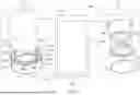
FIG. 1 depicts a block diagram of an example water heating system and top and bottom isometric views of a first exemplary support pad in accordance with one or more embodiments of the present disclosure.
FIG. 2 depicts top and cross-sectional views of the support pad of FIG. 1 in accordance with one or more embodiments of the present disclosure.
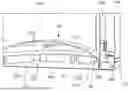
FIG. 3 depicts a cross-sectional view of an exemplary connection of the support pad of FIG. 1 with a storage tank and a housing in accordance with one or more embodiments of the present disclosure.
FIG. 4 depicts a bottom isometric view of an exemplary connection of the support pad of FIG. 1 with a storage tank and a housing in accordance with one or more embodiments of the present disclosure.
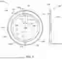
FIG. 5 depicts top and cross-sectional views of a second exemplary support pad in accordance with one or more embodiments of the present disclosure.
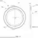
FIG. 6 depicts top and cross-sectional views of a third exemplary support pad in accordance with one or more embodiments of the present disclosure.
FIG. 7 depicts top and cross-sectional views of a fourth exemplary support pad in accordance with one or more embodiments of the present disclosure.
FIG. 8 depicts isometric views of a fifth exemplary support pad in accordance with one or more embodiments of the present disclosure.
FIG. 9 depicts a flow diagram of an exemplary method to connect one or more water heater components to a support pad in accordance with one or more embodiments of the present disclosure.
DETAILED DESCRIPTION
The present disclosure is directed to a fluid or water heating system (“system”) that may include a plurality of components including, but not limited to, a housing, a storage tank, a support pad, a bottom pan, and/or the like. The housing may enclose one or more system components and protect them from the ambient environment. For example, the housing may enclose the storage tank. The storage tank may store the fluid (e.g., water) to be heated by the system. In an exemplary aspect, the storage tank and the housing may have similar shapes and structures. For example, both the storage tank and the housing may be cylindrical. Further, a bottom wall of the storage tank may have a concave shape, such that the bottom wall may be curved “upwards” towards a top portion of the storage tank. Due to the concave-shaped curved structure of the tank bottom wall, a vacant area or a “negative space” may exist between the bottom wall and the ground (or any other surface, e.g., the bottom pan) when the storage tank is placed on the ground (or any other surface).
The bottom pan may cover the system from the bottom side. Stated another way, the system's bottom side (e.g., the bottom sides of the storage tank and the housing) may be covered by the bottom pan.
The support pad may receive the bottom peripheries of the housing and the storage tank and robustly secure or connect the storage tank and the housing within the system to ensure that the storage tank and the housing do not move relative to each other (e.g., during system transportation, operation, etc.).
In some aspects, to assemble the system, the bottom periphery of the storage tank may first be placed or connected to the support pad. The bottom periphery of the housing may then be placed or connected to the support pad. Responsive to connecting the storage tank and the housing to the support pad, the system's bottom side may be covered with the bottom pan, which may cover the negative space that exists at the bottom portion of the storage tank.
In some aspects, a diameter of the housing may be greater than a diameter of the storage tank. Therefore, when the storage tank and the housing are placed or connected to the support pad, a predefined vacant space or area may exist between the storage tank sidewalls and the housing sidewalls. In an exemplary aspect, to ensure that the storage tank does not lose heat from this vacant space, an insulating material (e.g., foam) may be injected in the vacant space from the system's top and/or side portions. The foam may ensure that the storage tank is effectively insulated within the housing and does not lose heat, thereby ensuring that the system's efficiency is enhanced/maintained.
The structure of the support pad, as disclosed in the present disclosure, ensures that the storage tank is “centered” in the housing when the system is assembled so that the vacant space is evenly present around the storage tank sidewalls. It may be appreciated that if the vacant space is not evenly present around the storage tank sidewalls (i.e., the storage tank is offset right or left relative to a housing's central longitudinal axis), one side of the storage tank may receive more insulating material than the other side, which may affect the system's operation and/or efficiency. The structure of the support pad, as disclosed in the present disclosure, ensures that storage tank is securely and robustly “centered” in the housing when the system is assembled so that the insulating material may be evenly distributed around the storage tank sidewalls.
Furthermore, in some embodiments, the structure of the support pad ensures that the insulating material enters the negative space that exists at the bottom portion of the storage tank so that the storage tank may be effectively insulated from the tank's bottom side (in addition to being insulated from the storage tank's side portion, as described above).
In certain embodiments, the support pad may be shaped as a circular ring including an outer edge and one or more inner edges. The outer edge and the inner edge(s) may be concentric edges. The outer edge may include an outer lip that may receive and secure the bottom periphery of the housing when the housing is placed on the support pad.
Further, the support pad may include one or more trenches or “U-shaped” cavities that may be concentric with the outer edge and the inner edge(s) and may be formed between the outer edge and the inner edge(s). The trenches may receive and secure the bottom periphery of the storage tank when the storage tank is placed on the support pad.
The support pad may further include one or more cut-outs that may be formed in the support pad body. Each cut-out may be formed between adjacent inner edges. The cut-outs may enable the insulating material to flow or seep into the negative space that exists at the bottom portion of the storage tank when the insulating material is injected between the storage tank and the housing.
In some aspects, the support pad may include three, six, or nine (or more) cut-outs. In alternative aspects, the support pad may not include any cut-out. In further aspects, the area or space enclosed within the inner edge(s) of the support pad and a support pad center point may be vacant or may not include any material. Since the area or space enclosed within the inner edge(s) does not include any material, the support pad as disclosed in the present disclosure utilizes less material (and hence resources, such as cost) than conventional support pads.
In alternative aspects, the area or space enclosed within the inner edge(s) of the support pad may include one or more reinforcement rods that may connect the inner edge(s) with the support pad center point. The reinforcement rods may provide structural integrity to the support pad, e.g., when the support pad receives a heavy storage tank and/or housing. In some aspects, the space between adjacent reinforcement rods may be vacant or may not include any material, thereby facilitating in minimizing the use of material/resources required to manufacture the support pad.
In certain embodiments, the support pad may not be circular in shape but may instead have an “X-shape.” In this case, the support pad may include a first elongated body portion and a second elongated body portion concentrically disposed in a perpendicular alignment with each other to form an “X-shaped” body. The first and second elongated body portions may include proximal and distal ends, which may include the outer lip described above that may receive and secure the bottom periphery of the housing. The space between the adjacent proximal and distal ends of the first and second elongated body portions may be vacant or may not include any material, thereby facilitating in minimizing the use of material/resources required to manufacture the support pad.
Further, the first and second elongated body portions may include one or more trenches formed between the outer lip and the center point of the first and second elongated body portions. The trenches may receive and secure the bottom periphery of the storage tank, as described above.
In additional aspects, the support pad may include multiple concentric trenches, which may enable the storage tanks of different radius to be placed or connected to the support pad.
The present disclosure discloses a support pad that securely connects a storage tank and a housing in a fluid heating system. The support pad ensures that the storage tank is “centered” in the housing, which facilitates in insulating the storage tank evenly from all sides. Further, the support pad ensures that the negative space under the bottom wall of the storage tank is also insulated, thereby enhancing the system's efficiency.
Although certain examples of the disclosed technology are explained in detail herein, it is to be understood that other examples, embodiments, and implementations of the disclosed technology are contemplated. Accordingly, it is not intended that the disclosed technology is limited in its scope to the details of construction and arrangement of components expressly set forth in the following description or illustrated in the drawings. The disclosed technology can be implemented in a variety of examples and can be practiced or carried out in various ways. In particular, the presently disclosed subject matter is described in the context of a support pad that connects with a storage tank and a housing of a water heating system. The present disclosure, however, is not so limited, and can be applicable in other contexts. Accordingly, when the present disclosure is described in the context of a support pad that connects with a storage tank and a housing of a water heating system, it will be understood that other implementations can take the place of those referred to.
Although the term “water” is used throughout this specification, it is to be understood that other fluids may take the place of the term “water” as used herein. Therefore, although described as a support pad that connects with a storage tank and a housing of a water heating system, it is to be understood that the system and method described herein can apply to fluids other than water. Further, it is also to be understood that the term “water” can replace the term “fluid” as used herein unless the context clearly dictates otherwise.
Turning now to the drawings, FIG. 1 depicts a block diagram of an example water heating system 100 (or fluid heating system/water heater or system 100) and top and bottom isometric views of a first exemplary support pad in accordance with one or more embodiments of the present disclosure. While describing FIG. 1, references will be made to FIGS. 2, 3 and 4.
The system 100 may include a plurality of components including, but not limited to, a storage tank 102 (or a water tank), a housing 104 (or a jacket), a support pad 106 (or a bottom pad), a bottom pan 108, and/or the like. The system 100 may include a plurality of additional components which are not shown in FIG. 1 for the sake of simplicity and conciseness (e.g., one or more heating sources configured to heat the water stored in the storage tank 102, one or more temperature sensors, a controller, heat exchangers or coils, and/or the like). The example depiction of the system 100 in FIG. 1 should not be construed as limiting.
The storage tank 102 may store water, which may be heated by the heating source(s) described above. The heating source(s) may be, for example, a gas burner, an electrical heating element, a heat pump, solar, and/or the like. The heating source(s) may heat the water stored in the storage tank 102 via one or more heating elements (e.g., heat exchanger coils, not shown) that may be disposed in an interior portion of the storage tank 102, wrapped around an exterior surface of the storage tank 102, or external to the storage tank 102 with a water circulation path extending between the heating elements and the storage tank 102. Alternatively, the heating source(s) may heat the water stored in the storage tank 102 via any other known means, without departing from the scope of the present disclosure.
The storage tank 102 may be of any size, shape, or configuration based on the water heating system application. For example, the storage tank 102 may be sized for common residential use or for commercial or industrial use that may require greater amounts of heated water. Furthermore, the storage tank 102 may be made of any suitable material for storing and heating water, including copper, carbon steel, stainless steel, ceramics, polymers, composites, or any other suitable material. The storage tank 102 may also be treated or lined with a coating to prevent corrosion and leakage. A suitable treating or coating will be capable of withstanding the temperature and pressure of the system 100 and may include, as non-limiting examples, glass enameling, galvanizing, thermosetting resin-bonded lining materials, thermoplastic coating materials, cement coating, or any other suitable treating or coating for the application.
In an exemplary aspect, the storage tank 102 may be cylindrical in shape with a hollow interior portion 302 (shown in FIG. 3). The storage tank 102 may store the water to be heated in the hollow interior portion 302. Further, a bottom wall 110 of the storage tank 102 may be curved “upwards” towards a tank top portion and away from ground, such that a concave-shaped vacuum or vacant space 304 (or a negative space) may be formed in proximity to an exterior bottom surface 306 of the bottom wall 110 (as shown in FIG. 3). In some instances, the negative space 304 may be formed by a domed bottom surface of the storage tank 102. In some aspects, if the storage tank 102 is placed on a surface (such as on the ground or on the bottom pan 108), the negative space 304 may be present between the bottom wall 110 and the ground (or the bottom pan 108).
The example structure of the storage tank 102 described above should not be construed as limiting, and the storage tank 102 may have any other shape/structure without departing from the scope of the present disclosure.
The housing 104 may have a shape that corresponds to the shape of the storage tank 102. For example, the housing 104 may be cylindrical, when the storage tank 102 is cylindrical. The housing 104 may enclose or house one or more system components, e.g., the storage tank 102, to protect the components from ambient environment. In an exemplary aspect, the housing 104 may have a diameter that is slightly greater (e.g., 10-30% greater) than a storage tank diameter. Further, a housing height may be equivalent to or slightly greater than (e.g., 10-30% greater) than a storage tank height.
In some aspects, the housing 104 may enclose the storage tank 102 (and one or more other system components, not shown) from the storage tank top and side portions. Stated another way, the housing walls may enclose the storage tank top and side portions/walls. In some aspects, the bottom pan 108 may cover the storage tank bottom portion (e.g., the bottom wall 110) and the housing bottom portion, thereby covering/protecting the storage tank 102 (and other system components) from the system's bottom side. Example views of the bottom pan 108 covering the storage tank 102 and the housing 104 from the bottom side is depicted in FIGS. 3 and 4. Further, an example top isometric view of the bottom pan 108 in a disengaged arrangement (and other system components, e.g., the storage tank 102, the housing 104 and the support pad 106) is depicted in a view 112 of FIG. 1, and an example bottom isometric view of the bottom pan 108 in a disengaged arrangement (and other system components) is depicted in a view 114 of FIG. 1.
In some aspects, the bottom pan 108 may be shaped as a tray/plate that may be made of metal (e.g., steel, aluminum, etc.). Further, the bottom pan 108 may have shape and dimensions (e.g., diameter) that correspond to the shape and dimensions of the bottom periphery of the housing 104, so that the bottom pan 108 may tightly fit at the housing bottom periphery (as shown in FIGS. 3 and 4) and thus securely protect/cover the system components from the system's bottom side.
In some aspects, after the housing 104 encloses the storage tank 102, a space “A” (as shown in FIG. 4) present between the housing sidewalls and the storage tank sidewalls may be insulated with a thermal insulating material (e.g., foam). It may be appreciated that the space “A” may be insulated with foam to prevent heat from radiating from the storage tank sidewalls, thereby preventing the storage tank 102 from losing heat. Stated another way, the space “A” may be insulated to enhance the system's thermal efficiency or the system's Uniform Energy Factor (UEF). A method to insulate the space “A” is to first enclose the storage tank 102 with the housing 104 and close the system's bottom side with the bottom pan 108 and then “inject” the insulating material from the system's top portion (and/or the system's side portion).
In some aspects, it may be desirable that the storage tank 102 is always “centered” in the housing 104 in a secure manner and does not move left or right relative to the housing sidewalls when the system 100 is assembled, so that the space “A” may be efficiently and properly insulated. Stated another way, it may be desirable that a central longitudinal axis of the storage tank 102 is aligned and overlaps with the central longitudinal axis of the housing 104, so that the space “A” is evenly present around the storage tank 102 and throughout the tank's circumference (and one side of the storage tank 102 is not closer to the housing sidewalls than the other side). It may be appreciated that if the storage tank 102 is not centered in the housing 104, one side of the storage tank 102 (that may be farther away from the housing sidewall) may receive more insulating material than the other side which may be closer to the housing sidewall. This may affect the system's operation and efficiency. To ensure that the storage tank 102 is evenly insulated throughout the circumference of the storage tank 102 when the insulating material is injected in the system 100, it is desirable that the storage tank 102 is centered in the housing 104 in a secure manner and does not move left or right relative to the housing sidewalls.
The support pad 106 may connect with the storage tank 102 and the housing 104 to ensure that the storage tank 102 is properly centered in the housing 104 in a robust and secure manner, as described above (thus ensuring that the space “A” is evenly present around the storage tank 102). Further, the support pad 106 ensures that the storage tank 102 and the housing 104 are securely assembled in the system 100, and the storage tank 102 and the housing 104 do not move relative to each other in the assembled state. In an exemplary aspect, the support pad 106 may receive the storage tank 102 and the housing 104 (specifically, the bottom peripheries of the storage tank 102 and the housing 104) on a support pad top surface 116 (as shown in the view 112). Further, the bottom pan 108 may enclose a support pad bottom surface 118 (as shown in the view 114) to seal the system's bottom side.
A top view 202 and a cross-sectional view 204 of the support pad 106 are depicted in FIG. 2. In the exemplary aspect depicted in FIGS. 1-4, the support pad 106 is circular in shape, with a diameter that corresponds to (or equivalent to) the diameter of the housing 104. In some aspects, the support pad 106 may have a diameter in a range of 15 to 25 inches. Further, the support pad 106 may have a thickness in a range of 0.8 to 1.2 inches. The support pad 106 may be made of metal (e.g., steel, aluminum, etc.), plastic, or any other similar material.
As shown in the view 112 and the top view 202, the support pad 106 may include a ring-shaped circular body having an outer edge 120 and a plurality of inner edges 122a, 122b, 122c, 122n (collectively referred to as inner edges 122). The outer edge 120 may be disposed on an outer periphery of the support pad 106 that is disposed away from a support pad center point “O”, and each inner edge 122 may be disposed on an inner periphery of the support pad 106 that is closer to the support pad center point “O” than the outer periphery/outer edge 120. In the exemplary aspect depicted in FIGS. 1-4, an area enclosed by the inner edges 122 (e.g., the space/area between the inner edges 122 and the support pad center point “O”) is vacant or does not include any material. Since the area enclosed by the inner edge 122 does not include any material, the support pad 106, as disclosed in the present disclosure, utilizes less material (and hence resources, such as cost) than conventional support pads.
In an exemplary aspect, a radius of the outer edge 120 (i.e., a distance between the outer edge 120 and the support pad center point “O”) is in a range of 8 to 13 inches, and a radius of each inner edge 122 (i.e., a distance between each inner edge 122 and the support pad center point “O”) is same and in a range of 7 to 9 inches. The exemplary embodiment depicted in FIG. 2 shows the support pad 106 as having 9 inner edges 122; however, the present disclosure is not limited to such a structure. The support pad 106 may include more or less than 9 inner edges, without departing from the scope of the present disclosure.
The support pad 106 may further include an outer lip 206 (or a circular outer lip) that may be formed/disposed at the outer edge 120. Specifically, the outer edge 120 may include the outer lip 206 that may be present on the support pad top surface 116 (i.e., the pad surface that faces the housing 104 and the storage tank 102 when the system 100 is assembled). In an exemplary aspect, the outer lip 206 may be a cavity formed on an entire circumference of the outer periphery of the support pad 106 or at the outer edge 120. As shown in the view 204, the outer lip 206 may include a cavity side wall 208 and a cavity bottom wall 210 that may be disposed perpendicular to the cavity side wall 208. In an exemplary aspect, a height of the cavity side wall 208 may be in a range of 50-80% of the support pad thickness.
In some aspects, the outer lip 206 may be disposed/present throughout the circumference of the outer edge 120, as shown in the view 202. In other aspects (not shown), the outer lip 206 may be disposed/present in portions of the circumference of the outer edge 120, and not throughout the outer edge circumference.
The outer lip 206 (specifically the cavity bottom wall 210) may receive a bottom periphery 308 of the housing 104 (as shown in FIGS. 3 and 4) when the housing 104 is placed on the support pad 106. In some aspects, when the housing 104 is placed on the support pad 106, a housing longitudinal axis is parallel to the plane of the cavity side wall 208. Furthermore, when the system's bottom side is covered with the bottom pan 108, a bottom pan peripheral sidewall 310 (as shown in FIG. 3) may tightly enclose the outer edge 120 and the bottom periphery 308, thereby robustly securely the bottom periphery 308 on the outer edge 120 (and hence the housing 104 on the support pad 106). When the bottom pan peripheral sidewall 310 tightly encloses the outer edge 120 and the bottom periphery 308, the housing 104 may not be able to move (e.g., left or right) relative to the support pad 106.
The support pad 106 may further include a plurality of circular U-shaped cavities or trenches 124a, 124b, 124c, 124n (collectively referred to as trenches 124) that may be formed on the circular support pad body. Specifically, in some aspects, the trenches 124 may be formed on the support pad top surface 116 in proximity to the inner edges 122. The trenches 124 may be formed between the outer edge 120 and the inner edges 122. Further, the trenches 124, the outer edge 120 and the inner edges 122 may be concentric. Stated another way, the trenches 124, the outer edge 120 and the inner edges 122 may have a common center point, i.e., the support pad center point “O”. In an exemplary aspect, the trenches 124 may have equivalent radii, which may be in a range of 7.5 to 8.5 inches. Further, each trench 124 may have a depth that may be equivalent to the height of the cavity side wall 208, and a width that may be in a range of 0.15-0.4 inches. In some aspects, each trench 124 may have a depth that is less than the support pad thickness (e.g., be 50-80% of the support pad thickness). Furthermore, a count of the trenches 124 may be equivalent to a count of the inner edges 122.
The trenches 124 may receive a bottom periphery 312 of the storage tank 102 (as shown in FIGS. 3 and 4). Specifically, when the storage tank 102 is placed on the support pad 106, the bottom periphery 312 may insert into the trenches 124, thereby securing the bottom periphery 312 (and hence the storage tank 102) on the support pad 106. The storage tank 102 may not be able to move left or right in the trenches 124 when the storage tank 102 is secured in the support pad 106, and hence the storage tank 102 may not be able to move relative to the housing 104 (which may be secured on the outer lip 206, as described above). Since the storage tank 102 and the housing 104 are not able to move relative to each other when these components are secured on the support pad 106, the space “A” between the storage tank 102 and the housing 104 remains evenly distributed around the storage tank 102. In this manner, the support pad 106 facilitates robust and secure attachment/arrangement of the storage tank 102 and the housing 104 in the system 100.
The support pad 106 may further include a plurality of cut-outs 212a, 212b, 212c, 212n (collectively referred to as cut-outs 212) that may be present/formed on the support pad body. In an exemplary aspect, the cut-outs 212 may be formed between adjacent inner edges 122, as shown in the view 202. The cut-outs 212 may have an equivalent width “W” (shown in FIG. 2) that may be in a range of 0.8-1.2 inches, and a length that may be in a range of 40-70% of a distance between the outer edge 120 and the inner edges 122. Further, the cut-outs 212 may be formed throughout the support pad thickness.
In an exemplary aspect, a count of the cut-outs 212 may be equivalent to the count of the inner edges 122. Since each cut-out 212 has an equivalent width “W” and the counts of the cut-outs 212 and the inner edges 122 are the same, each inner edge 122 may have an equivalent radial length and each inner edge 122 may be disposed at an equivalent distance (which is same as the width “W”) from adjacent inner edges 122.
When the storage tank 102 and the housing 104 are positioned on the support pad 106 and covers the system's bottom side with the bottom pan 108 (as described above), the insulating material may be injected in the space “A” via the system's top and/or side portion(s). In some aspects, the cut-outs 212 may enable the insulating material to flow into the negative space 304 disposed in proximity to the exterior bottom surface 306 of the storage tank 102 when the insulating material is injected in the space “A,” which may insulate the storage tank 102 from the bottom side as well.
It may be appreciated that while the insulating material (e.g., foam) present in the space “A” may insulate the storage tank 102 from the tank's side portions/sidewalls, the storage tank 102 may require insulation from the tank's bottom side as well to efficiently insulate the storage tank 102 from all sides/portions. By insulating all the sides/portions of the storage tank 102, the system's UEF may be enhanced.
To enable the insulating material to insulate the negative space 304/storage tank's bottom side, the cut-outs 212 may allow the insulating material to “flow” from the space “A” towards the negative space 304 when the space “A” is injected with the insulating material. In some aspects, since each trench 124 has a depth that is less than the support pad thickness (e.g., be 50-80% of the support pad thickness), the bottom periphery 312 of the storage tank 102 may not touch the bottom pan 108 when the storage tank 102 is placed on the trenches 124 and the system's bottom side is covered with the bottom pan 108. Due to this structure of the trenches 124, an offset or an opening 314 (as shown in FIG. 3) may be formed at the cut-out 212 portion between the bottom periphery 312 of the storage tank 102 and the bottom pan 108, when the storage tank 102 is placed on the trenches 124 and the system's bottom side is covered with the bottom pan 108. This opening 314 may enable the insulating material to flow from the space “A” into the negative space 304 when the insulating material is injected into the space “A”, thereby filling the negative space 304 with the insulating material and facilitating in enhancing the system's UEF.
In this manner, the support pad 106 not only provides a secure attachment/connection of the storage tank 102 and the housing 104 in the system 100 (which enhances the system's structural integrity and ensures that the space “A” is evenly present around the storage tank 102), but also enables the insulating material to fill the negative space 304 (which helps in enhancing the system's UEF).
The example structure of the support pad 106 depicted in FIGS. 1-4 and described above should not be construed as limiting. The support pad 106 may have other structures/shapes, without departing from the scope of the present disclosure, as described below in conjunction with FIGS. 5-8.
FIG. 5 depicts a top view 502 and a cross-sectional view 504 of a second exemplary support pad 500 in accordance with one or more embodiments of the present disclosure. The support pad 500 may be similar to the support pad 106; however, instead of having 9 inner edges 122 and nine cut-outs 212 (as depicted in FIG. 2), the support pad 500 may include 3 inner edges 122 and three cut-outs 212. Each inner edge 122 of the support pad 500 may have a longer radial length (e.g., spanning 120 degrees radially) than the inner edges 122 of the support pad 106. Further, the support pad 500 may include three trenches 124, as opposed to nine trenches depicted in FIG. 2 for the support pad 106. The functions of the trenches 124 and the cut-outs 212 of the support pad 500 are the same as the functions of these components in the support pad 106, and hence are not described again here for the sake of simplicity and conciseness.
In further aspects, instead of having the area enclosed by the inner edges 122 as vacant (as described above for the support pad 106), the area enclosed by the inner edges 122 of the support pad 500 may include one or more reinforcement bars 506a, 506b, 506c (collectively referred to as reinforcement bars 506). Each reinforcement bar 506 may be a cuboidal bar/plate having a thickness equivalent to the support pad thickness, and a width “W1” in a range of 2 to 3 inches.
In the exemplary aspect depicted in FIG. 5, each reinforcement bar 506 is connected between the support pad center point “O” and a center portion “C” of each inner edge 122. In some aspects, to enhance the structural integrity of the connection between the reinforcement bar 506 and the support pad center point “O”, the support pad center point “O” may include a circular disc 508 having a thickness equivalent to the support pad thickness and a radius in a range of 2.25 to 2.75 inches. Each reinforcement bar 506 may be connected between the center portion “C” and the circular disc 508. Specifically, a distal end of each reinforcement bar 506 may be connected to the circular disc 508, and a proximal end of the reinforcement bar 506 may be connected to the center portion “C”.
The reinforcement bars 506 may provide structural integrity to the support pad 500, e.g., when the support pad 500 receives a heavy storage tank and/or housing. Further, the support pad 500 may include more or less than three reinforcement bars, without departing from the scope of the present disclosure. The remaining elements of the support pad 500 are the same as the elements of the support pad 106, and hence their description is not provided again here for the sake of simplicity and conciseness.
In some aspects, the area between adjacent reinforcement bars 506 may be vacant or may not include any material, thereby facilitating in minimizing the use of material/resources required to manufacture the support pad 500.
FIG. 6 depicts a top view 602 and a cross-sectional view 604 of a third exemplary support pad 600 in accordance with one or more embodiments of the present disclosure. The support pad 600 may be similar to the support pad 500; however, the support pad 600 may not include the circular disc 508 and the reinforcement bars 506. In the support pad 600, the area/space enclosed by the inner edges 122 may be vacant or may not include any material. The remaining elements of the support pad 600 are similar to the elements of the support pad 500, and hence are not described again here for the sake of simplicity and conciseness.
FIG. 7 depicts a top view 702 and a cross-sectional view 704 of a fourth exemplary support pad 700 in accordance with one or more embodiments of the present disclosure. The support pad 700 may be similar to the support pads 106, 500, 600 described above; however, the support pad 700 may include a single inner edge 122 and a single trench 124 that may be concentric with each other and concentric with the outer edge 120. Further, the support pad 700 may not include the circular disc 508, the reinforcement bars 506 and the cut-outs 212.
In additional aspects (not shown), the support pad 700 may include more trenches (e.g., one or two additional trenches) that may be disposed between the inner and outer edges 122, 120 and concentric with the trench 124. These additional trenches may have different radiuses than the radius of the trench 124 and may hence facilitate the storage tanks of different radiuses to be placed on the support pad 700.
The remaining elements of the support pad 700 are similar to the elements of the support pads 106, 500, 600, and hence are not described again here for the sake of simplicity and conciseness.
FIG. 8 depicts isometric views 802, 804 of a fifth exemplary support pad 800 in accordance with one or more embodiments of the present disclosure. The support pad 800 may serve the same purpose/objective as the support pads 106, 500, 600, 700; however, the support pad 800 may not have a circular shape as the support pads described above.
The support pad 800 may have an “X-shaped” body, as depicted in a first isometric view 802. Specifically, the support pad 800 may include a first elongated body portion 806 and a second elongated body portion 808, which may be aligned perpendicular to each other to form an “X-shaped” body. In some aspects, a longitudinal axis of the first elongated body portion 806 may be perpendicular to a longitudinal axis of the second elongated body portion 808. Further, the shapes, dimensions (e.g., lengths, widths, thicknesses, etc.) and the material of the first and second elongated body portions 806, 808 may be the same. In some aspects, a length of the first/second elongated body portion 806, 808 may be equivalent to the diameter of the support pad 106 (i.e., the diameter of the outer edge 120), and a thickness of the first/second elongated body portion 806, 808 may be equivalent to the thickness of the support pad 106. Further, a width of the first/second elongated body portion 806, 808 may be in a range of 2-4 inches.
Each of the first and second elongated body portions 806, 808 may include a proximal end and a distal end. The proximal and distal ends of the first and second elongated body portions 806, 808 may include an outer edge 810 (similar to the outer edge 120) including an outer lip 812 (similar to the outer lip 206). The function of the outer lip 812 may be the same as the function of the outer lip 206 described above.
Further, the support pad 800 may include one or more trenches 814a, 814b (similar to the trenches 124 described above) that may be formed/disposed on a top surface of the first/second elongated body portions 806, 808. The trenches 814a, 814b may be disposed between the outer edge 810 and a center point “P” of the first/second elongated body portion 806, 808. The trenches 814a, 814b may perform the same function as the trenches 124. The trenches 814a, 814b may have different radii, to receive storage tanks of different radii. For example, the trench 814a may have a greater radius than the radius of the trench 814b. Consequently, the trench 814a may receive a storage tank of a greater radius than the trench 814b. In an exemplary aspect, the trench 814a or the trench 814b may have the same radius as the radius of the trenches 124 described above.
In some aspects, when the housing 104 and the storage tank 102 are placed on the support pad 800 and cover the system's bottom side with the bottom pan 108, a small offset 816 may exist between the bottom periphery 312 of the storage tank 102 and the bottom pan 108. In an exemplary aspect, when the insulating material is injected in the space “A”, the insulating material may flow into the negative space 304 of the storage tank 102 via the offset 816, thereby insulating the storage tank 102 from the bottom side as described above.
In some aspects, to facilitate in convenient and efficient packaging and transportation of the support pad 800, the first and second elongated body portions 806, 808 may be removably connected with each other via their respective center points “P”. In one exemplary embodiment, a bottom surface at the center point “P” of the first elongated body portion 806 may include a first rectangular cut-out portion 818 (that may be a U-shaped cavity/cut-out), as shown in the view 804. The cut-out portion 818 may be formed throughout a width of the first elongated body portion 806 and may have a depth that may be in a range of 40-60% of a thickness of the first elongated body portion 806. Similarly, a top surface at the center point “P” of the second elongated body portion 808 may include a second rectangular cut-out portion 820. The cut-out portion 820 may be formed throughout a width of the second elongated body portion 808 and may have a depth that may be in a range of 40-60% of a thickness of the second elongated body portion 808. Further, the lengths of the cut-out portions 818, 820 may be equivalent to each other, and equivalent to a width of the first/second elongated body portion 806, 808.
The cut-out portions 818, 820 may mate with each other to enable removable connection between the first and second elongated body portions 806, 808. In some aspects, the first elongated body portion 806 may be placed on the second elongated body portion 808 to enable the cut-out portions 818, 820 to mate with each other, which may result in the formation of the “X-shaped” support pad 800 as depicted in the view 802.
When the support pad 800 may be assembled, the areas between proximal end of the first elongated body portion 806 and proximal and distal ends of the second elongated body portion 808 may be vacant or may not include any material, thereby facilitating in minimizing the use of material/resources required to manufacture/assemble the support pad 800. Similarly, the areas between distal end of the first elongated body portion 806 and proximal and distal ends of the second elongated body portion 808 may also be vacant or may not include any material.
The different variants and structures of the support pads described above in conjunction with FIGS. 1-8 should not be construed as limiting. The support pads may have different structures and the elements described above (e.g., the trenches, the cut-outs, etc.) may be arranged in different manners, without departing from the scope of the present disclosure.
FIG. 9 depicts a flow diagram of an exemplary method 900 to connect one or more water heater components to a support pad in accordance with one or more embodiments of the present disclosure. FIG. 9 may be described with continued reference to prior figures. The following process is exemplary and not confined to the steps described hereafter. Moreover, alternative embodiments may include more or less steps than are shown or described herein and may include these steps in a different order than the order described in the following example embodiments.
The method 900 starts at step 902. At step 904, the method 900 may include providing the storage tank 102, the housing 104, the support pad 106 and the bottom pan 108. At step 906, the method 900 may include connecting or placing the housing 104 on the outer lip 206 of the support pad 106 and connecting or placing the storage tank 102 on the trenches 124 of the support pad 106. At step 908, the method 900 may include covering the bottom side of the system 100 with the bottom pan 108, as described above.
The method 900 stops at step 910.
In the above disclosure, reference has been made to the accompanying drawings, which form a part hereof, which illustrate specific implementations in which the present disclosure may be practiced. It is understood that other implementations may be utilized, and structural changes may be made without departing from the scope of the present disclosure. References in the specification to “one embodiment,” “an embodiment,” “an example embodiment,” etc., indicate that the embodiment described may include a particular feature, structure, or characteristic, but every embodiment may not necessarily include the particular feature, structure, or characteristic. Moreover, such phrases are not necessarily referring to the same embodiment. Further, when a feature, structure, or characteristic is described in connection with an embodiment, one skilled in the art will recognize such feature, structure, or characteristic in connection with other embodiments whether or not explicitly described.
It should also be understood that the word “example” as used herein is intended to be non-exclusionary and non-limiting in nature. More particularly, the word “example” as used herein indicates one among several examples, and it should be understood that no undue emphasis or preference is being directed to the particular example being described.
With regard to the processes, systems, methods, heuristics, etc. described herein, it should be understood that, although the steps of such processes, etc. have been described as occurring according to a certain ordered sequence, such processes could be practiced with the described steps performed in an order other than the order described herein. It further should be understood that certain steps could be performed simultaneously, that other steps could be added, or that certain steps described herein could be omitted. In other words, the descriptions of processes herein are provided for the purpose of illustrating various embodiments and should in no way be construed so as to limit the claims.
Accordingly, it is to be understood that the above description is intended to be illustrative and not restrictive. Many embodiments and applications other than the examples provided would be apparent upon reading the above description. The scope should be determined, not with reference to the above description, but should instead be determined with reference to the appended claims, along with the full scope of equivalents to which such claims are entitled. It is anticipated and intended that future developments will occur in the technologies discussed herein, and that the disclosed systems and methods will be incorporated into such future embodiments. In sum, it should be understood that the application is capable of modification and variation.
All terms used in the claims are intended to be given their ordinary meanings as understood by those knowledgeable in the technologies described herein unless an explicit indication to the contrary is made herein. In particular, use of the singular articles such as “a,” “the,” “said,” etc., should be read to recite one or more of the indicated elements unless a claim recites an explicit limitation to the contrary. Conditional language, such as, among others, “can,” “could,” “might,” or “may,” unless specifically stated otherwise, or otherwise understood within the context as used, is generally intended to convey that certain embodiments could include, while other embodiments may not include, certain features, elements, and/or steps. Thus, such conditional language is not generally intended to imply that features, elements, and/or steps are in any way required for one or more embodiments.
Claims
That which is claimed is:1. A support pad for a water heater comprising:
a body comprising an outer lip configured to receive a bottom periphery of a housing of the water heater;
one or more trenches formed in the body, wherein the one or more trenches are configured to receive a bottom periphery of a storage tank of the water heater; and
one or more cut-outs formed in the body, wherein the one or more cut-outs are configured to enable an insulating material to flow into a vacant space disposed in proximity to an exterior bottom surface of the storage tank.
2. The support pad of claim 1, wherein the body further comprises an outer edge and one or more inner edges, wherein the outer edge comprises the outer lip disposed on a body top surface facing the housing and the storage tank.
3. The support pad of claim 2, wherein the one or more trenches are formed on the body top surface, and wherein the one or more trenches are formed in proximity to the one or more inner edges.
4. The support pad of claim 2, wherein each cut-out, of the one or more cut-outs, is formed between two adjacent inner edges.
5. The support pad of claim 2, wherein the support pad is circular, wherein the outer edge is disposed on an outer periphery of the support pad that is disposed away from a support pad center point, and wherein the one or more inner edges are disposed at an inner periphery of the support pad that is closer to the support pad center point than the outer periphery.
6. The support pad of claim 5, wherein an area enclosed by the one or more inner edges is vacant.
7. The support pad of claim 5, wherein an area enclosed by the one or more inner edges comprises one or more reinforcement bars.
8. The support pad of claim 7, wherein a reinforcement bar, of the one or more reinforcement bars, is connected between a center portion of an inner edge, of the one or more inner edges, and the support pad center point.
9. The support pad of claim 8, wherein the reinforcement bar is a cuboidal bar, wherein the support pad center point comprises a circular disc, and wherein the reinforcement bar is connected between the center portion of the inner edge and the circular disc.
10. The support pad of claim 2, wherein the one or more inner edges have equivalent lengths, and wherein each inner edge is disposed at an equivalent distance from adjacent inner edges.
11. The support pad of claim 2, wherein the outer lip is a cavity formed in an entire circumference of the outer edge.
12. A support pad for a water heater comprising:
a body comprising an outer lip configured to receive a bottom periphery of a housing of the water heater, wherein the body comprises a first body portion and a second body portion disposed in a perpendicular alignment with each other to form an “X-shaped” body; and
one or more trenches formed in the body, wherein the one or more trenches are configured to receive a bottom periphery of a storage tank of the water heater.
13. The support pad of claim 12, wherein a first body portion length is equivalent to a second body portion length.
14. The support pad of claim 12, wherein the outer lip is disposed on proximal ends and distal ends of the first body portion and the second body portion, and wherein the one or more trenches are disposed between the outer lip and center points of the first body portion and the second body portion.
15. The support pad of claim 12, wherein the first body portion and the second body portion are removably attached with each other via respective center points of the first body portion and the second body portion.
16. The support pad of claim 14, wherein areas between a proximal end of the first body portion and a proximal end and a distal end of the second body portion are vacant, and wherein areas between a distal end of the first body portion and the proximal end and the distal end of the second body portion are vacant.
17. A support pad for a water heater comprising:
a circular body comprising an outer edge and one or more inner edges, wherein the outer edge comprises an outer lip configured to receive a bottom periphery of a housing of the water heater;
one or more trenches formed in the circular body in proximity to the one or more inner edges, wherein the one or more trenches are configured to receive a bottom periphery of a storage tank of the water heater, and wherein an area enclosed by the one or more inner edges is vacant; and
one or more cut-outs formed in the circular body, wherein the one or more cut-outs are configured to enable an insulating material to flow into a vacant space disposed in proximity to an exterior bottom surface of the storage tank.
18. The support pad of claim 17, wherein each cut-out, of the one or more cut-outs, is formed between adjacent inner edges.
19. The support pad of claim 17, wherein the outer lip is a cavity formed in an entire circumference of the outer edge.
20. The support pad of claim 17, wherein the one or more inner edges have equivalent lengths, and wherein each inner edge is disposed at an equivalent distance from adjacent inner edges.
Images & Drawings included:


Sources:
- United States Patent and Trademark Office - verify current appl. status at the USPTO↗
Recent applications in this class:
- » 20250347443 2025-11-13
SYSTEM FOR BRACING A WATER HEATER - » 20250341342 2025-11-06
ADJUSTABLE UNIVERSAL TANK MOUNT - » 20240219073 2024-07-04
WATER HEATER FIXING ASSEMBLY - » 20240068709 2024-02-29
WATER HEATER SUPPORT AND METHOD OF USE - » 20230400223 2023-12-14
WATER HEATER MOUNTING STRUCTURE - » 20230314042 2023-10-05
Towable heater - » 20220235967 2022-07-28
Water heater mounting structure - » 20220120473 2022-04-21
Vertically stacked dual heat engine rack - » 20210372666 2021-12-02
Water tank mounting structure for ventilation treatment apparatus and ventilation treatment apparatus - » 20210239361 2021-08-05
Multi-unit water heater flexible mounting system