HEAT EXCHANGER
US20260168705A1
2026-06-18
19/127,036
2023-10-25
Smart Summary: A heat exchanger is a device that helps transfer heat between two fluids. It has several tubes where a heat medium flows through. At both ends of these tubes, there are header tanks that hold the fluids. On the outside of the header tanks, there are side plates that help keep everything in place. These side plates connect to the header tanks using special parts that fit together securely. 🚀 TL;DR
Abstract:
There is provided a heat exchanger in which a side plate is suitably connected to a side surface of a header tank (tank cap or the like). A heat exchanger of the present invention includes a plurality of tubes through which a heat medium flows, a pair of header tanks provided at both ends in an extending direction of the tubes into which the tubes are inserted, and a pair of side plates provided outside the both ends in a stacking direction of the plurality of tubes. The side plate has an engagement portion that engages with a protruding portion provided on a side surface of the header tank.
Assignee:
- Sanden Corporation 111 🇯🇵 Isesaki-shi, Gunma, Japan
Applicant:
Interested in similar patents?
Get notified when new applications in this technology area are published.
Classification:
F28F1/025 » CPC further
Tubular elements; Assemblies of tubular elements; Tubular elements of cross-section which is non-circular with variable shape, e.g. with modified tube ends, with different geometrical features
F28F9/001 » CPC further
Casings; Header boxes; Auxiliary supports for elements; Auxiliary members within casings Casings in the form of plate-like arrangements; Frames enclosing a heat exchange core
F28F9/002 » CPC further
Casings; Header boxes; Auxiliary supports for elements; Auxiliary members within casings; Casings in the form of plate-like arrangements; Frames enclosing a heat exchange core with fastening means for other structures
F28F9/02 » CPC further
Casings; Header boxes; Auxiliary supports for elements; Auxiliary members within casings Header boxes; End plates
F28F9/0204 » CPC further
Casings; Header boxes; Auxiliary supports for elements; Auxiliary members within casings; Header boxes; End plates; Header boxes having their inner space divided by partitions for elongated header box, e.g. with transversal and longitudinal partitions
F28F9/0209 » CPC further
Casings; Header boxes; Auxiliary supports for elements; Auxiliary members within casings; Header boxes; End plates; Header boxes having their inner space divided by partitions for elongated header box, e.g. with transversal and longitudinal partitions having only transversal partitions
F28F9/0224 » CPC further
Casings; Header boxes; Auxiliary supports for elements; Auxiliary members within casings; Header boxes; End plates; Arrangements for sealing end plates into casing or header box; Header box sub-elements Header boxes formed by sealing end plates into covers
F28F9/0226 » CPC further
Casings; Header boxes; Auxiliary supports for elements; Auxiliary members within casings; Header boxes; End plates; Arrangements for sealing end plates into casing or header box; Header box sub-elements; Header boxes formed by sealing end plates into covers with resilient gaskets
F28F9/0229 » CPC further
Casings; Header boxes; Auxiliary supports for elements; Auxiliary members within casings; Header boxes; End plates Double end plates; Single end plates with hollow spaces
F28F9/0234 » CPC further
Casings; Header boxes; Auxiliary supports for elements; Auxiliary members within casings; Header boxes; End plates having a second heat exchanger disposed there within, e.g. oil cooler
F28F9/0243 » CPC further
Casings; Header boxes; Auxiliary supports for elements; Auxiliary members within casings; Header boxes; End plates Header boxes having a circular cross-section
F28F9/0253 » CPC further
Casings; Header boxes; Auxiliary supports for elements; Auxiliary members within casings; Header boxes; End plates; Arrangements for connecting header boxes with flow lines; Massive connectors, e.g. blocks; Plate-like connectors with multiple channels, e.g. with combined inflow and outflow channels
F28F9/027 » CPC further
Casings; Header boxes; Auxiliary supports for elements; Auxiliary members within casings; Header boxes; End plates with static flow control means, e.g. with means for uniformly distributing heat exchange media into conduits in the form of distribution pipes
F28F9/028 » CPC further
Casings; Header boxes; Auxiliary supports for elements; Auxiliary members within casings; Header boxes; End plates with static flow control means, e.g. with means for uniformly distributing heat exchange media into conduits by using inserts for modifying the pattern of flow inside the header box, e.g. by using flow restrictors or permeable bodies or blocks with channels
F28D2021/0084 » CPC further
Heat-exchange apparatus not covered by any of the groups - ; Other heat exchangers for particular applications; Heat exchange systems not otherwise provided for for vehicles Condensers
F28D2021/0094 » CPC further
Heat-exchange apparatus not covered by any of the groups - ; Other heat exchangers for particular applications; Heat exchange systems not otherwise provided for for vehicles; Radiators for recooling the engine coolant
F28F2009/0287 » CPC further
Casings; Header boxes; Auxiliary supports for elements; Auxiliary members within casings; Header boxes; End plates; Other particular headers or end plates having passages for different heat exchange media
F25B13/00 » CPC main
Compression machines, plants or systems, with reversible cycle
F28D21/00 IPC
Heat-exchange apparatus not covered by any of the groups -
F28F1/02 IPC
Tubular elements; Assemblies of tubular elements Tubular elements of cross-section which is non-circular
F28F9/00 IPC
Casings; Header boxes; Auxiliary supports for elements; Auxiliary members within casings
Description
TECHNICAL FIELD
The present invention relates to a heat exchanger.
BACKGROUND ART
In the heat exchanger, a plurality of tubes is disposed in parallel, header tanks are connected to both ends in the extending direction of the tubes, and heat is exchanged between a heat medium (including a refrigerant) flowing in the plurality of tubes through the header tanks and a fluid (e.g., air) flowing between the plurality of tubes. The region where the plurality of tubes is disposed in parallel between the pair of header tanks is a core portion of the heat exchanger. In addition, a pair of side plates is provided in the outside at both ends of the core portion in the stacking direction of the tubes (see, e.g., Patent Literature 1.). Note that here, a refrigerant of which the state changes and a fluid (water or the like) of which the state does not change are collectively referred to as a heat medium.
CITATION LIST
Patent Literature
-
- Patent Literature 1: JP-A-2004 028393
SUMMARY OF INVENTION
Problems to Be Solved by Invention
Heretofore, in the manufacture of such a heat exchanger, the side plate is assembled together with the core portion when the core portion is assembled, and in this assembly, the side plate is also assembled so as to be inserted into a coupling body (lower tank) in the header tank together with the plurality of tubes.
However, in the heat exchanger manufactured by such assembly, when a high-temperature or low-temperature refrigerant flows into the tube, the side plate inserted into the coupling body (lower tank) may be distorted under the influence of the heat of the refrigerant.
Therefore, in the manufactured heat exchanger, in order to stably maintain the connection state of the side plate to the coupling body (lower tank) without the side plate being affected by the heat of the refrigerant, it is desirable to connect the side plate to the side surface of the header tank (tank cap or the like) by caulking or the like. On the other hand, when the tube is inserted into the coupling body at the time of assembling the core portion, it is usually necessary to apply flux to the connecting part with the tube on the inner surface of the coupling body. Therefore, the side plate is not connectable to the side surface of the tank cap at that time.
In addition, in the structure of the side plate in the background art, even though the side plate is connected to the side surface of the header tank (tank cap or the like) by caulking or the like after the tank cap is assembled to the header tank, the side plate is not connectable to the side surface of the header tank because the width direction part of the side plate interferes with the caulking claw or the like.
The present invention has been made in view of such circumstances, and an object is to provide a heat exchanger in which a side plate is suitably connected to a side surface of a header tank (tank cap or the like).
Solution to Problems
A heat exchanger according to an aspect of the present invention is a heat exchanger including: a plurality of tubes through which a heat medium flows; a pair of header tanks provided at both ends in an extending direction of the tubes into which the tubes are inserted; and a pair of side plates provided in an outside at the both ends in a stacking direction of the plurality of tubes, in which the side plates include engagement portions that engage with protruding portions provided on side surfaces of the header tanks.
Effects of Invention
According to the present invention, it is possible to provide a heat exchanger in which a side plate is suitably connected to a side surface of a header tank (tank cap or the like).
BRIEF DESCRIPTION OF DRAWINGS
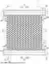
FIG. 1 is a front view of a heat exchanger according to the present embodiment.
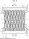
FIG. 2 is a partially enlarged view showing an enlarged attachment part of a side plate having an engagement portion in the front view of FIG. 1.
FIG. 3 is a partial perspective view showing a part of a side plate including an engagement portion and a part of a header tank to which the side plate is attached.
FIG. 4 is a partial perspective view showing a part of a side plate including an engagement portion (first modification) and a part of a header tank to which the side plate is attached.
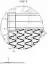
FIG. 5 is a partially enlarged view showing, instead of FIG. 2, an attachment part of a side plate having an engagement portion (second modification) in an enlarged manner.
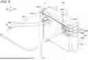
FIG. 6 is a partial perspective view showing a part of the side plate including the engagement portion (second modification) and a part of a header tank to which the side plate is attached.
DESCRIPTION OF EMBODIMENTS
Hereinafter, modes (present embodiments) for carrying out the present invention will be described in detail with reference to the drawings. In the following description, the same reference numerals denote parts having the same function, and redundant description in the drawings is appropriately omitted.
Overall Configuration of Heat Exchanger
As shown in FIG. 1, a heat exchanger 1 according to the present embodiment includes a heat exchange core portion 2 including a plurality of tubes 21 through which a heat medium flows, a pair of header tanks 3 provided at both ends in the extending direction (an arrow X direction in the drawing) of the tubes 21 and into which the tubes 21 are inserted, and a pair of side plates 4 provided in the outside at both ends in the stacking direction of the plurality of tubes 21. The heat exchanger 1 exchanges heat between a heat medium (including a refrigerant) flowing through the tube 21 via the header tank 3 and a fluid (e.g., air) passing between the plurality of tubes 21.
The tube 21 of the heat exchange core portion 2 is a tubular body extending in one direction (the arrow X direction in the drawing) and having a flat shape along a direction (an arrow Z direction in the drawing) intersecting the extending direction (the arrow X direction in the drawing). The plurality of the tubes 21 is disposed in parallel at predetermined intervals in a direction (the arrow Y direction in the drawing) intersecting the extending direction (the arrow X direction in the drawing), and a space between the plurality of tubes 21 serves as a passage path for a fluid to be heat-exchanged.
The fluid to be heat-exchanged flows in the direction of arrow Z in the drawing, and exchanges heat with the heat medium flowing in the tube 21 while passing between the plurality of tubes 21. In order to increase heat exchange efficiency, fins 22 (e.g., a corrugated fin) are usually provided in a space between the plurality of tubes 21 in the heat exchange core portion 2 and a space in the outside at both ends of the tubes 21 in the stacking direction (the arrow Y direction in the drawing). As described above, the heat exchange core portion 2 has a configuration in which the tubes 21 and the fins 22 are alternately stacked.
The header tank 3 includes a tubular tank member 31 that opens at both ends in the extending direction (the direction of arrow Y in the drawing) along the stacking direction of the tubes 21, and a pair of caps (tank caps) 32 that closes the opening (not shown). The tank member 31 includes a tank form body (upper tank) 31A and a coupling body (lower tank) 31B. By coupling the tank form body 31A to the coupling body 31B and closing both ends in the extending direction with the cap 32, a storage space of the heat medium is formed inside.
The end portion of the tube 21 in the extending direction (the arrow X direction in the drawing) is inserted into the coupling body (lower tank) 31B of the tank member 31, and after that, flux is applied and brazed to the connecting part with the tube 21 on the inner surface of the coupling body 31B. In this manner, the coupling body 31B and the tube 21 are connected to each other.
The pair of side plates 4 is provided between the pair of header tanks 3, and is connected to the cap 32 of the header tank 3. The heat exchange core portion 2 including the plurality of tubes 21 and a plurality of fins 22 is formed inside the pair of side plates 4. On a side surface 32A of the cap 32 of the header tank 3, a protruding portion 32B is provided.
The caps 32 at the same position in the extending direction (the direction of arrow Y in the drawing) of the pair of header tanks 3 are disposed such that the protruding portions 32B face each other, and mounted to the tank member 31. An engagement portion 43 described later of the side plate 4 is engaged with the protruding portion 32B of the cap 32.
As shown in FIG. 1, in the pair of header tanks 3, an inlet 33 is provided in a tank form body (upper tank) 31A of one (upper) header tank 3, and an outlet 34 is provided in a tank form body 31A of the other (lower) header tank 3. The heat medium flowing in from the inlet 33 flows to the tube 21 through the header tank 3 on one side (upper side), and the heat medium flowing through the tube 21 accumulates in the header tank 3 on the other side (lower side) and flows out from the outlet 34.
The side plate 4 includes a main body portion 41 extending along the extending direction of the plurality of tubes 21 (the arrow X direction in the drawing), and a pair of attachment portions 42 extending from both ends of the main body portion 41 in the extending direction along the extending direction of the header tank 3 (the arrow Y direction in the drawing) and attached to the side surface 32A of the cap 32 in the header tank 3. In addition, as shown in the enlarged view of FIG. 2, the main body portion 41 is disposed such that the surface on the opposite side to the side facing the attachment portion 42 is in contact with the fins 22 located in the outside at both ends of the heat exchange core portion 2 in the stacking direction (an arrow Y direction in the drawing) of the tubes 21. The heat exchange core portion 2 is supported by the pair of side plates 4 disposed in this manner.
Attachment of Side Plate 4
In the assembly of the heat exchanger 1 in the present embodiment, other configurations of the heat exchanger 1 are assembled before the side plate 4 is attached. Specifically, as shown in FIG. 1, first, the plurality of tubes 21 is disposed in parallel at predetermined intervals in a direction (the arrow Y direction in the drawing) intersecting the extending direction (the arrow X direction in the drawing), and the plurality of fins 22 is disposed between the plurality of tubes 21 and in the outside at both ends of the tube 21 in the stacking direction to form the heat exchange core portion 2.
Subsequently, both ends in the extending direction of the plurality of tubes 21 are inserted into the coupling bodies (lower tanks) 31B disposed at both ends in the extending direction of the plurality of tubes 21. Then, flux is applied to the connecting part of the inner surface of the coupling body 31B with the tube 21 and brazed, and this enables connecting the coupling body 31B to the tube 21. After that, the tank form body (upper tank) 31A is coupled to the coupling body 31B to form the tank member 31, and both ends in the extending direction (the direction of arrow Y in the drawing) of the tank member 31 are closed by the caps 32. The side plate 4 is attached to the configuration thus assembled.
As shown in FIGS. 1 and 2, the side plate 4 is attached to the side surface 32A of the cap 32 of the header tank 3 by the engagement portion 43 (FIG. 3) in a state where the main body portion 41 is disposed closer to the tube 21 side from the attachment portion 42.
Here, the engagement portion 43 of the side plate 4 will be described with reference to FIG. 3. In FIG. 3, components necessary for description are shown, and the illustrations are appropriately omitted. A first hole 43A of the engagement portion 43 extends from a boundary portion F between the main body portion 41 and the attachment portion 42 in the extending direction of the main body portion 41 (the direction opposite to the arrow X direction in the drawing).
The length in the extending direction (the direction opposite to the direction of arrow X in the drawing) and the width direction (the direction of arrow Z in the drawing) of the first hole 43A is slightly longer than the length in the extending direction (the direction opposite to the direction of arrow X in the drawing) and the width direction (the direction of arrow Z in the drawing) of the protruding portion 32B extending from the side surface 32A of the cap 32 as a starting point. The second hole 43B of the engagement portion 43 is connected to the first hole 43A at the boundary portion F and extends in the extending direction of the attachment portion 42 (the direction of arrow Y in the drawing). The length of the second hole 43B in the width direction (the arrow Z direction in the drawing) is slightly longer than the length of the protruding portion 32B in the width direction (the arrow Z direction in the drawing).
In the example of FIG. 3, two protruding portions 32B are provided at intervals on the side surface 32A of the cap 32. As shown in (a) and (b) in FIG. 3, the side plate 4 is provided at positions corresponding to the two protruding portion portions 32B with two of the engagement portions 43 described above spaced apart in a width direction (the arrow Z direction in the drawing) intersecting an extending direction (the arrow X direction in the drawing) of the main body portion 41. Note that the number (i.e., the number of the engagement portions 43 provided on the side plate 4) of the protruding portions 32B provided on the side surface 32A of the cap 32 is not limited to this, and may be singular or plural.
In order to attach the side plate 4 having the engagement portion 43 to the side surface 32A of the cap 32, first, the side plate 4 is disposed such that the main body portion 41 is closer to the tube 21 from the attachment portion 42, and between the pair of header tanks 3, the side plate 4 is moved from the outside of both ends in the stacking direction (the arrow Y direction in the drawing) of the tubes 21 and the fins 22 in the heat exchange core portion 2 toward the fins 22 at both ends in the stacking direction (until the side plate 4 comes into contact with the fins 22) such that the surface of the attachment portion 42 on a side opposite to a side facing the main body portion 41 comes into contact with a surface 32A-1 (FIG. 2) of the side surface 32A provided with the protruding portions 32B.
At this time, in the example of FIG. 3, the side plate 4 is moved in the direction opposite to the direction of arrow Y in the drawing with respect to the cap 32 of the header tank 3 attached to the heat exchange core portion 2. The extending direction (the direction opposite to the direction of arrow X in the drawing) of the protruding portion 32B is substantially perpendicular to the plane direction of the attachment portion 42 and substantially parallel to the extending direction of the first hole 43A (the direction opposite to the direction of arrow X in the drawing). With such an operation of the side plate 4, the protruding portion 32B in this state is disposed in the first hole 43A without interfering with the attachment portion 42, and then is disposed at the end portion in the extending direction (the direction of arrow Y in the drawing) of the second hole 43B via the first hole 43A ((a) in FIG. 3). After that, a tip 32B-1 of the protruding portion 32B is bent by caulking (e.g., thermal caulking), and the tip 32B-1 of the bent protruding portion 32B and the end portion in the extending direction of the second hole 43B are engaged and fixed ((b) in FIG. 3).
Note that, in (b) in FIG. 3, the tip 32B-1 of the protruding portion 32B is bent toward the direction of arrow Y in the drawing. However, the present invention is not limited to this example, and the tip 32B may be bent toward any direction as long as the direction is a direction in which the tip 32B-1 is engaged with the second hole 43B. For example, the tip may be bent toward the direction of arrow Z in FIG. 3 or the opposite direction.
As described above, in the present embodiment, the side plate 4 having the engagement portion 43 including the first hole 43A and the second hole 43B can be easily attached to the side surface 32A of the cap 32 of the header tank 3 without interfering with the protruding portion 32B of the cap 32. That is, in the present embodiment, the heat exchanger 1 in which the side plate 4 is suitably connected without interfering with the side surface of the header tank 3 can be formed.
In the following, a first and second modifications of the present embodiment will be described. In the first and second modifications, the description of the same contents as those of the foregoing embodiment will be omitted. In addition, also in FIGS. 4 and 6, similarly to FIG. 3, only components necessary for description are shown, and the illustrations are appropriately omitted.
First Modification
In the first modification, the heat exchanger 1 includes a side plate 4A provided with two engagement portions 43 shown in (a) and (b) in FIG. 4 instead of the two engagement portions 44 shown in FIG. 3. The engagement portion 44 of the side plate 4A shown in FIG. 4 includes a first hole 44A extending from the end portion of an attachment portion 42A on a side opposite to the main body portion 41 side (boundary portion F side) in the extending direction of the attachment portion 42A (a direction opposite to a direction of arrow Y in the drawing), and a second hole 44B connected to the first hole 44A and extending in a direction intersecting the extending direction of the first hole 44A in the attachment portion 42A (a width direction of the attachment portion 42A (a direction of arrow Z in the drawing)).
The length of the first hole 44A in the width direction (the arrow Z direction in the drawing) is slightly longer than the length of the protruding portion 32B extending from the side surface 32A of the cap 32 as a starting point in the width direction (the arrow Z direction in the drawing). The length of the second hole 44B in the width direction (the arrow Y direction in the drawing) is slightly longer than the length of the protruding portion 32B in the height direction (the arrow Y direction in the drawing).
In the first modification, unlike the above example, the heat exchanger 1 is assembled as follows. Specifically, the attachment portion 42A of the side plate 4A is attached to the cap 32 in advance. Here, the side plate 4A is attached to the side surface 32A of the cap 32 by the engagement portion 44 in a state where the main body portion 41 is disposed closer to the tube 21 from the attachment portion 42A.
Subsequently, the heat exchange core portion 2 is formed by the plurality of tubes 21 and the plurality of fins 22, and both ends of the plurality of tubes 21 in the extending direction are inserted into the coupling body (lower tank) 31B. Then, after flux is applied to the connecting part of the inner surface of the coupling body 31B with the tube 21 and the coupling body 31B and the tube 21 are connected, the tank form body (upper tank) 31A is coupled to the coupling body 31B to form the tank member 31.
After that, both ends of the tank member 31 are closed with caps 32. Since the cap 32 is attached to both ends of the side plate 4A in the extending direction, two upper and lower openings are simultaneously closed at both ends of the pair of upper and lower tank members 31 connected to the heat exchange core portion 2 in the extending direction (the direction of arrow Y in the drawing).
In order to attach the side surface 32A of the cap 32 to the side plate 4A having the engagement portion 44, as shown in FIG. 4, the side plate 4A is disposed such that the main body portion 41 is closer to the tube 21 from the attachment portion 42A, and the cap 32 is moved with respect to the side plate 4A such that the protruding portion 32B is disposed in the second hole 44B via the first hole 44A while the surface 32A-1 (FIG. 2) of the side surface 32A provided with the protruding portion 32B is brought into contact with the surface of the attachment portion 42A on the opposite side to the side facing the main body portion 41. Note that needless to say, the side plate 4A may be moved with respect to the cap 32, and in this case, the same attachment can be performed.
At this time, in the example of FIG. 4, the cap 32 is moved in the direction opposite to the direction of arrow Y in the drawing and then moved in the direction of arrow Z in the drawing with respect to the side plate 4A. The extending direction (the direction opposite to the direction of arrow X in the drawing) of the protruding portion 32B is substantially perpendicular to the plane direction of the attachment portion 42A. With such an operation of the cap 32 in this state, the protruding portion 32B is disposed from the end portion on the side opposite to the main body portion 41 side (boundary portion F side) in the first hole 44A to the end portion in the extending direction (the direction opposite to the direction of arrow Y in the drawing) without interfering with the attachment portion 42A, and then disposed to the end portion in the extending direction (the direction of arrow Z in the drawing) in the second hole 44B via the first hole 44A.
After the protruding portion 32B is disposed at the end portion in the extending direction (the direction of arrow Z in the drawing) of the second hole 44B via the first hole 44A in this manner ((a) in FIG. 4), the tip 32B-1 of the protruding portion 32B is bent by caulking (e.g., thermal caulking), and the tip 32B-1 of the bent protruding portion 32B and the end portion in the extending direction of the second hole 44B are engaged and fixed ((b) in FIG. 4).
In the example of (b) in FIG. 4, the tip 32B-1 of the protruding portion 32B is bent toward the direction of arrow Y in the drawing. However, the present invention is not limited to this example, and the tip 32B-1 may be bent toward any direction as long as the tip 32B-1 is engaged with the second hole 44B. For example, the tip may be bent toward the direction of arrow Z in FIG. 4 or the direction opposite to the direction of arrow Y in FIG. 4.
As described above, in the first modification, the side plate 4A having the engagement portion 44 including the first hole 44A and the second hole 44B can be easily attached to the side surface 32A of the cap 32 of the header tank 3, and the heat exchanger 1 in which the side plate 4A is suitably connected without interfering with the side surface of the header tank 3 can be formed.
Second Modification
In a second modification, the heat exchanger 1 includes a side plate 4B of FIGS. 5 and 6 instead of the side plate 4 of FIG. 3. The side plate 4B has a configuration basically similar to that of the side plate 4A in FIG. 4. However, a length of an attachment portion 42B in the extending direction (the direction opposite to direction of arrow Y in FIGS. 5 and 6) is shorter than a length of the attachment portion 42A of the side plate 4A in FIG. 4 in the extending direction (the arrow Y direction in FIG. 4), and is substantially the same as a length of the side surface 32A of the cap 32 in the extending direction (the direction opposite to the direction of arrow Y in FIGS. 5 and 6).
The engagement portion 45 of the side plate 4B includes a first hole 45A extending in the extending direction of the attachment portion 42B (the direction of arrow Y in FIG. 6) from the end portion of the attachment portion 42B on the side opposite to the main body portion 41 side (the boundary portion F side), and a second hole 45B connected to the first hole 45A and extending in the direction intersecting the extending direction of the first hole 45A in the attachment portion 42B (the width direction of the attachment portion 42B (the direction of arrow Z in FIG. 6)).
In the second modification, the side plate 4B having a configuration basically similar to that of the side plate 4A of the first modification is different from the disposed state of the side plate 4A, and the attachment portion 42B is disposed closer to the tube 21 from the main body portion 41. By disposing the side plate 4B in this manner, the side plate 4B can be attached to the side surface 32A of the cap 32 of the header tank 3 attached to a heat exchange core portion 2B, similarly to FIGS. 1 to 3 of the foregoing embodiment.
That is, in the second modification, as similar to the examples of FIGS. 1 to 3 of the foregoing embodiment, other components of the heat exchanger 1 are assembled before the side plate 4B is attached. As shown in FIGS. 5 and 6, the side plate 4B is attached to the side surface 32A of the cap 32 by the engagement portion 45 in a state where the attachment portion 42B is disposed closer to the tube 21 from the main body portion 41. The heat exchanger 1 of the modification 2 includes the heat exchange core portion 2B having alternately tubes 21 and fins 22 more than the heat exchange core portion 2 of FIG. 2.
In order to attach the side plate 4B having the engagement portion 45 to the side surface 32A of the cap 32, as shown in FIGS. 5 and 6, first, the side plate 4B is disposed such that the attachment portion 42B is closer to the tube 21 from the main body portion 41, and between the pair of header tanks 3, the side plate 4B is moved from the outside of both ends in the stacking direction (the direction of arrow Y in the drawing) of the tubes 21 and the fins 22 in the heat exchange core portion 2B toward the fins 22 at both ends in the stacking direction (until the side plate 4B comes into contact with the fins 22) such that the surface of the attachment portion 42B on the side opposite to the side facing the main body portion 41 comes into contact with the surface 32A-1 (FIG. 5) of the side surface 32A provided with the protruding portions 32B.
At this time, in the example of FIG. 6, with respect to the cap 32 of the header tank 3 attached to the heat exchange core portion 2B, the side plate 4B is moved in the direction opposite to the direction of arrow Y in the drawing and then moved in the direction opposite to the direction of arrow Z in the drawing. The extending direction (the direction opposite to the arrow X direction in the drawing) of the protruding portion 32B is substantially perpendicular to the plane direction of the attachment portion 42B. By such an operation of the side plate 4B in this state, the protruding portion 32B is disposed from the end portion on the opposite side to the main body portion 41 side (boundary portion F side) in the first hole 45A to the end portion in the extending direction (the arrow Y direction in the drawing) without interfering with the attachment portion 42B, and then is disposed to the end portion in the extending direction (the arrow Z direction in the drawing) in the second hole 45B via the first hole 45A((a) in FIG. 6).
Then, the tip 32B-1 of the protruding portion 32B is bent by caulking (e.g., thermal caulking), and the tip 32B-1 of the bent protruding portion 32B and the end portion of the second hole 45B in the extending direction (the arrow Z direction in the drawing) are engaged and fixed ((b) in FIG. 6).
In the example of (b) in FIG. 6, the tip 32B-1 of the protruding portion 32B is bent toward the direction of arrow Y in the drawing. However, the present invention is not limited to this example, and the tip 32B-1 may be bent toward any direction as long as the tip 32B-1 is engaged with the second hole 45B. For example, the tip 32B-1 may be bent toward the direction of arrow Z in FIG. 6 or the direction opposite to the direction of arrow Y in FIG. 6.
As described above, in the second modification, the side plate 4B having the engagement portion 45 including the first hole 45A and the second hole 45B can be easily attached to the side surface 32A of the cap 32 of the header tank 3 without interfering with the protruding portion 32B of the cap 32. That is, in the second modification, the heat exchanger 1 in which the side plate 4B is suitably connected without interfering with the side surface of the header tank 3 can be formed.
As described above, although the present embodiment and the modifications have been described in detail with reference to the drawings, the specific configuration is not limited to the above-described example, and changes in design and the like without deviating from the gist of the present invention are also included in the present invention.
In the foregoing embodiment, the first modification, and the second modification, an example in which the side plates 4, 4A, and 4B are attached to the side surface 32A of the cap 32 in the header tank 3 has been described. However, the present invention is not limited to this example. For example, the side plates 4, 4A, and 4B may be attached to the side surface of the coupling body (lower tank) 31B in the header tank 3. Also in this case, the side plates 4, 4A, and 4B can be easily attached to the side surface of the coupling body 31B without interfering with a protruding portion (not shown) provided on the side surface of the coupling body 31B.
LIST OF REFERENCE SIGNS
-
- 1 Heat exchanger
- 2, 2B Heat exchange core portion
- 3 Header tank
- 4, 4A, 4B Side plate
- 21 Tube
- 22 Fin
- 31 Tank member
- 31A Tank form body (upper tank)
- 31B Coupling body (lower tank)
- 32 Cap (tank cap)
- 32A Side surface
- 32A-1 Surface provided with protruding portion 32B of side surface 32A
- 32B Protruding portion
- 32B-1 Tip
- 33 Inlet
- 34 Outlet
- 41 Main body portion
- 42, 42A, 42B Attachment portion
- 43 to 45 Engagement portion
- 43A, 44A, 45A First hole
- 43B, 44B, 45B Second hole
- F Boundary portion
Claims
1. A heat exchanger comprising:
a plurality of tubes through which a heat medium flows;
a pair of header tanks provided at both ends in an extending direction of the tube and into which the tube is inserted; and
a pair of side plates provided in an outside at both ends in a stacking direction of the plurality of tubes, wherein
the side plate includes an engagement portion that engages with a protruding portion provided on a side surface of the header tank.
2. The heat exchanger according to claim 1, wherein
the header tank includes a tubular tank member that opens at both ends in an extending direction along a stacking direction of the tubes, and a pair of caps that closes the opening, and
the engagement portion engages with the protruding portion provided on a side surface of the cap.
3. The heat exchanger according to claim 1, wherein
the side plate includes a main body portion extending along an extending direction of the tube, and a pair of attachment portions extending from both ends in an extending direction of the main body portion along an extending direction of the header tank and attached to side surfaces of the header tank by the engagement portions, and
the main body portion is disposed closer to the tube from the attachment portion.
4. The heat exchanger according to claim 3, wherein
the engagement portion includes a first hole extending from a boundary portion between the main body portion and the attachment portion in an extending direction of the main body portion and a second hole connected to the first hole and extending in an extending direction of the attachment portion, and
the protruding portion is disposed in the second hole via the first hole by moving the side plate toward the tube from an outside at both ends in a stacking direction of the tube, and the second hole is engaged with a tip of the protruding portion by caulking.
5. The heat exchanger according to claim 3, comprising a plurality of fins disposed between the plurality of tubes and an outside at both ends in a stacking direction of the tubes, wherein
the main body portion is disposed in contact with the fins located in the outside at the both ends of the tube in the stacking direction.
Images & Drawings included:


Sources:
- United States Patent and Trademark Office - verify current appl. status at the USPTO↗
Similar patent applications:
- » 20130118720
HEAT EXCHANGING ELEMENT FOR A HEAT EXCHANGER, METHOD OF MANUFACTURING A HEAT EXCHANGING ELEMENT FOR A HEAT EXCHANGER, HEAT EXCHANGER, AND RETROFITTING METHOD FOR A HEAT EXCHANGER - » 20200318855
Heat exchanger pipe, method of manufacturing heat exchanger pipe, heat exchanger fin, elliptical heat exchanger pipe, and hot water storage type heat exchanger having elliptical heat exchanger pipe - » 20180245863
Heat exchanger, heat exchange method using heat exchanger, heat transport system using heat exchanger, and heat transport method using heat transport system - » 20180238634
Heat exchange system with main heat exchange chamber and subsidiary heat exchange chamber and method for exchanging heat by using the heat exchange system - » 20060086486
Heat exchanger, heat exchanger tube member, heat exchanger fin member and process for fabricating the heat exchanger - » 20080105415
Chamber For Holding A Fluid For A Heat Exchanger, Heat Exchanger, More Particularly For A Heat Exchange Unit, And A Heat Exchange Unit, In Particular In The Form Of A Monoblock - » 20060059946
Finned tube for heat exchangers, heat exchanger, apparatus for fabricating heat exchanger finned tube and process for fabricating heat exchanger finned tube - » 10492206
Finned tube for heat exchangers, heat exchanger, process for producing heat exchanger finned tube, and process for fabricating heat exchanger - » 20180238633
Heat exchange system with a heat exchange chamber in with a thermal insulation layer, method for manufacturing the heat exchange system and method for exchanging heat by using the heat exchange system - » 20220390180
Heat exchange member, heat exchanger using heat exchange member, and method of manufacturing heat exchange member
Recent applications in this class:
- » 20260110461 2026-04-23
SUPERHEAT CONTROLLED THERMAL STORAGE - » 20260071787 2026-03-12
HVAC WITH BACK-PRESSURE LIMITING EXPANSION DEVICE - » 20260016201 2026-01-15
THERMODYNAMIC HEAT RECOVERY WITHOUT AN ADDITIONAL THERMODYNAMIC CIRCUIT - » 20260002708 2026-01-01
HEAT SOURCE APPARATUS AND REFRIGERATION CYCLE APPARATUS - » 20260002707 2026-01-01
HFO-1234ZE, HFO-1225ZC AND HFO-1234YF COMPOSITIONS AND PROCESSES FOR PRODUCING AND USING THE COMPOSITIONS - » 20260002706 2026-01-01
Systems and Methods for Vapor Compression Systems with a Multi-Circuit Heat Exchanger and a Low Cost Distributor - » 20250341347 2025-11-06
TURBOEXPANSION REVERSIBLE HEAT PUMP CYCLE - » 20250290671 2025-09-18
Direct Expansion Evaporator Coil with Ejector Capacity Boost for Low Liquid Temperature and Economized Systems - » 20250264252 2025-08-21
HEAT EXCHANGE SYSTEM AND HEAT EXCHANGE METHOD - » 20250237414 2025-07-24
MODULAR CHILLER
Recent applications for this Assignee:
- » 20260155704 2026-06-04
ELECTRIC COMPRESSOR - » 20260138418 2026-05-21
VEHICLE AIR CONDITIONING DEVICE - » 20260131634 2026-05-14
VEHICLE AIR CONDITIONING DEVICE - » 20260131632 2026-05-14
VEHICLE AIR-CONDITIONING DEVICE - » 20260055941 2026-02-26
REFRIGERANT CIRCUIT UNIT - » 20240159421 2024-05-16
AIR CONDITIONING APPARATUS - » 20240157761 2024-05-16
VEHICLE AIR CONDITIONING APPARATUS - » 20240072645 2024-02-29
INVERTER DEVICE - » 20240060494 2024-02-22
Scroll compressor with a thrust plate and a flexible thrust sheet member - » 20240026882 2024-01-25
Scroll compressor with suppressed reduction of rotational moment