Firearm Corrective Vision Devices, Assemblies, and Apparatuses
US20260168765A1
2026-06-18
18/983,733
2024-12-17
Smart Summary: Firearm corrective vision devices help improve the aim of shooters who need vision correction. They include a special lens placed between a cap and a housing that can be attached to a gun. The assembly consists of a frame that holds the lens and connects to the front part of a gun sight. Additionally, the apparatus is designed to fit over the gun sight, keeping the lens close to it and protected by a cap. Overall, these devices enhance shooting accuracy for people with vision issues. 🚀 TL;DR
Abstract:
Described herein are embodiments of firearm corrective vision devices, assemblies, and apparatuses. A firearm corrective vision device may comprise a corrective medium between a cap and a housing connected to a base attachable to a firearm. A firearm corrective vision assembly may comprise a frame configured to house a corrective medium and attach to a proximal end of a firearm sight and a cap configured to affix to the housing and cover the corrective medium. A firearm corrective vision apparatus may comprise a frame configured to attach over a firearm sight and house a corrective medium proximal to the firearm sight with a cap affixed to the frame covering the corrective medium.
Applicant:
Interested in similar patents?
Get notified when new applications in this technology area are published.
Classification:
F41G1/26 » CPC main
Sighting devices; Rearsights; Adjusting mechanisms therefor; Mountings therefor screw
F41G1/28 » CPC further
Sighting devices; Rearsights; Adjusting mechanisms therefor; Mountings therefor wedge; cam; eccentric
Description
FIELD OF THE INVENTION
Described herein are embodiments of firearm corrective vision devices, assemblies, and apparatuses.
BACKGROUND OF THE INVENTION
Safe operation of a firearm traditionally requires the user to display sufficient visual perception to appropriately manipulate, direct, and aim the firearm. However, a significant number of individuals may experience varying degrees of visual impairment, which may be otherwise readily correctable via a corrective medium. A corrective medium may include, for example and without limitation, spectacles, glasses, contacts, custom lenses, and/or prescription lenses. Certain corrective lenses can be commonly worn in the form of glasses. Attempting to operate a firearm without a corrective medium, for individuals who generally require a corrective medium, may be disadvantageous due to inherent risk of operating a firearm with visual impairment (e.g., increased chance of targeting and/or shooting an unintended being or item). Vision impairment may affect, for example, minute of angle at various ranges or other measure of accuracy or precision in attempted firearm operation. Attempting to operate a firearm with a traditional corrective medium, such as glasses, may be disadvantageous due to risk of harm to the glasses, and/or harm to the user resulting from damaged glasses (e.g., because of sharp glass fragments or shards). Certain traditional corrective medium examples are also disadvantageous due to various environmental factors, such as debris interfering with glasses and/or contacts, etc. Attempting to operate a firearm with a traditional corrective medium can also be less than ideal due to focal point non-optimization relative to the operator's eye when attempting to focus on a target, firearm sight, or both.
Traditional corrective media such as lenses are manufactured to refract light in a manner and to a degree that compensates for a user's visual impairment, effectively correcting their sight perception. Accordingly, traditional corrective media operate as intended at a particular focal point distance relative to the user and the target object(s) to be perceived. Corrective media may have different shapes, such as, for example, double convex lens, double concave lens, positive meniscus lens, negative meniscus lens, Plano-convex lens, and Plano-concave lens. A user may have prescription lenses manufactured to account for different focal point positioning, such as if the lens were to be placed at a further distance from the user's face than conventional glasses (e.g., placement for use in conjunction with a sight on a firearm). A user may dispose optical lenses to help better visualize certain elements of a firearm sight on the firearm barrel, as discussed by Semaan in U.S. Patent Application Publication No. 2022/0034628 A1. However, notably lacking in existing technologies and prior art are adequate methods for deploying a corrective medium along a firearm to be used—with or without additional firearm sight(s)—in connection with correcting an operator's perception of a sight picture in its entirety (e.g., including visualizing a downfield intended target), for adequate firearm operation (e.g., including aiming and/or shooting).
The embodiments described herein address shortcomings in the prior art and current technologies described above.
SUMMARY OF THE INVENTION
The embodiments described herein overcome particular problems in the prior art related to vision correction particularly in the context of firearms.
In certain embodiments, a firearm corrective vision device may comprise a cap, housing, and base. A corrective medium may be disposed between the cap and housing. The housing may be connected to the base. The base may be attachable to a firearm or sight.
A device may comprise a corrective medium between a cap and a housing connected to a base attachable to a firearm or sight.
The base may comprise a platform having a first ledge opposite a second ledge, forming a first track between the platform and the first ledge and a second track between the platform and the second ledge, with the first track and the second track configured to engage opposite sides of a rail of the firearm. Certain embodiments may further comprise a latch to interlock the rail. The latch may comprise a screw disposed orthogonal to the first track and the second track.
The housing may be rotatably connected to the base. A dowel may intersect the housing and the base.
The housing may comprise a first face having a first recess, a second face having a second recess, and a surface channel between the first recess and the second recess, and the base may comprise a spring loaded plunger with a promontory, further wherein in a first configuration the promontory engages the first recess, in a second configuration the promontory engages the second recess, and in transition between the first configuration and the second configuration the promontory engages the surface channel. The first face may be orthogonal to the second face.
The corrective medium may comprise a vertical axis perpendicular to a principal axis further wherein the vertical axis is parallel to a projectile barrel of the firearm in a first configuration and the principal axis is parallel to the projectile barrel in a second configuration.
The device may further comprise a first cushion apposing the housing and the corrective medium and a second cushion apposing the corrective medium and the cap. The first cushion may comprise a first ring, the second cushion may comprise a second ring, the housing may comprise a first slot configured to receive the first ring, and the cap may comprise a second slot configured to receive the second ring.
In certain embodiments, at least one fastener affixes the cap to the housing. In certain embodiments, at least one fastener may be selected from the group consisting of adhesive, bolt, glue, latch, nail, rivet, tape, and screw.
In certain embodiments, the corrective medium may comprise a vertex having an inlet, the housing may comprise a crest having a tab, and the tab may occupy the inlet.
In certain embodiments, the device further comprises a first cover along the housing external to the corrective medium and a second cover along the cap external to the corrective medium.
In exemplary embodiments, the first cover, second cover, or both may comprise at least one material selected from the group consisting of acrylic, polycarbonate, polymethyl methacrylate, and thermoplastic polymer.
In exemplary embodiments, the first cushion, second cushion, or both may comprise at least one material selected from the group consisting of ethylene propylene diene monomer, fluorocarbon, neoprene, nitrile, polytetrafluoroethylene, propylene, rubber, and silicone.
In exemplary embodiments, a base, cap, housing, or combination thereof may comprise at least one material selected from the group consisting of acetal homopolymer, acrylonitrile butadiene styrene, laurolactam monomer, nylon polymer, and polyoxymethylene.
A firearm corrective vision assembly may comprise a corrective medium with a principal axis, a frame configured to house the corrective medium and attach to a proximal end of a firearm sight wherein the principal axis aligns with an optical axis of the firearm sight, and a cap configured to cover the corrective medium and affix to the housing.
A firearm corrective vision apparatus may comprise a corrective medium with a principal axis, a cap that covers the corrective medium and affixes to a frame, wherein the frame houses the corrective medium and attaches over a firearm sight such that the corrective medium is proximal to a proximal end of the firearm sight and the principal axis aligns with an optical axis of the firearm sight.
In embodiments herein, a corrective medium may comprise one or more bifocals, glasses, eyeglasses, sunglasses, lenses, custom lenses, prescription lenses, shades, goggles, spectacles, and/or monocles, etc. A corrective medium may be polarized and/or tinted.
BRIEF DESCRIPTION OF THE DRAWINGS
Other features of embodiments disclosed herein will become apparent from the attached drawings. The following drawings are illustrative examples and do not further limit any claims that may eventually issue. For purposes of explanation, several embodiments are set forth in the following figures, wherein:
FIG. 1A is an oblique front view of a base of a firearm corrective vision device in a particular embodiment;
FIG. 1B is an oblique rear view of a base of a firearm corrective vision device in a particular embodiment;
FIG. 1C is an oblique bottom view of a base of a firearm corrective vision device in a particular embodiment;
FIG. 2A is an oblique front view of a housing of a firearm corrective vision device in a particular embodiment;
FIG. 2B is an oblique rear view of a housing of a firearm corrective vision device in a particular embodiment;
FIG. 3A is an oblique front view of a cap of a firearm corrective vision device in a particular embodiment;
FIG. 3B is an oblique rear view of a cap of a firearm corrective vision device in a particular embodiment;
FIG. 4 is an oblique view of a corrective medium for firearm corrective vision device embodiments;
FIG. 5 is an oblique view of a firearm for firearm corrective vision device embodiments;
FIG. 6 schematizes an expanded view of a firearm corrective vision device embodiment with a firearm;
FIG. 6A shows a front view of an integrally connected base and housing of a particular embodiment of a firearm corrective vision device;
FIG. 6B shows a rear view of an integrally connected base and housing of a particular embodiment of a firearm corrective vision device;
FIG. 7 schematizes a firearm with an expanded view of an exemplary embodiment of a firearm corrective vision device;
FIG. 7A shows a base and a housing of a firearm corrective vision device connected in a first configuration in a particular embodiment;
FIG. 7B shows a base and a housing of a firearm corrective vision device connected in a second configuration in a particular embodiment;
FIG. 8A schematizes components of a firearm corrective vision assembly embodiment in a first oblique view;
FIG. 8B schematizes components of a firearm corrective vision assembly embodiment in a second oblique view; and
FIG. 9 schematizes a firearm corrective vision apparatus embodiment.
DETAILED DESCRIPTION
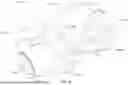
FIGS. 1A-C depict a base 101 of a firearm corrective vision device in a particular embodiment. Base 101 has a front 101a, rear 101b, top 101c, and bottom 101d; and FIGS. 1A-C show base 101 in oblique front, side, and bottom views, respectively. Base 101 has a platform 111 with a first ledge 112a opposite a second ledge 112b, which respectively form a first track 113a (between platform 111 and first ledge 112a) and a second track 113b (between platform 111 and second ledge 112b). In exemplary embodiments, base 101 comprises a spring loaded plunger with a promontory (not illustrated), which may be disposed in a plunger cavity 116a, best seen in FIG. 1A. In further embodiments, a dowel (not drawn) may traverse a first dowel hole 115a and a second dowel hole 115b, best depicted in FIG. 1A. Certain firearm corrective vision devices may further comprise a latch (not illustrated), which may traverse a first latch hole 114a and a second latch hole 114b along a latch cavity 114c, best shown in FIG. 1C.
FIGS. 2A-B show a housing 102 of a firearm corrective vision device in a particular embodiment. Housing 102 has a front 102a, rear 102b, top 102c, and bottom 102d; and FIGS. 2A-B depict housing 102 in oblique front and rear views, respectively. Housing 102 has a first face 121 with a first recess 123, a second face 122 with a second recess 124, and a surface channel 127 between first recess 123 and second recess 124. As seen in FIG. 2A, certain embodiments of housing 102 comprise a first lip 128 to appose a first cover (not illustrated). As seen in FIG. 2B, certain embodiments of housing 102 may comprise a fist slot 126 to appose a first cushion (not shown). Other embodiments of housing 102 may also comprise a plurality of protrusions 125; as configured in FIG. 2B, protrusions 125 may be located toward rear 102b and top 102c. Certain firearm corrective vision devices may further comprise one or more fasteners to affix housing 102 to a cap (not drawn in FIGS. 2A-B). Fasteners may comprise, for example, bolts with nuts-in exemplary embodiments, as illustrated in FIGS. 2A-B, housing 102 may comprise one or more nut holes 131b at front 102a to house nuts (not drawn) and one or more bolt cavities 131c between front 102a and rear 102b to house stems of bolts (not drawn). In certain embodiments, a dowel (not drawn) may traverse a dowel channel 115c. Further exemplary embodiments of housing 102, as illustrated in FIG. 2B, may comprise a crest 129a, at top 102c, having a tab 129b configured to occupy an inlet at a vertex of a corrective medium (not drawn).
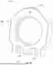
FIGS. 3A-B illustrate a cap 103 of a firearm corrective vision device in a particular embodiment. Cap 103 has a front 103a, rear 103b, top 103c, and bottom 103d; and FIGS. 3A-B show cap 103 in oblique front and rear views, respectively. As seen in FIG. 3A, certain embodiments of cap 103 may comprise a second slot 137 to appose a second cushion (not shown). As seen in FIG. 3B, certain embodiments of cap 103 comprise a second lip 139 to appose a second cover (not illustrated). Other embodiments of cap 103 may also comprise a plurality of protrusion receivers 135; as configured in FIG. 3A, protrusion receivers 135 may be located toward front 103a and top 103c. Some firearm corrective vision devices may comprise one or more fasteners to affix a housing to cap 103, such as via bolts with nuts. In further embodiments, cap 103 may comprise one or more bolt holes 131a at rear 103d (e.g. as shown in FIG. 3B) to house heads of bolts (not drawn).
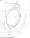
FIG. 4 depicts a corrective medium 104 for a firearm corrective vision device in a particular embodiment. Corrective medium 104 may comprise one or more bifocals, glasses, eyeglasses, sunglasses, lenses, corrective lenses, custom lenses, optical lenses, prescription lenses, shades, goggles, spectacles, and/or monocles, etc. Corrective medium 104 may be polarized and/or tinted. In exemplary embodiments, corrective medium 104 may comprise a lens, as illustrated in FIG. 4. Corrective medium 104 has front 104a, rear 104b, top 104c, and bottom 104d; and FIG. 4 shows corrective medium 104 in an oblique view. Corrective medium 104 comprises a vertical axis 141 (in the direction of bottom 104d to top 104c) and principal axis 142 (in the direction of rear 104b to front 104a). In certain embodiments, corrective medium 104 may further comprise a vertex 144, at top 104c, having an inlet 143 configured to receive a tab of a cap. Corrective media according to embodiments herein may include, without limitation, a double convex lens, double concave lens, positive meniscus lens, negative meniscus lens, Plano-convex lens, and/or Plano-concave lens, for example.
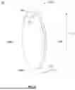
FIG. 5 depicts a schematized firearm 105 for or with which firearm corrective vision device embodiments can be used. FIG. 5 shows an oblique view and firearm 105 has front 105a, rear 105b, top 105c, and bottom 105d. Firearm 105 should comprise a projectile barrel 152 with rail 151 (at top 105c), both oriented along optical axis 153 (in the direction of rear 105b to front 105a). Embodiments herein may be used for or with a firearm having a sight, such as firearm 105 depicted in FIG. 5. And certain embodiments herein may be used for or with a firearm not having a sight. In embodiments herein, a sight may comprise a scope. Firearm 105 and firearms depicted or discussed herein may look like a long gun, such as a rifle or shotgun, which is done for exemplary purposes and is not limiting. Persons of skill in the art will readily see other firearms within the scope, which may include, without limitation, a long gun, rifle, shotgun, handgun, pistol, revolver, musket, arabesque, carbine, riot gun, sniper rifle, assault rifle, battle rifle, submachine gun, and/or machine gun, whether single-shot, manual repeating, semi-automatic, automatic, single-action, double-action, double-action/single-action, single-shot, break-action, bolt-action, lever-action, compact, short barreled, long barreled, double barreled, smooth bore, rifle bore, grooved bore, spiral bore, and/or spiral grooved bore, as applicable. Firearms within the scope may also include any firearm, or other weapon, whether for hunting, recreational, or other purpose, including but not limited to a toy gun, pellet gun, air gun, BB gun, laser gun, laser tag gun, paintball gun, dart gun, foam dart gun, squirt gun, or water gun.
Persons having ordinary skill in the art will readily appreciate various embodiments of firearm corrective vision devices in accordance with the descriptions herein.
A firearm corrective vision device 100 may comprise a corrective medium 104 between a cap 103 and a housing 102 connected to a base 101 attachable to a firearm 105. Schematized in FIG. 6 is an expanded view of an embodiment of a device 100. Housing 102 may be integrally connected to or with base 101 in certain embodiments, such as FIGS. 6A-B. In alternate embodiments, however, the housing 102 and base 101 could be variably connected. In exemplary embodiments, a housing 102 and base 101 may be rotatably connected, such as FIGS. 7A-B.
Returning to FIG. 6, in certain embodiments, base 101 is attachable to a firearm 105 at a rail 151, such as a Picatinny rail having two sides. In certain embodiments, base 101's platform 111 can slide along the top of rail 151 between rear 105b and front 105a, but is prevented from unintended orthogonal translation (whether sideways or upwards thereby disengaging rail 151) because the sides of rail 151 are engaged within first track 113a and second track 113b and secured between the platform 111 and the first and second ledges 112a, 112b. This allows positioning of device 100 at an optimal or desired location along rail 151 to allow for appropriate distance between a user's eye and corrective medium 104 during firearm use, and/or positioning as desired in relation to one or more other accessories or components along rail 151 or firearm 105. In exemplary embodiments, device 100 can be secured in place once the ideal location along rail 151 is selected. For example, a device 100 may comprise a latch to interlock rail 151. In certain embodiments, the latch may comprise a screw non-parallel to first track 113a and second track 113b. In some embodiments, the latch may comprise a 30 mm M5 screw. Persons of ordinary skill in the art will readily appreciate the latch may comprise a bolt, grip, or other item or alternative. A latch may traverse first latch hole 114a, second latch hole 114b, and intervening latch cavity 114c, in certain embodiments. A latch may simply comprise a screw or bolt to be tightened against the side of a rail 151 (e.g., at a flat or nearly flat surface) to promote fixation via friction forces.
FIGS. 6A-B depict an integrally connected base 101 and housing 102 in accord with certain embodiments of firearm corrective vision devices. FIGS. 6A-B show base 101 and housing 102 in oblique front and rear views, respectively, having front 100a, rear 100b, top 100c, and bottom 100d. Similar to FIGS. 1A-C, base 101 has a platform 111 with a first ledge 112a opposite a second ledge 112b, which respectively form a first track 113a (between platform 111 and first ledge 112a) and a second track 113b (between platform 111 and second ledge 112b). Certain embodiments comprise a latch (not illustrated), which may traverse a first latch hole 114a and a second latch hole 114b along a latch cavity 114c. Similar to FIGS. 2A-B, housing 102 has a first lip 128 to appose a first cover (not illustrated) and a fist slot 126 to appose a first cushion (not shown). Certain embodiments comprise a plurality of protrusions 125; which may be located toward rear 100b and top 100c. Certain embodiments comprise one or more fasteners to affix housing 102 to a cap (not drawn in FIGS. 6A-B), and housing 102 may comprise one or more nut holes 131b at front 100a to house nuts (not drawn) and one or more bolt cavities 131c between front 100a and rear 100b to house stems of bolts (not drawn). Further embodiments of housing 102 may comprise a crest 129a, at top 100c, having a tab 129b configured to occupy an inlet at a vertex of a corrective medium (not drawn).
In certain embodiments, as illustrated in FIG. 6, housing 102 may be in front of cap 103 along firearm 105—i.e., cap 103 may be relatively nearer to the rear 105b of firearm 105, and/or housing 102 may be relatively nearer to the front 105a of firearm 105. In such embodiments, the fronts 101a, 102a, 103a of base 101, housing 102, and cap 103 (as oriented and defined in FIGS. 1A-3B) could face and/or point toward the front 105a of firearm 105 along optical axis 153.
However, in other embodiments, components of device 100 may be differently arranged and/or oriented—both with respect to each other and/or with respect to firearm 105—as will be readily apparent to persons having ordinary skill in the art. As such, unless context clearly indicates otherwise, the terms “front” and/or “rear” herein are used for the purpose of explaining certain components in certain embodiments, and shall not dictate, limit, mandate, or necessitate any one arrangement, configuration, order, or sequence.
As shown in FIG. 7, for instance, in certain exemplary embodiments of device 100 the housing 102 may be behind the cap 103 along firearm 105—e.g., housing 102 may be relatively nearer to the rear 105b of firearm 105, and/or cap 103 may be relatively nearer to front 105a of firearm 105. In such embodiments, fronts 101a, 102a, 103a of base 101, housing 102, and cap 103 (as identified in FIGS. 1A-3B) could face and/or point toward the rear 105b of firearm 105 along optical axis 153.
Turning to embodiments of device 100 where housing 102 and base 101 are rotatably connected, exemplary embodiments allow for bistable configurations such that a device 100 can be stored in a ‘down’ position or deployed in an ‘up’ position by a user on a firearm 105. One such example is further illustrated in FIGS. 7A-B, depicting a partially constructed firearm corrective vision device 100. In exemplary embodiments, a dowel (not shown in FIGS. 7A-B) intersects base 101 and housing 102 through first dowel hole 115a of base 101, a dowel track (not shown in FIGS. 7A-B) of housing 102, and second dowel hole 115b (not identified in FIG. 7B) of base 101. In certain embodiments, a dowel may comprise a diameter of approximately ⅛″ and/or a length of approximately 1⅛″.
FIG. 7A shows base 101 and housing 102 connected and in a first configuration, which would be ‘down’ along (and parallel to) a firearm rail (not illustrated). Base 101 contains spring loaded plunger 116 with its promontory 117 partially visible. In the first configuration, promontory 117 engages first recess 123 of first face 121, which is found at the bottom 102d of housing 102. While in the first configuration, the spring load from plunger 116 exerts a force against the bottom 102d of housing 102 in direction 150a toward top 102c. This generates friction that prevents housing 102 from rotating freely relative to base 101. However, the friction can be overcome by a deliberate application of another force, such as a user pushing housing 102 to reach a second configuration. In exemplary embodiments, the spring loaded plunger 116 exerts a force of approximately two (2) pounds per square inch (PSI).
FIG. 7B shows base 101 and housing 102 in the second configuration, where the housing 102 would be ‘up’ (and perpendicular) relative to the firearm rail (not illustrated). Referring to FIG. 7A, base 101 and housing 102 reach the second configuration when, via crossing surface channel 127, promontory 117 engages second recess 124 of second face 122, which is found at the rear 102b of housing 102. While in the second configuration, again the spring load from plunger 116 exerts a force, now against the rear 102b of housing 102 in direction 150b toward front 102a. This again generates friction that prevents housing 102 from rotating freely relative to base 101, which friction can be overcome by another deliberate application of force, such as a user pushing housing 102 back to the first configuration.
In this manner, a user can switch between first and second configurations of device 100 as desired. In the exemplary embodiment of FIGS. 7A-B, this can be done by ‘flipping’ housing 102 ‘up’ or ‘down.’ In transitioning between first and second configurations, promontory 117 engages surface channel 127. In the specific embodiment of FIGS. 7A-B, promontory 117, first recess 123, second recess 124, and surface channel 127 are all rounded. In exemplary embodiments, first recess and second recess are roughly equivalent in diameter or curvature, and surface channel 127 has a smaller diameter or lesser degree of curvature. Given this, at rest, promontory 117 may preferentially occupy first or second recess 123, 124 (versus surface channel 127) where promontory 117 is projected outward relative to base 101 and closer to housing 102 due to the spring loaded force of plunger 116. For promontory 117 to be able to occupy surface channel 127, it must retract slightly within a plunger cavity (not illustrated) within base 101 (i.e., pushing and translating opposite the spring loaded force) so that a smaller portion of promontory 117 can fit within the smaller diameter of surface channel 127. Therefore, promontory 117 only enters surface channel 127 (and device 100 would only transition between first and second configurations) upon deliberate application of force exerted to do so, such as via an application by a user.
In certain embodiments, depending on the assembly and/or orientation of a device 100, the horizontal direction of the ‘down’ configuration may differ. For instance, in exemplary embodiments, the ‘down’ configuration results in the top of housing 102 pointing toward, and being relatively nearer to, the rear 105b of firearm 105. In alternate embodiments, the ‘down’ configuration could be such that the top of housing 102 points toward, and/or becomes relatively closer to, the front 105a of firearm 105.
Persons having ordinary skill in the art will readily appreciate other embodiments. The components need not necessarily be rounded. The promontory need not necessarily have a force applied by a spring, if at all. The bistable configuration/mechanism need not necessarily be from a plunger.
In FIGS. 7A-B, first face 121 is orthogonal to second face 122. In exemplary embodiments, a corrective medium 104 would be configured with its inlet 143 at vertex 144 to be occupied by the tab 129b at crest 129a of housing 102, such as in FIG. 6. With corrective medium 104 and housing 102 interlocked such that their respective tops 104c, 102c and bottoms 104d, 102d are aligned, then vertical axis 141 of corrective medium 104 would be oriented in the direction of bottom 102d to top 102c (or vice versa) of housing 102. Similarly, the principal axis 142 of corrective medium 104 would be oriented in the direction of rear 102b to front 102a (or vice versa) of housing 102. In exemplary embodiments of device 100, with base 101 attached to a rail 151 of a firearm 105, vertical axis 141 would be parallel to the direction of barrel 152 of firearm 105 (between rear 105b and front 105a) in the first configuration. Accordingly, in the second configuration, principal axis 142 would become parallel to the direction of barrel 152. In alternate embodiments, the relations of first face 121 to second face 122, and/or barrel 152 to vertical axis 141 (and/or principal axis 142), may be different and could also be nonorthogonal. In certain embodiments where base 101 and housing 102 are not rotatably connected (e.g., if integrally connected), the connection may preserve the ‘up’ configuration; e.g., base 101 and housing 102 nevertheless may remain connected wherein a principal axis 142 of a corrective medium 104 is parallel to the direction of a barrel 152 of a firearm 105.
Exemplary embodiments of device 100 further comprise one or more cushions and/or covers to protect corrective medium 104. For example, as in FIGS. 6 and 7, a first cushion 106 may lie between and appose housing 102 (e.g., at a first slot 126 configured to receive first cushion 106) and corrective medium 104; and a second cushion 107 may lie between and appose corrective medium 104 and cap 103 (e.g., at a second slot 137 configured to receive cushion 107). By way of further example, a device 100 may further comprise a first cover 108 along housing 102 (e.g., disposed at a first lip 128) and a second cover 109 along cap 103 (e.g., disposed at a second lip 139), both external to corrective medium 104.
In certain embodiments, the first cushion 106 may comprise a first ring and the second cushion 107 may comprise a second ring. In some embodiments, the first ring and/or the second ring may comprise shock absorbing material, wherein corrective medium 104 is protected from shattering or other damage (e.g., due to forces from firearm 105 firing). In other embodiments, the first cover and/or the second cover protect corrective medium 104 from dust and/or being scratched, etc. In further embodiments, the first cover and/or the second cover may comprise a thickness of approximately 2 and 3/18 inches.
In exemplary embodiments, device 100 may comprise at least one fastener to affix cap 103 to housing 102. The fastener(s) may comprise adhesive(s), glue(s), and/or tape(s). The fastener(s) may comprise bolt(s) (and/or nut(s)), latch(es), nail(s), rivet(s), and/or screw(s). Other options and/or combinations within the scope will be readily apparent to persons having ordinary skill in the art in light of this disclosure. In certain embodiments, a device 100 may comprise two fasteners, each an M5 hexagonal screw measuring of 10, 12, or 14 mm length, and may further comprise corresponding hexagonal bolts.
In certain embodiments, a device 100 may comprise one or more additional components, which may be connected to, e.g., cap 103. In certain such embodiments, cap 103 may comprise one or more additional receiver holes (not illustrated), which may facilitate the connection of additional component(s). Variations and options will be readily appreciated by persons having ordinary skill in the art.
Turning to FIGS. 8A-B, components of an embodiment of a firearm corrective vision assembly 200 are shown. An assembly 200 may comprise a corrective medium (not drawn), frame 202, and cap 203. The frame 202 may be configured to house the corrective medium and attach to a proximal end of a firearm sight. The firearm sight may have an optical axis, which may generally align from rear to front of an associated firearm. The corrective medium may have a principal axis, which may generally align from rear to front of the corrective medium and in the line of sight of a user. The frame 202 may house the corrective medium and attach to the firearm sight wherein the principal axis aligns with the optical axis. The cap 203 may be configured to cover the corrective medium and affix to frame 202.
In exemplary embodiments, assembly 200 may attach to the proximal lip of a red dot sight. Persons having ordinary skill in the art will readily appreciate numerous red dot sights known in the art. One example is the Patrol Rifle Optic (PRO™) Red Dot Reflex Sight (Aimpoint AB, Malmö, Sweden).
FIG. 9 shows components of an embodiment of a firearm corrective vision apparatus 300. An apparatus 300 may comprise a corrective medium (not drawn), frame 302, and cap 303. The frame 302 may be configured to attach over a firearm sight and house the corrective medium. The firearm sight may again have an optical axis, generally aligning from rear to front of an associated firearm, and may have a proximal end, generally nearer the rear of the firearm. The corrective medium may again have a principal axis, generally aligning from rear to front of the corrective medium and along the line of sight of a user. The frame 302 may house the corrective medium at the proximal end of the firearm sight further wherein the principal axis aligns with the optical axis. The cap 303 may be configured to cover the corrective medium and affix to frame 302.
In exemplary embodiments, apparatus 300 may attach to a holographic sight. Persons having ordinary skill in the art will readily appreciate numerous holographic sights known in the art. Examples include EOTECH HWS EXPS2™ and EOTECH HWS EXPS3™ (EOTech, LLC, Plymouth, Michigan).
Persons having ordinary skill in the art will readily appreciate features of embodiments of device 100 herein that may be practiced with embodiments of assembly 200 and apparatus 300. For example, an assembly 200 and/or apparatus 300 may comprise similar cushion(s) and/or cover(s) (e.g., along corresponding slot(s) and/or lip(s) of caps 203, 303 and/or frames 202, 302) for corrective medium protection.
Various embodiments herein may be practiced in connection with different firearm sights, including, without limitation, holographic sights, red dot sights, white dot sights, dot sights, iron sights, tritium sights, night sights, sights with glow in the dark or glow element(s) and/or feature(s), etc. ; and variations and combinations will be readily appreciated by persons having ordinary skill in the art.
Persons having ordinary skill in the art will readily appreciate various materials and alternatives for components of devices, assemblies, and apparatuses herein. In certain embodiments, part or all of a base, cap, cover, cushion, frame, housing, or any combination thereof, may comprise: ABS, acetal homopolymer, acrylic, acrylonitrile butadiene styrene, alloy, bronze, carbon fiber, Delrin, EPDM, ethylene propylene diene monomer, fluorocarbon, laurolactam monomer, metal, neoprene, nitrile, Nylon, nylon polymer, plastic, polycarbonate, polymethyl methacrylate, polyoxymethylene, polytetrafluoroethylene, propylene, PTFE, rubber, steel, thermoplastic polymer, silicone, wood, or any combination thereof.
In certain exemplary embodiments, any base, housing, cap, and/or frame herein (i) may comprise polyoxymethylene and/or Delrin, and/or (ii) may be manufactured via injection molding and/or selective laser sintering (SLS) and/or other three-dimensional (3D) printing. In certain exemplary embodiments, any first cover and/or second cover herein may comprise polycarbonate. In certain exemplary embodiments, any dowel and/or fastener herein may comprise steel. In certain exemplary embodiments, any first cushion and/or second cushion herein may comprise one or more O-rings. In certain further embodiments, one or both of the first cushion and second cushion each may comprise a Danko No. 26 O-ring.
The foregoing description is of certain embodiments. Other embodiments will be within the scope of the claims. Those having ordinary skill in the art will readily appreciate variations and/or improvements that may be included in alternate embodiments in light of the disclosure herein.
In the foregoing description of embodiments according to the present invention, details are set forth for purpose of explanation. However, one of ordinary skill in the art will realize that the embodiments described herein may be practiced without the use of all of these specific details. The embodiments (and descriptions) disclosed herein are intended, therefore, to be only illustrative and not limiting. Numerous other variations, all within the scope, will readily occur to those of ordinary skill in the art. Similarly, where examples are used herein, no example is intended to be limiting, unless the context in which the example is used clearly indicates otherwise. Accordingly, “e.g.” or “for example” should be read as “for example, and without limitation,” unless the context clearly indicates that limitation to the given example(s) is intended.
As used herein, the terms “first” and/or “second” etc. are used to differentiate components but not to dictate, limit, mandate, or necessitate any arrangement, configuration, order, or sequence. The reference to a “first” and/or “second” etc. is intended to identify one component from another, and is not intended to be limiting or specify a number of elements or define an order.
The meanings of terms used herein shall be apparent, from the description, the figures, and/or the context in which the terms are used, to those of ordinary skill in the art.
While this specification contains many specific details, these should not be construed as limitations on the scope, but rather as descriptions of features that may be specific to particular embodiments. Those of ordinary skill in the art will readily appreciate that: (i) certain features that are described in the context of separate embodiments can also be implemented in combination; (ii) various features that are described in the context of a single embodiment can also be implemented in multiple embodiments separately or in any suitable subcombination; and (iii) although features may be described or claimed as acting in certain combinations, one or more features can in some cases be excised from the combination, and/or the feature(s) may be directed to any other subcombination or variation of a subcombination.
It is not possible to illustrate examples of all possible embodiments. It will be understood by those of ordinary skill in the art that various changes may be made and equivalents may be substituted for elements thereof without departing from the scope. In addition, many modifications may be made to adapt a particular situation or material to the teachings of the present embodiments without departing from the scope. Any resulting claims shall not be limited to the embodiments herein shown in the figures and/or discussed in the detailed description.
Claims
1. A firearm corrective vision device comprising a corrective medium between a cap and a housing connected to a base attachable to a firearm.
2. The device of claim 1 wherein the base comprises a platform having a first ledge opposite a second ledge, forming a first track between the platform and the first ledge and a second track between the platform and the second ledge, with the first track and the second track configured to engage opposite sides of a rail of the firearm.
3. The device of claim 2 further comprising a latch to interlock the rail.
4. The device of claim 3 wherein the latch comprises a screw disposed non-parallel to the first track and the second track.
5. The device of claim 1 wherein the housing is rotatably connected to the base.
6. The device of claim 5 wherein a dowel intersects the housing and the base.
7. The device of claim 6, wherein:
the housing comprises a first face having a first recess, a second face having a second recess, and a surface channel between the first recess and the second recess; and
the base comprises a spring loaded plunger with a promontory, further wherein,
in a first configuration the promontory engages the first recess,
in a second configuration the promontory engages the second recess, and
in transition between the first configuration and the second configuration the promontory engages the surface channel.
8. The device of claim 7 wherein the first face is orthogonal to the second face.
9. The device of claim 5 wherein the corrective medium comprises a vertical axis perpendicular to a principal axis further wherein the vertical axis is parallel to a projectile barrel of the firearm in a first configuration and the principal axis is parallel to the projectile barrel in a second configuration.
10. The device of claim 1 further comprising a first cushion apposing the housing and the corrective medium and a second cushion apposing the corrective medium and the cap.
11. The device of claim 10 wherein:
the first cushion comprises a first ring;
the second cushion comprises a second ring;
the housing further comprises a first slot configured to receive the first ring; and
the cap further comprises a second slot configured to receive the second ring.
12. The device of claim 1 wherein at least one fastener affixes the cap to the housing.
13. The device of claim 12 wherein at least one fastener is selected from the group consisting of adhesive, bolt, glue, latch, nail, rivet, tape, and screw.
14. The device of claim 1, further wherein:
the corrective medium comprises a vertex having an inlet;
the housing comprises a crest having a tab; and
the tab occupies the inlet.
15. The device of claim 1 further comprising a first cover along the housing external to the corrective medium and a second cover along the cap external to the corrective medium.
16. The device of claim 15 wherein at least one of the first cover and the second cover comprise at least one material selected from the group consisting of acrylic, polycarbonate, polymethyl methacrylate, and thermoplastic polymer.
17. The device of claim 10 wherein at least one of the first cushion and the second cushion comprise at least one material selected from the group consisting of ethylene propylene diene monomer, fluorocarbon, neoprene, nitrile, polytetrafluoroethylene, propylene, rubber, and silicone.
18. The device of claim 1 wherein at least one of the base, the cap, and the housing comprise at least one material selected from the group consisting of acetal homopolymer, acrylonitrile butadiene styrene, laurolactam monomer, nylon polymer, and polyoxymethylene.
19. The device of claim 1 wherein the corrective medium is selected from the group consisting of lens, optical lens, corrective lens, prescription lens, custom lens, double convex lens, double concave lens, positivemeniscus lens, negativemeniscus lens, plano-convex lens, plano-concave lens, bifocal, eyeglass, goggle, spectacle, and monocle.
20. The device of claim 1 wherein the device is attachable to the firearm via attachment to a sight on the firearm.
21. A firearm corrective vision assembly comprising:
a corrective medium having a principal axis;
a frame configured to
house the corrective medium, and
attach to a proximal end of a firearm sight with an optical axis,
wherein the principal axis aligns with the optical axis; and
a cap configured to cover the corrective medium and affix to the frame.
22. A firearm corrective vision apparatus comprising:
a corrective medium having a principal axis;
a frame; and
a cap,
wherein,
the cap covers the corrective medium and affixes to the frame, and
the frame
attaches over a firearm sight having a proximal end and an optical axis, and
houses the corrective medium proximal to the proximal end further wherein the principal axis is aligned with the optical axis.
Images & Drawings included:


Sources:
- United States Patent and Trademark Office - verify current appl. status at the USPTO↗
Recent applications in this class:
- » 20260049792 2026-02-19
AN ADJUSTABLE REAR SIGHT USED FOR ADJUSTING HEIGHT AND DIRECTION DURING FIREARM AIMING - » 20260036397 2026-02-05
FIREARM SIGHT MOUNTING PLATE ASSEMBLY - » 20250237479 2025-07-24
ADJUSTABLE AND INTERCHANGEABLE SIGHT ASSEMBLY - » 20240344807 2024-10-17
HANDGUN OPTIC MOUNTING SYSTEM - » 20240183636 2024-06-06
FIREARM SIGHT MOUNTING PLATE ASSEMBLY - » 20220341707 2022-10-27
Diopter adjustment for optical device with overlapping left-handed and right-handed threads - » 20220136801 2022-05-05
Firearm sight mounting plate assembly - » 20210318099 2021-10-14
Firearm optical sight adapter - » 20210140740 2021-05-13
Rear sight assembly for a firearm - » 20200400405 2020-12-24
Rear sight assembly