AN AEROSOL-GENERATING DEVICE AND METHOD OF DETERMINING A USAGE CONDITION OF AN AEROSOL-FORMING SUBSTRATE
US20260174150A1
2026-06-25
19/127,457
2023-11-02
Smart Summary: An aerosol-generating device creates a vapor that can be inhaled from a special material. It has a power source and control system that manage how it heats the material. The device heats the material in two steps: first, it warms it up, and then it reaches a higher temperature. It tracks how much energy is used during this heating process. By comparing this energy usage to a set limit, the device can figure out the condition of the material being used. 🚀 TL;DR
Abstract:
An aerosol-generating device for generating an inhalable aerosol from an aerosol-forming substrate is provided, the device including: a power supply; control electronics; and an inductive heating arrangement including an inductor couplable to a susceptor for heating the substrate, the device being configured to store a thermal profile for a temperature associated with the susceptor, the thermal profile including a pre-heating and subsequent heating phases, and the control electronics being configured to: control a supply of energy to the heating arrangement in accordance with the thermal profile to increase a temperature associated with the susceptor from an initial to a predetermined target temperature during the pre-heating phase, determine a value of a parameter indicative of a cumulative energy supplied in increasing the temperature, and compare the determined value of the parameter with a threshold value of the parameter to thereby determine a usage condition of the substrate.
Inventors:
- Marie FARINE 9 🇨🇭 Sugiez, Switzerland
- Farhang MOHSENI 24 🇨🇭 Neuchatel, Switzerland
- Noori Moyad Brifcani 3 🇨🇭 St-Aubin-Sauges, Switzerland
- Carlo GIANNETTA 1 🇮🇹 Bologna, Italy
Assignee:
- PHILIP MORRIS PRODUCTS S.A. 1,826 🇨🇭 Neuchatel, Switzerland
Applicant:
Interested in similar patents?
Get notified when new applications in this technology area are published.
Classification:
A24F40/20 » CPC further
Electrically operated smoking devices; Component parts thereof; Manufacture thereof; Maintenance or testing thereof; Charging means specially adapted therefor Devices using solid inhalable precursors
A24F40/40 » CPC further
Electrically operated smoking devices; Component parts thereof; Manufacture thereof; Maintenance or testing thereof; Charging means specially adapted therefor Constructional details, e.g. connection of cartridges and battery parts
A24F40/42 » CPC further
Electrically operated smoking devices; Component parts thereof; Manufacture thereof; Maintenance or testing thereof; Charging means specially adapted therefor; Constructional details, e.g. connection of cartridges and battery parts Cartridges or containers for inhalable precursors
A24F40/465 » CPC further
Electrically operated smoking devices; Component parts thereof; Manufacture thereof; Maintenance or testing thereof; Charging means specially adapted therefor; Constructional details, e.g. connection of cartridges and battery parts; Shape or structure of electric heating means specially adapted for induction heating
A24F40/485 » CPC main
Electrically operated smoking devices; Component parts thereof; Manufacture thereof; Maintenance or testing thereof; Charging means specially adapted therefor; Constructional details, e.g. connection of cartridges and battery parts; Fluid transfer means, e.g. pumps Valves; Apertures
Description
The present disclosure relates to an aerosol-generation device for generating an inhalable aerosol from an aerosol-forming substrate and an aerosol-delivery system of which the aerosol-generation device forms part. The present disclosure also relates to a method of determining a usage condition of an aerosol-forming substrate of an aerosol-generating article.
Aerosol-generating devices may comprise an electrically operated heater that is configured to heat an aerosol-forming substrate to produce an aerosol. The electrically operated heater may be an inductive heating arrangement. Inductive heating arrangements typically comprise an inductor for inductively coupling to a susceptor. The inductor generates an alternating magnetic field that causes heating in the susceptor through one or both of eddy currents and/or magnetic hysteresis. Typically, the susceptor is in direct contact with the aerosol-forming substrate and heat is transferred from the susceptor to the aerosol-forming substrate primarily by conduction. The temperature of the aerosol-forming substrate may be controlled by controlling the temperature of the susceptor. The heating action of the susceptor on the aerosol-forming substrate may be sufficient to evolve vapour from the substrate over a usage session, with the vapour condensing to form an aerosol for inhalation by a user. To provide a user with a satisfactory user experience, after completion of the usage session, the depleted aerosol-forming substrate would typically be replaced prior to commencing a new usage session. If a new usage session is inadvertently started with a used (and therefore at least partially depleted) aerosol-forming substrate, the resulting aerosol generated from the substrate is likely to be of inferior quality, thereby having a negative impact on the user experience. It may not be apparent from a visual inspection of an aerosol-forming substrate whether the substrate has previously been used or not. Further, in certain aerosol-generating articles, the aerosol-forming substrate may be hidden from view, thereby preventing any visual inspection of the substrate being performed.
The present disclosure relates to an aerosol-generating device and related method which is capable of determining a usage condition of an aerosol-forming substrate.
According to an aspect of the present disclosure, there is provided an aerosol-generating device for generating an inhalable aerosol from an aerosol-forming substrate. The aerosol-generating device may comprise a power supply, control electronics and an inductive heating arrangement. The inductive heating arrangement may comprise an inductor couplable to a susceptor for heating the aerosol-forming substrate. The control electronics may be configured to control a supply of energy from the power supply to the inductive heating arrangement to increase a temperature associated with the susceptor from an initial temperature to a predetermined target temperature. The control electronics may be further configured to determine a value of at least one parameter indicative of the cumulative energy supplied to the inductive heating arrangement in increasing the temperature associated with the susceptor from the initial temperature to the predetermined target temperature. The control electronics may be further configured to compare the determined value of the parameter with a threshold value of the parameter to thereby determine a usage condition of the aerosol-forming substrate.
Preferably, the usage condition may comprise a depletion level of the aerosol-forming substrate. It has been found that used aerosol-forming substrates require less energy to attain a given target temperature compared to where the aerosol-forming substrate is in an unused (undepleted) state. So, by determining a value of a parameter indicative of the cumulative energy supplied to the inductive heating arrangement in increasing the temperature associated with the susceptor from the initial temperature to the predetermined target temperature and comparing the parameter value with the threshold value, it is possible to differentiate between an aerosol-forming substrate which is in a used condition (and therefore at least partially depleted) and an aerosol-forming substrate being in an unused (undepleted) condition. The threshold value may be determined empirically. It will also be understood that the threshold value employed may vary between aerosol-forming substrates of different compositions.
Advantageously, the control electronics may be configured to determine that the aerosol-forming substrate is wholly or partially depleted when the determined value of the parameter is less than the threshold value.
In one example of the present disclosure, the control electronics may be configured to determine a cumulative amount of energy supplied to the inductive heating arrangement in increasing the temperature associated with the susceptor from the initial temperature to the predetermined target temperature. The parameter may comprise the cumulative amount of energy supplied to the inductive heating arrangement in increasing the temperature associated with the susceptor from the initial temperature to the predetermined target temperature.
In another example of the present disclosure, the control electronics may be configured to determine a cumulative amount of time over which energy is supplied to the inductive heating arrangement in increasing the temperature associated with the susceptor from the initial temperature to the predetermined target temperature. The parameter may comprise the cumulative amount of time over which energy is supplied to the inductive heating arrangement in increasing the temperature associated with the susceptor from the initial temperature to the predetermined target temperature.
Where the usage condition comprises a depletion level of the aerosol-forming substrate, the at least one parameter may comprise a first parameter and a second parameter. The first parameter is distinct from the second parameter. The control electronics may be configured to determine a value of the first parameter and a value of the second parameter. Each of the first parameter and the second parameter may be indicative of the cumulative energy supplied to the inductive heating arrangement in increasing the temperature associated with the susceptor from the initial temperature to the predetermined target temperature. The control electronics may be further configured to compare the determined value of the first parameter with a threshold value of the first parameter, and to compare the determined value of the second parameter with a threshold value of the second parameter. The control electronics may be further configured to determine that the aerosol-forming substrate is wholly or partially depleted when the determined value of at least one of the first parameter and the second parameter is less than the respective threshold value. The use of two different parameters may provide the control electronics with some redundancy in the event of a fault impeding determining the value of one of the two parameters. The first parameter may comprise the cumulative amount of energy supplied to the inductive heating arrangement in increasing the temperature associated with the susceptor from the initial temperature to the predetermined target temperature. The second parameter may comprise the cumulative amount of time over which energy is supplied to the inductive heating arrangement in increasing the temperature associated with the susceptor from the initial temperature to the predetermined target temperature.
The relationship between the cumulative amount of energy E supplied to the inductive heating arrangement to increase the temperature from the initial ambient value to the predetermined target temperature can be expressed as shown in equation 1 below:
E = V D C × I D C × Δ t ( 1 )
-
- where VDC is a DC supply voltage supplied to the inductive heating arrangement, and IDC is a DC current supplied to the inductive heating arrangement. For example and as discussed in more detail below, VDC and IDC may be values of DC voltage and DC current supplied to a DC/AC converter of the inductive heating arrangement.
The temperature may be inferred from values of one or more electrical parameters associated with the inductive heating arrangement. For example, the temperature may be inferred from a conductance or resistance value associated with the susceptor. In turn, the conductance or resistance value may be determined based on measurements of one or more other electrical parameters; for example, a DC voltage or DC current supplied to the inductive heating arrangement. One or more sensors may be provided to enable measurement of these one or more other electrical parameters.
The control electronics may be configured to determine a value of a conductance associated with the susceptor. The control electronics may be further configured to interrupt the supply of energy to the inductive heating arrangement when a value of the conductance reaches a predetermined conductance value, the predetermined conductance value corresponding to the predetermined target temperature. Advantageously, the predetermined conductance value may correspond to the onset of a Curie transition phase associated with the susceptor. The control electronics may be further configured to determine the value of the conductance associated with the susceptor using one or both of a DC current and a DC voltage supplied to the inductive heating arrangement from the power supply. The inductive heating arrangement may comprise a DC/AC converter, in which the DC current and DC voltage are supplied to the DC/AC converter from the power supply.
The control electronics may be configured to determine a value of a resistance associated with the susceptor. The control electronics may also be configured to interrupt the supply of energy to the inductive heating arrangement when a value of the resistance reaches a predetermined resistance value, the predetermined resistance value corresponding to the predetermined target temperature. Advantageously, predetermined resistance value may correspond to the onset of a Curie transition phase associated with the susceptor. The control electronics may also be configured to determine the value of the resistance associated with the susceptor using one or both of a DC current and a DC voltage supplied to the inductive heating arrangement from the power supply. The inductive heating arrangement may comprise a DC/AC converter, in which the DC current and DC voltage are supplied to the DC/AC converter from the power supply.
As indicated from the preceding paragraphs, the predetermined target temperature may correspond to the onset of a Curie transition associated with the susceptor.
The control electronics may be configured to terminate the supply of energy from the power supply to the inductive heating arrangement according to the determined usage condition of the aerosol-forming substrate. In this way, the expending of further energy to heat a substrate whose condition may be likely to result in a poor user experience may be avoided. Further, termination of the supply of energy may act as an indicator to a user of the device that the aerosol-forming substrate is in a given state; for example, in a used (depleted) state.
The aerosol-generating device may further comprise an indicator. The control electronics may be configured to operate the indicator to provide a predetermined sensory output for a user indicative of the determined usage condition of the aerosol-forming substrate. In this way, the user may be notified of the aerosol-forming substrate being in a given state; for example, being in a used (depleted) state. The sensory output may comprise one or more of a visual output, a haptic output, and an audible output. Where the sensory output comprises a visual output, the visual output may be provided by one or a plurality of LEDs or other form of light emitting units. Where the sensory output comprises a haptic output, the haptic output may be provided by one or more drive motors generating a vibratory output. Where the sensory output comprises an audible output, the audible output may be provided by one or more speakers.
The inductive heating arrangement may comprise the susceptor. Alternatively, the susceptor may form part of an aerosol-generating article distinct from the aerosol-generating device, in which the aerosol-generating article comprises the aerosol-forming substrate.
Conveniently, the aerosol-generating device may be configured to store a thermal profile for the temperature associated with the susceptor, the thermal profile comprising a pre-heating phase and a subsequent heating phase. The control electronics may be configured to control the supply of energy from the power supply to the inductive heating arrangement in accordance with the thermal profile so as to increase the temperature associated with the susceptor from the initial temperature to the predetermined target temperature during the pre-heating phase. The control electronics may also be configured to prevent initiation of the subsequent heating phase according to the determined usage condition of the aerosol-forming substrate. The usage condition may be as indicated above; for example, the usage condition may comprise a depletion level of the aerosol-forming substrate. The control electronics may be further configured to prevent initiation of the subsequent heating phase when the determined value of the parameter is less than the threshold value.
As indicated in some of the preceding paragraphs, the inductive heating arrangement may comprise a DC/AC converter, the inductor connected to the DC/AC converter. The control electronics may also be configured to continually supply power to the inductor via the DC/AC converter during the pre-heating phase.
The inductor may be provided in the form of an inductor coil. The inductor coil may comprise a flat spiral inductor coil. The inductor coil may have a tubular shape or a helical shape. Preferably, the inductor coil is both tubular and helical. Preferably, the tubular and helical coil has a non-circular cross section, when viewed in a direction perpendicular to the longitudinal length direction of the coil, i.e. in a direction perpendicular to the magnetic centre-axis of the coil.
In another aspect of the present disclosure, there is provided an aerosol-delivery system comprising an aerosol-generating device according to any of the variants discussed herein; and an aerosol-generating article comprising an aerosol-forming substrate. The aerosol-generating device may be configured to receive the aerosol-generating article, with the susceptor forming part of one of the aerosol-generating device or the aerosol-generating article.
The temperature associated with the susceptor may be the susceptor temperature.
Advantageously, the aerosol-generating article may comprise the susceptor. The susceptor may be arranged in thermal communication with the aerosol-forming substrate, with the inductor arranged to surround the susceptor when the aerosol-generating article is received by the aerosol-generating device. Conveniently, the susceptor may be in direct contact with the aerosol-forming substrate. Direct contact between the susceptor and the aerosol-forming substrate allows for the efficient transfer of heat from the susceptor to the substrate by conduction, with the 30 temperature of the substrate generally corresponding to the temperature of the susceptor. By way of example, the susceptor may be embedded in the aerosol-forming substrate.
Alternatively, the aerosol-generating device may comprise the susceptor. The susceptor may be arranged to surround the aerosol-forming substrate when the aerosol-generating article is received by the aerosol-generating device. For example, the susceptor may define or circumscribe a tubular wall of a cavity of the aerosol-generating device, the cavity configured to receive the aerosol-generating article.
Preferably, the predetermined target temperature corresponds to the onset of a Curie transition associated with the susceptor.
In a further aspect of the present disclosure, there is provided a method of determining a usage condition of an aerosol-forming substrate of an aerosol-generating article. The method may comprise providing a power supply coupled to an inductive heating arrangement, the inductive heating arrangement comprising an inductor. The method may also comprise inductively coupling the inductor to a susceptor, the susceptor thermally coupled to the aerosol-forming substrate of the aerosol-generating article. The method may also comprise controlling a supply of energy from the power supply to the inductive heating arrangement to increase a temperature associated with the susceptor from an initial temperature to a predetermined target temperature to thereby heat the aerosol-forming substrate. The method may also comprise determining a value of at least one parameter indicative of the cumulative energy supplied to the inductive heating arrangement in increasing the temperature associated with the susceptor from the initial temperature to the predetermined target temperature. The method may also comprise comparing the determined value of the parameter with a threshold value of the parameter; and determining the usage condition of the aerosol-forming substrate based on the comparison. As discussed above for the aerosol-generating device of the present disclosure, it has been found that used aerosol-forming substrates require less energy in order to be heated to a given temperature compared to where the aerosol-forming substrate is in a unused condition. So, by determining a value of a parameter indicative of the cumulative energy supplied to the inductive heating arrangement in increasing the temperature associated with the susceptor from the initial temperature to the predetermined target temperature and comparing the parameter value with the threshold value, it is possible to differentiate between the substrate being in a used condition (and therefore at least partially depleted) and the substrate being unused. The threshold value may be determined empirically. It will also be understood that the threshold value may vary between aerosol-forming substrates of different compositions.
Conveniently, the usage condition may comprise a depletion level of the aerosol-forming substrate.
The method may further comprise determining that the aerosol-forming substrate is wholly or partially depleted when the determined value of the parameter is less than the threshold value.
The method may further comprise determining a cumulative amount of energy supplied to the inductive heating arrangement in increasing the temperature associated with the susceptor from the initial temperature to the predetermined target temperature. Conveniently, the parameter may comprise the cumulative amount of energy supplied to the inductive heating arrangement in increasing the temperature associated with susceptor from the initial temperature to the predetermined target temperature.
In another example, the method may further comprise determining a cumulative amount of time over which energy is supplied to the inductive heating arrangement in increasing the temperature associated with the susceptor from the initial temperature to the predetermined target temperature. Conveniently, the parameter comprises the cumulative amount of time over which energy is supplied to the inductive heating arrangement in increasing the temperature associated with the susceptor from the initial temperature to the predetermined target temperature.
The usage condition may comprise a depletion level of the aerosol-forming substrate. The depletion level of the substrate may be determined based on the value of more than one parameter. For example, the at least one parameter may comprise a first parameter and a second parameter, with the first parameter being distinct from the second parameter. The method may comprise determining a value of the first parameter and a value of the second parameter. Each of the first parameter and the second parameter may be indicative of the cumulative energy supplied to the inductive heating arrangement in increasing the temperature associated with the susceptor from the initial temperature to the predetermined target temperature. The method may further comprise steps of comparing the determined value of the first parameter with a threshold value of the first parameter; comparing the determined value of the second parameter with a threshold value of the second parameter; and determining that the aerosol-forming substrate is wholly or partially depleted when the determined value of at least one of the first parameter and the second parameter is less than the respective threshold value.
The first parameter may comprise the cumulative amount of energy supplied to the inductive heating arrangement in increasing the temperature associated with the susceptor from the initial temperature to the predetermined target temperature. The second parameter may comprise the cumulative amount of time over which energy is supplied to the inductive heating arrangement in increasing the temperature associated with the susceptor from the initial temperature to the predetermined target temperature.
Advantageously, the method may further comprise determining a value of a conductance associated with the susceptor, and interrupting the supply of energy to the inductive heating arrangement when a value of the conductance reaches a predetermined conductance value, the predetermined conductance value corresponding to the predetermined target temperature. Conveniently, the predetermined conductance value may correspond to the onset of a Curie transition phase associated with the susceptor. The value of the conductance associated with the susceptor may be determined using one or both of a DC current and a DC voltage supplied to the inductive heating arrangement from the power supply. The inductive heating arrangement may comprise a DC/AC converter, the method further comprising supplying the DC current and DC voltage to the DC/AC converter from the power supply.
Advantageously, the method may further comprise determining a value of a resistance associated with the susceptor; and interrupting the supply of energy to the inductive heating arrangement when a value of the resistance reaches a predetermined resistance value, the predetermined resistance value corresponding to the predetermined target temperature. Conveniently, the predetermined resistance value may correspond to the onset of a Curie transition phase associated with the susceptor. The value of the resistance associated with the susceptor may be determined using one or both of a DC current and a DC voltage supplied to the inductive heating arrangement from the power supply. The inductive heating arrangement may comprise a DC/AC converter, the method further comprising supplying the DC current and DC voltage to the DC/AC converter from the power supply.
Advantageously, the method may further comprise terminating the supply of energy from the power supply to the inductive heating arrangement according to the determined usage condition of the aerosol-forming substrate. In this way, the method avoids expending energy in further heating of a substrate whose usage condition is determined to be unsuitable; for example, where the substrate is determined to be in a partially or wholly depleted condition (i.e. in a used condition).
The method may also comprise operating an indicator to provide a predetermined sensory output for a user indicative of the determined usage condition of the aerosol-forming substrate. The sensory output may comprise one or more of a visual output, a haptic output, and an audible output.
The method may further comprise providing a thermal profile comprising a pre-heating phase and a subsequent heating phase; controlling the supply of energy from the power supply to the inductive heating arrangement in accordance with the thermal profile so as to increase the temperature associated with the susceptor from the initial temperature to the predetermined target temperature during the pre-heating phase; and preventing initiation of the subsequent heating phase according to the determined usage condition of the aerosol-forming substrate. Preferably, the method may further comprise preventing initiation of the subsequent heating phase when the determined value of the parameter is less than the threshold value.
The temperature associated with the susceptor may be the susceptor temperature.
Conveniently, the predetermined target temperature may correspond to the onset of a Curie transition associated with the susceptor.
As used herein, the term “aerosol-generating device” is used to describe a device that interacts with an aerosol-forming substrate to generate an aerosol. Preferably, the aerosol-generating device is a smoking device that interacts with an aerosol-forming substrate to generate an aerosol that is directly inhalable into a user's lungs thorough the user's mouth.
As used herein, the term “aerosol-forming substrate” refers to a substrate consisting of or comprising an aerosol-forming material that is capable of releasing volatile compounds upon heating to generate an aerosol.
Preferably, the aerosol-forming substrate is a solid aerosol-forming substrate. However, the aerosol-forming substrate may comprise both solid and liquid components. Alternatively, the aerosol-forming substrate may be a liquid aerosol-forming substrate.
Preferably, the aerosol-forming substrate comprises nicotine. More preferably, the aerosol-forming substrate comprises tobacco. Alternatively or in addition, the aerosol-forming substrate may comprise a non-tobacco containing aerosol-forming material.
If the aerosol-forming substrate is a solid aerosol-forming substrate, the solid aerosol-forming substrate may comprise, for example, one or more of: powder, granules, pellets, shreds, strands, strips or sheets containing one or more of: herb leaf, tobacco leaf, tobacco ribs, expanded tobacco and homogenised tobacco.
Optionally, the solid aerosol-forming substrate may contain tobacco or non-tobacco volatile flavour compounds, which are released upon heating of the solid aerosol-forming substrate. The solid aerosol-forming substrate may also contain one or more capsules that, for example, include additional tobacco volatile flavour compounds or non-tobacco volatile flavour compounds and such capsules may melt during heating of the solid aerosol-forming substrate.
Optionally, the solid aerosol-forming substrate may be provided on or embedded in a thermally stable carrier. The carrier may take the form of powder, granules, pellets, shreds, strands, strips or sheets. The solid aerosol-forming substrate may be deposited on the surface of the carrier in the form of, for example, a sheet, foam, gel or slurry. The solid aerosol-forming substrate may be deposited on the entire surface of the carrier, or alternatively, may be deposited in a pattern in order to provide a non-uniform flavour delivery during use.
In a preferred embodiment, the aerosol-forming substrate comprises homogenised tobacco material. As used herein, the term “homogenised tobacco material” refers to a material formed by agglomerating particulate tobacco.
Preferably, the aerosol-forming substrate comprises a gathered sheet of homogenised tobacco material. As used herein, the term “sheet” refers to a laminar element having a width and length substantially greater than the thickness thereof. As used herein, the term “gathered” is used to describe a sheet that is convoluted, folded, or otherwise compressed or constricted substantially transversely to the longitudinal axis of the aerosol-generating article. Preferably, the aerosol-forming substrate comprises an aerosol former. As used herein, the term “aerosol former” is used to describe any suitable known compound or mixture of compounds that, in use, facilitates formation of an aerosol and that is substantially resistant to thermal degradation at the operating temperature of the aerosol-generating article.
Suitable aerosol-formers are known in the art and include, but are not limited to: polyhydric alcohols, such as propylene glycol, triethylene glycol, 1,3-butanediol and glycerine; esters of polyhydric alcohols, such as glycerol mono-, di- or triacetate; and aliphatic esters of mono-, di- or polycarboxylic acids, such as dimethyl dodecanedioate and dimethyl tetradecanedioate. Preferred aerosol formers are polyhydric alcohols or mixtures thereof, such as propylene glycol, triethylene glycol, 1,3-butanediol and, most preferred, glycerine.
The aerosol-forming substrate may comprise a single aerosol former. Alternatively, the aerosol-forming substrate may comprise a combination of two or more aerosol formers.
As used herein, the term “aerosol-generating article” refers to an article comprising an aerosol-forming substrate that is capable of releasing volatile compounds that can form an aerosol. An aerosol-generating article may be disposable.
As used herein, the term “usage session” refers to a period in which a series of puffs are applied by a user to extract aerosol from an aerosol-forming substrate.
As used herein, the term “mouthpiece” refers to a portion of an aerosol-generating article, an aerosol-generating device or an aerosol-delivery system that is placed into a user's mouth in order to directly inhale an aerosol.
As used herein, the term “susceptor” refers to an element comprising a material that is capable of converting the energy of a magnetic field into heat. When a susceptor is located in an alternating magnetic field, the susceptor is heated. Heating of the susceptor may be the result of at least one of hysteresis losses and eddy currents induced in the susceptor, depending on the electrical and magnetic properties of the susceptor material.
As used herein, the term “inductively couple” refers to the heating of a susceptor when penetrated by an alternating magnetic field. The heating may be caused by the generation of eddy currents in the susceptor. The heating may be caused by magnetic hysteresis losses.
As used herein, the term “puff” means the action of a user drawing an aerosol into their body through their mouth or nose.
As used herein when referring to an aerosol-generating device, the terms “upstream” and “front”, and “downstream” and “rear”, are used to describe the relative positions of components, or portions of components, of the aerosol-generating device in relation to the direction in which air flows through the aerosol-generating device during use thereof. Aerosol-generating devices according to the invention comprise a proximal end through which, in use, an aerosol exits the device. The proximal end of the aerosol-generating device may also be referred to as the mouth end or the downstream end. The mouth end is downstream of the distal end. The distal end of the aerosol-generating device may also be referred to as the upstream end. Components, or portions of components, of the aerosol-generating device may be described as being upstream or downstream of one another based on their relative positions with respect to the airflow path of the aerosol-generating device. As used herein when referring to an aerosol-generating article, the terms “upstream” and “front”, and “downstream” and “rear”, are used to describe the relative positions of components, or portions of components, of the aerosol-generating article in relation to the direction in which air flows through the aerosol-generating article during use thereof. Aerosol-generating articles according to the invention comprise a proximal end through which, in use, an aerosol exits the article. The proximal end of the aerosol-generating article may also be referred to as the mouth end or the downstream end. The mouth end is downstream of the distal end. The distal end of the aerosol-generating article may also be referred to as the upstream end. Components, or portions of components, of the aerosol-generating article may be described as being upstream or downstream of one another based on their relative positions between the proximal end of the aerosol-generating article and the distal end of the aerosol-generating article. The front of a component, or portion of a component, of the aerosol-generating article is the portion at the end closest to the upstream end of the aerosol-generating article. The rear of a component, or portion of a component, of the aerosol-generating article is the portion at the end closest to the downstream end of the aerosol-generating article.
The invention is defined in the claims. However, below there is provided a non-exhaustive list of non-limiting examples. Any one or more of the features of these examples may be combined with any one or more features of another example, embodiment, or aspect described herein.
Example Ex0a: An aerosol-generating device for generating an inhalable aerosol from an aerosol-forming substrate, the aerosol-generating device comprising:
-
- a power supply;
- control electronics;
- an electrically-powered heating arrangement for heating the aerosol-forming substrate;
- the control electronics configured to:
- control a supply of energy from the power supply to the heating arrangement to increase a temperature associated with the heating arrangement from an initial temperature to a predetermined target temperature;
- determine a value of at least one parameter indicative of the cumulative energy supplied to the heating arrangement in increasing the temperature associated with the heating arrangement from the initial temperature to the predetermined target temperature;
- compare the determined value of the parameter with a threshold value of the parameter to thereby determine a usage condition of the aerosol-forming substrate.
Example Ex0b: An aerosol-generating device according to Ex0a, in which the heating arrangement comprises one or both of an inductive heating arrangement and a resistive heating arrangement.
Example Ex0c: An aerosol-generating device according to Ex0b, in which the heating arrangement comprises a resistive heating arrangement having a resistive heating element, the temperature associated with the heating arrangement being a temperature of the resistive heating element.
Example Ex0d: An aerosol-generating device according to any one of Ex0a to Ex0c, in which the usage condition comprises a depletion level of the aerosol-forming substrate.
Example Ex0e: An aerosol-generating device according to any one of Ex0a to Ex0d, in which the control electronics is configured to determine that the aerosol-forming substrate is wholly or partially depleted when the determined value of the parameter is less than the threshold value.
Example Ex0f: An aerosol-generating device according to any one of Ex0a to Ex0e, in which the parameter comprises the cumulative amount of energy supplied to the heating arrangement in increasing the temperature associated with the heating arrangement from the initial temperature to the predetermined target temperature.
Example Ex0g: An aerosol-generating device according to any one of Ex0a to Ex0f, in which the parameter comprises the cumulative amount of time over which energy is supplied to the heating arrangement in increasing the temperature associated with the heating arrangement from the initial temperature to the predetermined target temperature.
Example Ex0h: An aerosol-generating device according to any one of Ex0a to Ex0g, in which the control electronics is configured to terminate the supply of energy from the power supply to the heating arrangement according to the determined usage condition of the aerosol-forming substrate.
Example Ex1: An aerosol-generating device according to Ex0a, the aerosol-generating device comprising:
-
- a power supply;
- control electronics;
- the heating arrangement comprising an inductive heating arrangement, the inductive heating arrangement comprising an inductor couplable to a susceptor for heating the aerosol-forming substrate;
the control electronics configured to: - control a supply of energy from the power supply to the inductive heating arrangement to increase a temperature associated with the susceptor from an initial temperature to a predetermined target temperature;
- determine a value of at least one parameter indicative of the cumulative energy supplied to the inductive heating arrangement in increasing the temperature associated with the susceptor from the initial temperature to the predetermined target temperature;
- compare the determined value of the parameter with a threshold value of the parameter to thereby determine a usage condition of the aerosol-forming substrate.
Example Ex2: An aerosol-generating device according to Ex1, in which the usage condition comprises a depletion level of the aerosol-forming substrate.
Example Ex3: An aerosol-generating device according to Ex2, in which the control electronics is configured to determine that the aerosol-forming substrate is wholly or partially depleted when the determined value of the parameter is less than the threshold value.
Example Ex4: An aerosol-generating device according to any one of Ex1 to Ex3, the control electronics configured to determine a cumulative amount of energy supplied to the inductive heating arrangement in increasing the temperature associated with the susceptor from the initial temperature to the predetermined target temperature.
Example Ex5: An aerosol-generating device according to Ex4, in which the parameter comprises the cumulative amount of energy supplied to the inductive heating arrangement in increasing the temperature associated with the susceptor from the initial temperature to the predetermined target temperature.
Example Ex6: An aerosol-generating device according to any one of Ex1 to Ex5, the control electronics configured to determine a cumulative amount of time over which energy is supplied to the inductive heating arrangement in increasing the temperature associated with the susceptor from the initial temperature to the predetermined target temperature.
Example Ex7: An aerosol-generating device according to Ex6, in which the parameter comprises the cumulative amount of time over which energy is supplied to the inductive heating arrangement in increasing the temperature associated with the susceptor from the initial temperature to the predetermined target temperature.
Example Ex8: An aerosol-generating device according to any one of Ex1 to Ex7, in which the usage condition comprises a depletion level of the aerosol-forming substrate, the at least one parameter comprising a first parameter and a second parameter, the control electronics configured to:
-
- determine a value of the first parameter and a value of the second parameter, the first parameter distinct from the second parameter, each of the first parameter and the second parameter being indicative of the cumulative energy supplied to the inductive heating arrangement in increasing the temperature associated with the susceptor from the initial temperature to the predetermined target temperature;
- compare the determined value of the first parameter with a threshold value of the first parameter;
- compare the determined value of the second parameter with a threshold value of the second parameter; and
- determine that the aerosol-forming substrate is wholly or partially depleted when the determined value of at least one of the first parameter and the second parameter is less than the respective threshold value.
Example Ex9: An aerosol-generating device according to Ex8, in which the first parameter comprises the cumulative amount of energy supplied to the inductive heating arrangement in increasing the temperature associated with the susceptor from the initial temperature to the predetermined target temperature, and the second parameter comprises the cumulative amount of time over which energy is supplied to the inductive heating arrangement in increasing the temperature associated with the susceptor from the initial temperature to the predetermined target temperature.
Example Ex10: An aerosol-generating device according to any one of Ex1 to Ex9, in which the control electronics is configured to:
-
- determine a value of a conductance associated with the susceptor; and
- interrupt the supply of energy to the inductive heating arrangement when a value of the conductance reaches a predetermined conductance value, the predetermined conductance value corresponding to the predetermined target temperature.
Example Ex11: An aerosol-generating device according to Ex10, in which the predetermined conductance value corresponds to the onset of a Curie transition phase associated with the susceptor.
Example Ex12: An aerosol-generating device according to either one of Ex10 or Ex11, in which the control electronics are configured to determine the value of the conductance associated with the susceptor using one or both of a DC current and a DC voltage supplied to the inductive heating arrangement from the power supply.
Example Ex13: An aerosol-generating device according to Ex12, in which the inductive heating arrangement comprises a DC/AC converter, in which the DC current and DC voltage are supplied to the DC/AC converter from the power supply.
Example Ex14: An aerosol-generating device according to any one of Ex1 to Ex13, in which the control electronics is configured to:
-
- determine a value of a resistance associated with the susceptor; and
- interrupt the supply of energy to the inductive heating arrangement when a value of the resistance reaches a predetermined resistance value, the predetermined resistance value corresponding to the predetermined target temperature.
Example Ex15: An aerosol-generating device according to Ex14, in which the predetermined resistance value corresponds to the onset of a Curie transition phase associated with the susceptor.
Example Ex16: An aerosol-generating device according to either one of Ex14 or Ex15, in which the control electronics are configured to determine the value of the resistance associated with the susceptor using one or both of a DC current and a DC voltage supplied to the inductive heating arrangement from the power supply.
Example Ex17: An aerosol-generating device according to Ex16, in which the inductive heating arrangement comprises a DC/AC converter, in which the DC current and DC voltage are supplied to the DC/AC converter from the power supply.
Example Ex18: An aerosol-generating device according to any one of Ex1 to Ex17, in which the predetermined target temperature corresponds to the onset of a Curie transition associated with the susceptor.
Example Ex19: An aerosol-generating device according to any one of Ex1 to Ex18, in which the control electronics is configured to terminate the supply of energy from the power supply to the inductive heating arrangement according to the determined usage condition of the aerosol-forming substrate.
Example Ex20: An aerosol-generating device according to any one of Ex1 to Ex19, in which the aerosol-generating device further comprises an indicator, the control electronics configured to operate the indicator to provide a predetermined sensory output for a user indicative of the determined usage condition of the aerosol-forming substrate.
Example Ex21: An aerosol-generating device according to Ex20, in which the sensory output comprises one or more of a visual output, a haptic output, and an audible output.
Example Ex22: An aerosol-generating device according to any one of Ex1 to Ex21, in which the inductive heating arrangement comprises the susceptor.
Example Ex23: An aerosol-generating device according to any one of Ex1 to Ex22, in which the aerosol-generating device is configured to store a thermal profile for the temperature associated with the susceptor, the thermal profile comprising a pre-heating phase and a subsequent heating phase, the control electronics configured to:
-
- control the supply of energy from the power supply to the inductive heating arrangement in accordance with the thermal profile so as to increase the temperature associated with the susceptor from the initial temperature to the predetermined target temperature during the pre-heating phase; and
- prevent initiation of the subsequent heating phase according to the determined usage condition of the aerosol-forming substrate.
Example Ex24: An aerosol-generating device according to Ex23, the control electronics configured to prevent initiation of the subsequent heating phase when the determined value of the parameter is less than the threshold value.
Example Ex25: An aerosol-generating device according to any one of Ex1 to Ex24, in which the inductive heating arrangement comprises a DC/AC converter, the inductor connected to the DC/AC converter.
Example Ex26: An aerosol-generating device according to Ex25, in which the control electronics is configured to continually supply power to the inductor via the DC/AC converter during the pre-heating phase.
Example Ex27: An aerosol-delivery system comprising:
-
- an aerosol-generating device according to any one of Ex 1 to 26; and
- an aerosol-generating article comprising an aerosol-forming substrate;
- wherein the aerosol-generating device is configured to receive the aerosol-generating article, the susceptor forming part of one of the aerosol-generating device or the aerosol-generating article.
Example Ex28: An aerosol-delivery system according to Ex27, in which the temperature associated with the susceptor is the susceptor temperature.
Example Ex29: An aerosol-delivery system according to either one of Ex27 or Ex28, in which the aerosol-generating article comprises the susceptor, the susceptor arranged in thermal communication with the aerosol-forming substrate, the inductor arranged to surround the susceptor when the aerosol-generating article is received by the aerosol-generating device.
Example Ex30: An aerosol-delivery system according to Ex29, in which the susceptor is in direct contact with the aerosol-forming substrate.
Example Ex31: An aerosol-delivery system according to either one of Ex27 or Ex28, in which the aerosol-generating device comprises the susceptor, the susceptor arranged to surround the aerosol-forming substrate when the aerosol-generating article is received by the aerosol-generating device.
Example Ex32: An aerosol-delivery system according to any one of Ex27 to Ex31, in which the predetermined target temperature corresponds to the onset of a Curie transition associated with the susceptor.
Example Ex33a: A method of determining a usage condition of an aerosol-forming substrate of an aerosol-generating article, the method comprising:
-
- providing a power supply coupled to an electrically-powered heating arrangement, at least part of the heating arrangement thermally coupled to the aerosol-forming substrate of the aerosol-generating article;
- controlling a supply of energy from the power supply to the heating arrangement to increase a temperature associated with the heating arrangement from an initial temperature to a predetermined target temperature to thereby heat the aerosol-forming substrate;
- determining a value of at least one parameter indicative of the cumulative energy supplied to the heating arrangement in increasing the temperature associated with the heating arrangement from the initial temperature to the predetermined target temperature;
- comparing the determined value of the parameter with a threshold value of the parameter; and
- determining the usage condition of the aerosol-forming substrate based on the comparison.
Example Ex33b: A method according to Ex33a, in which the heating arrangement comprises one or both of an inductive heating arrangement and a resistive heating arrangement.
Example Ex33c: An aerosol-generating device according to Ex33b, in which the heating arrangement comprises a resistive heating arrangement having a resistive heating element, the temperature associated with the heating arrangement being a temperature of the resistive heating element.
Example Ex34: A method of determining a usage condition of an aerosol-forming substrate of an aerosol-generating article, the method comprising:
-
- providing a power supply coupled to an inductive heating arrangement, the inductive heating arrangement comprising an inductor;
- inductively coupling the inductor to a susceptor, the susceptor thermally coupled to the aerosol-forming substrate of the aerosol-generating article;
- controlling a supply of energy from the power supply to the inductive heating arrangement to increase a temperature associated with the susceptor from an initial temperature to a predetermined target temperature to thereby heat the aerosol-forming substrate;
- determining a value of at least one parameter indicative of the cumulative energy supplied to the inductive heating arrangement in increasing the temperature associated with the susceptor from the initial temperature to the predetermined target temperature;
- comparing the determined value of the parameter with a threshold value of the parameter; and
- determining the usage condition of the aerosol-forming substrate based on the comparison.
Example Ex35: A method according to Ex34, in which the usage condition comprises a depletion level of the aerosol-forming substrate.
Example Ex36: A method according to Ex35, further comprising determining the aerosol-forming substrate to be wholly or partially depleted when the determined value of the parameter is less than the threshold value
Example Ex37: A method according to any one of Ex34 to Ex36, further comprising:
-
- determining a cumulative amount of energy supplied to the inductive heating arrangement in increasing the temperature associated with the susceptor from the initial temperature to the predetermined target temperature.
Example Ex38: A method according to Ex37, in which the parameter comprises the cumulative amount of energy supplied to the inductive heating arrangement in increasing the temperature associated with susceptor from the initial temperature to the predetermined target temperature.
Example Ex39: A method according to any one of Ex34 to Ex38, further comprising:
-
- determining a cumulative amount of time over which energy is supplied to the inductive heating arrangement in increasing the temperature associated with the susceptor from the initial temperature to the predetermined target temperature.
Example Ex40: A method according to Ex39, in which the parameter comprises the cumulative amount of time over which energy is supplied to the inductive heating arrangement in increasing the temperature associated with the susceptor from the initial temperature to the predetermined target temperature.
Example Ex41: A method according to any one of Ex34 to Ex40, in which the usage condition comprises a depletion level of the aerosol-forming substrate, the at least one parameter comprising a first parameter and a second parameter, the method comprising:
-
- determining a value of the first parameter and a value of the second parameter, the first parameter distinct from the second parameter, each of the first parameter and the second parameter being indicative of the cumulative energy supplied to the inductive heating arrangement in increasing the temperature associated with the susceptor from the initial temperature to the predetermined target temperature;
- comparing the determined value of the first parameter with a threshold value of the first parameter;
- comparing the determined value of the second parameter with a threshold value of the second parameter; and
- determining that the aerosol-forming substrate is wholly or partially depleted when the determined value of at least one of the first parameter and the second parameter is less than the respective threshold value.
Example Ex42: A method according to Ex41, in which the first parameter comprises the cumulative amount of energy supplied to the inductive heating arrangement in increasing the temperature associated with the susceptor from the initial temperature to the predetermined target temperature, and the second parameter comprises the cumulative amount of time over which energy is supplied to the inductive heating arrangement in increasing the temperature associated with the susceptor from the initial temperature to the predetermined target temperature.
Example Ex43: A method according to any one of Ex34 to Ex42, further comprising:
-
- determining a value of a conductance associated with the susceptor; and
- interrupting the supply of energy to the inductive heating arrangement when a value of the conductance reaches a predetermined conductance value, the predetermined conductance value corresponding to the predetermined target temperature.
Example Ex44: A method according to Ex43, in which the predetermined conductance value corresponds to the onset of a Curie transition phase associated with the susceptor.
Example Ex45: A method according to either one of Ex43 or Ex44, in which the value of the conductance associated with the susceptor is determined using one or both of a DC current and a DC voltage supplied to the inductive heating arrangement from the power supply.
Example Ex46: A method according to Ex45, in which the inductive heating arrangement comprises a DC/AC converter, the method further comprising supplying the DC current and DC voltage to the DC/AC converter from the power supply.
Example Ex47: A method according to any one of Ex34 to Ex46, further comprising:
-
- determining a value of a resistance associated with the susceptor; and
- interrupting the supply of energy to the inductive heating arrangement when a value of the resistance reaches a predetermined resistance value, the predetermined resistance value corresponding to the predetermined target temperature.
Example Ex48: An aerosol-generating device according to Ex47, in which the predetermined resistance value corresponds to the onset of a Curie transition phase associated with the susceptor.
Example Ex49: An aerosol-generating device according to either one of Ex47 or Ex48, in which the value of the resistance associated with the susceptor is determined using one or both of a DC current and a DC voltage supplied to the inductive heating arrangement from the power supply.
Example Ex50: An aerosol-generating device according to Ex49, in which the inductive heating arrangement comprises a DC/AC converter, the method further comprising supplying the DC current and DC voltage to the DC/AC converter from the power supply.
Example Ex51: A method according to any one of Ex34 to Ex50, further comprising:
-
- terminating the supply of energy from the power supply to the inductive heating arrangement according to the determined usage condition of the aerosol-forming substrate.
Example Ex52: A method according to any one of Ex34 to Ex51, further comprising:
-
- operating an indicator to provide a predetermined sensory output for a user indicative of the determined usage condition of the aerosol-forming substrate.
Example Ex53: A method according to Ex52, in which the sensory output comprises one or more of a visual output, a haptic output, and an audible output.
Example Ex54: A method according to any one of Ex34 to Ex53, further comprising:
-
- providing a thermal profile comprising a pre-heating phase and a subsequent heating phase;
- controlling the supply of energy from the power supply to the inductive heating arrangement in accordance with the thermal profile so as to increase the temperature associated with the susceptor from the initial temperature to the predetermined target temperature during the pre-heating phase; and
- preventing initiation of the subsequent heating phase according to the determined usage condition of the aerosol-forming substrate.
Example Ex55: A method according to Ex54, further comprising preventing initiation of the subsequent heating phase when the determined value of the parameter is less than the threshold value.
Example Ex56: A method according to any one of Ex34 to Ex55, in which the temperature associated with the susceptor is the susceptor temperature.
Example Ex57: A method according to any one of Ex34 to Ex56, in which the predetermined target temperature corresponds to the onset of a Curie transition associated with the susceptor.
Examples will now be further described with reference to the figures, in which:
FIG. 1 shows a schematic cross-sectional view of an aerosol-generating article;
FIG. 2A shows a schematic cross-sectional view of an aerosol-generating device for use with the aerosol-generating article illustrated in FIG. 1;
FIG. 2B shows a schematic cross-sectional view of the aerosol-generating device of FIG. 2A in engagement with the aerosol-generating article illustrated in FIG. 1 to form an aerosol-delivery system;
FIG. 3 is a block diagram showing an assembly of various electrical components and circuitry arranged to provide an inductive heating capability to the aerosol-generating device described in relation to FIGS. 2A and 2B;
FIG. 4 is a schematic diagram showing a more detailed view of various electrical components and circuitry which form the assembly of FIG. 3;
FIG. 5 is a schematic diagram of an inductor of an LC load network which forms part of the assembly described in relation to FIGS. 3 and 4;
FIG. 6 is a graph of DC current vs time illustrating remotely detectable current changes that occur when a susceptor material undergoes a phase transition associated with its Curie point;
FIG. 7 illustrates a temperature profile of the susceptor during operation of the aerosol-generating device;
FIG. 8 illustrates a detail view of a heating portion of a first cycle of a pre-heating phase of the temperature profile shown in FIG. 7, comparing the heating behaviour of a used aerosol-forming substrate with an unused aerosol-forming substrate;
FIG. 9 is a graph of the cumulative energy required to heat the susceptor to a predetermined target temperature for various aerosol-forming substrate samples, each sample being in a different condition at commencement of heating.
FIG. 10 illustrates steps of an exemplary method of determining a usage condition of an aerosol-forming substrate of an aerosol-generating article.
The aerosol-generating article 10 shown in FIG. 1 comprises a rod 12 of aerosol-generating substrate and a downstream section 14 at a location downstream of the rod 12 of aerosol-forming substrate. Further, the aerosol-generating article 10 comprises an upstream section 16 at a location upstream of the rod 12 of aerosol-forming substrate. Thus, the aerosol-generating article 10 extends from an upstream or distal end 18 to a downstream or mouth end 20.
The aerosol-generating article has an overall length of about 45 millimetres.
The downstream section 14 comprises a support element 22 located immediately downstream of the rod 12 of aerosol-forming substrate, the support element 22 being in longitudinal alignment with the rod 12 of aerosol-forming substrate. In the embodiment of FIG. 1, the upstream end of the support element 22 abuts the downstream end of the rod 12 of aerosol-forming substrate. In addition, the downstream section 14 further comprises an aerosol-cooling element 24 located immediately downstream of the support element 22, the aerosol-cooling element 24 being in longitudinal alignment with the rod 12 of aerosol-forming substrate and the support element 22. In the embodiment of FIG. 1, the upstream end of the aerosol-cooling element 24 abuts the downstream end of the support element 22.
The support element 22 and the aerosol-cooling element 24 together define an intermediate hollow section 50 of the aerosol-generating article 10.
The support element 22 comprises a first hollow tubular segment 26. The first hollow tubular segment 26 is provided in the form of a hollow cylindrical tube made of cellulose acetate. The first hollow tubular segment 26 defines an internal cavity 28 that extends all the way from an upstream end 30 of the first hollow tubular segment to a downstream end 32 of the first hollow tubular segment 26. The internal cavity 28 is substantially empty, and so substantially unrestricted airflow is enabled along the internal cavity 28.
The first hollow tubular segment 26 has a length of about 8 millimetres, an external diameter of about 7.25 millimetres, and an internal diameter (DFTS) of about 1.9 millimetres. Thus, a thickness of a peripheral wall of the first hollow tubular segment 26 is about 2.67 millimetres.
The aerosol-cooling element 24 comprises a second hollow tubular segment 34. The second hollow tubular segment 34 is provided in the form of a hollow cylindrical tube made of cellulose acetate. The second hollow tubular segment 34 defines an internal cavity 36 that extends all the way from an upstream end 38 of the second hollow tubular segment to a downstream end 40 of the second hollow tubular segment 34. The internal cavity 36 is substantially empty, and so substantially unrestricted airflow is enabled along the internal cavity 36.
The second hollow tubular segment 34 has a length of about 8 millimetres, an external diameter of about 7.25 millimetres, and an internal diameter (DsTs) of about 3.25 millimetres. Thus, a thickness of a peripheral wall of the second hollow tubular segment 34 is about 2 millimetres. Thus, a ratio between the internal diameter (DFTS) of the first hollow tubular segment 26 and the internal diameter (DsTs) of the second hollow tubular segment 34 is about 0.75.
The aerosol-generating article 10 comprises a ventilation zone 60 provided at a location along the second hollow tubular segment 34. In more detail, the ventilation zone is provided at about 2 millimetres from the upstream end of the second hollow tubular segment 34.
In the embodiment of FIG. 1, the downstream section 14 further comprises a mouthpiece element 42 at a location downstream of the intermediate hollow section 50. In more detail, the mouthpiece element 42 is positioned immediately downstream of the aerosol-cooling element 24. As shown in FIG. 1, an upstream end of the mouthpiece element 42 abuts the downstream end 40 of the aerosol-cooling element 24.
The mouthpiece element 42 is provided in the form of a cylindrical plug of low-density cellulose acetate.
The mouthpiece element 42 has a length of about 12 millimetres and an external diameter of about 7.25 millimetres. The ratio of the length of the mouthpiece element 42 to the length of the intermediate hollow section 50 is approximately 0.6.
The rod 12 of aerosol-generating substrate has an external diameter of about 7.25 millimetres and a length of about 12 millimetres.
The aerosol-generating article 10 further comprises an elongate susceptor element 160 within the rod 12 of aerosol-forming substrate. In more detail, the susceptor element 160 is arranged substantially longitudinally within the aerosol-generating substrate, so as to be approximately parallel to the longitudinal direction of the rod 12. As shown in FIG. 1, the susceptor element 160 is positioned in a radially central position within the rod and extends effectively along the longitudinal axis LA of the aerosol-generating article 10.
The susceptor element 160 extends all the way from an upstream end to a downstream end of the rod 12 of aerosol-forming substrate. In effect, the susceptor element 160 has substantially the same length as the rod 12 of aerosol-forming substrate.
In the embodiment of FIG. 1, the susceptor element 160 is provided in the form of a strip and has a length of about 12 millimetres, a thickness of about 60 micrometres, and a width of about 4 millimetres. In the illustrated embodiment, the susceptor 160 comprises at least two different materials. The susceptor 160 comprises at least two layers: a first layer of a first susceptor material disposed in physical contact with a second layer of a second susceptor material. The first susceptor material and the second susceptor material may each have a Curie temperature. In this case, the Curie temperature of the second susceptor material is lower than the Curie temperature of the first susceptor material. Alternatively, the first material may not have a Curie temperature. The first susceptor material may be aluminium, iron or stainless steel. The second susceptor material may be nickel or a nickel alloy. The susceptor 160 may be formed by electroplating at least one patch of the second susceptor material onto a strip of the first susceptor material. The susceptor may be formed by cladding a strip of the second susceptor material to a strip of the first susceptor material.
The upstream section 16 of the aerosol-generating article 10 comprises an upstream element 46 located immediately upstream of the rod 12 of aerosol-forming substrate, the upstream element 46 being in longitudinal alignment with the rod 12. In the embodiment of FIG. 1, the downstream end of the upstream element 46 abuts the upstream end of the rod 12 of aerosol-forming substrate. The upstream element 46 is provided in the form of a cylindrical plug of cellulose acetate circumscribed by a stiff wrapper. The upstream element 46 has a length of about 5 millimetres.
As can be seen from FIG. 1, the rod 12 of aerosol-forming substrate is hidden from view to a user of the aerosol-generating article 10 by features (of the article 10) positioned upstream and downstream of the rod.
The aerosol-generating article 10 illustrated in FIG. 1 is designed to engage with an aerosol-generating device, such as the aerosol-generating device 200 illustrated in FIG. 2A, for producing an aerosol. The aerosol-generating device 200 comprises a housing 210 having a cavity 220 configured to receive the aerosol-generating article 10. The aerosol-generating device 200 further comprises an assembly 230 of various electrical components and circuitry. The assembly 230 is contained within the housing 210. FIG. 2B illustrates the aerosol-generating device 200 with the aerosol-generating article 10 fully inserted into the cavity 220. The combination of the aerosol-generating device 200 and aerosol-generating article 10 form an aerosol-delivery system.
The assembly 230 is illustrated as a block diagram in FIG. 3. The assembly 230 comprises a DC power source 310, a controller 330, a DC/AC converter 340, a matching network 350 and an inductor 240. The DC/AC converter 340, matching network 350 and inductor 240 collectively define an inductive heating arrangement 320 of the aerosol-generating device 200 (as represented by the rectangular dashed outline in FIG. 3). In an alternative embodiment, the controller 330 may be regarded as forming part of the inductive heating arrangement 320; this is represented by the extension to the rectangular dashed outline in FIG. 3.
The DC power source 310 is configured to provide DC power to the inductive heating arrangement 320. More specifically, the DC power source 310 is configured to provide a DC supply voltage VDC and a DC current IDC to the DC/AC converter 340. Preferably, the power source 310 is a battery, such as a lithium ion battery. As an alternative, the power source 310 may be another form of charge storage device, such as a capacitor. The power source 310 may be rechargeable. By way of example, the power source 310 may have sufficient capacity to allow for the continuous generation of aerosol for a period of around six minutes, or for a period that is a multiple of six minutes. In another example, the power source 310 may have sufficient capacity to allow for a predetermined number of puffs or a predetermined number of usage sessions.
The DC/AC converter 340 is configured to supply the inductor 240 with a high frequency alternating current. As used herein, the term “high frequency alternating current” means an alternating current having a frequency of between about 500 kilohertz and about 30 megahertz. The high frequency alternating current may have a frequency of between about 1 megahertz and about 30 megahertz, such as between about 1 megahertz and about 10 megahertz, or such as between about 5 megahertz and about 8 megahertz.
FIG. 4 schematically illustrates a more detailed view of some of the electrical components and circuitry which form the assembly 230, in particular the DC/AC converter 340. The DC/AC converter 340 preferably comprises a Class-E power amplifier. The Class-E power amplifier comprises a transistor switch 410 comprising a Field Effect Transistor 420, for example a Metal-Oxide-Semiconductor Field Effect Transistor (MOSFET), a transistor switch supply circuit indicated by the arrow 430 for supplying a switching signal (gate-source voltage) to the Field Effect Transistor 420, and an LC load network 440 comprising a shunt capacitor C1 and a series connection of a capacitor C2 and an inductor L2, corresponding to inductor 240. In addition, the DC power source 310, comprising a choke L1, is shown for supplying the DC supply voltage VDC, with the DC current IDC being drawn from the DC power source 310 during operation. The ohmic resistance R representing the total ohmic load 450 (which is the sum of the ohmic resistance RColi of the inductor L2 and the ohmic resistance RLoad of the susceptor 160), is shown in more detail in FIG. 5.
Although the DC/AC converter 340 is illustrated as comprising a Class-E power amplifier, it is to be understood that the DC/AC converter 340 may use any suitable circuitry that converts DC current to AC current. For example, the DC/AC converter 340 may comprise a Class-D power amplifier comprising two transistor switches. As another example, the DC/AC converter 340 may comprise a full bridge power inverter with four switching transistors acting in pairs.
Returning to FIG. 3, the inductor 240 may receive the alternating current from the DC/AC converter 340 via a matching network 350 for optimum adaptation to the load. However, the matching network 350 is not essential. The matching network 350 may comprise a small matching transformer. The matching network 350 may improve power transfer efficiency between the DC/AC converter 340 and the inductor 240.
As illustrated in FIG. 2A, the inductor 240 is located adjacent to the distal portion 225 of the cavity 220 of the aerosol-generating device 200. By way of example, the inductor 240 may be in the form of a coil surrounding the distal portion 225 of the cavity 220. The high frequency alternating current supplied to the inductor 240 during operation of the aerosol-generating device 200 causes the inductor to generate a high frequency alternating magnetic field within the distal portion 225 of the cavity 220 of the aerosol-generating device 200. The alternating magnetic field preferably has a frequency of between 1 and 30 megahertz, preferably between 2 and 10 megahertz, for example between 5 and 7 megahertz. As can be seen from FIG. 2B, when an aerosol-generating article 10 is inserted into the cavity 220, the rod 12 of aerosol-forming substrate is surrounded by the inductor 240, with the susceptor 160 located within the alternating magnetic field. When the alternating magnetic field penetrates the susceptor 160, the alternating magnetic field causes heating of the susceptor 160. For example, eddy currents are generated in the susceptor 160, resulting in heating of the susceptor. Further heating is also provided by magnetic hysteresis losses within the susceptor 160. During a usage session, the heated susceptor 160 heats the rod 12 of aerosol-forming substrate to a sufficient temperature to form an aerosol. The aerosol is drawn downstream through the aerosol-generating article 10 towards the mouth end 20 for inhalation by the user.
The controller 330 may be a microcontroller, preferably a programmable microcontroller. The controller 330 is programmed to regulate the supply of energy from the DC power source 310 to the inductive heating arrangement 320 in order to control the temperature of the susceptor 160. The controller 330 may be coupled to or comprise a memory module 330A. The memory module 330A may contain data and instructions, the data and instructions defining a heating profile for the temperature of the susceptor 160 over a usage session. The aerosol-generating device 200 may be activated to automatically commence a usage session on insertion of the aerosol-generating article 10 into the cavity 220. Alternatively, activation of the aerosol-generating device 200 may be triggered by user interaction with an interface (not shown) provided on the aerosol-generating device 200, such as a button or similar means operably coupled to the controller 330. On activation of the aerosol-generating device 200, the controller 330 accesses the data and instructions on the memory module 330A and controls the supply of energy from the power source 310 to the inductive heating arrangement 320 to cause the inductor 240 to induce heating of the susceptor 160 according to the heating profile.
FIG. 6 illustrates the relationship between the DC current IDC drawn from the power source 310 over time as the temperature of the susceptor 160 (indicated by the dashed line) increases. The DC current IDC drawn from the power source 310 is measured at an input side of the DC/AC converter 340. For the purpose of this illustration, it may be assumed that the voltage VDC of the power source 310 remains approximately constant. As the susceptor 160 is inductively heated, the apparent resistance of the susceptor 160 increases. This increase in resistance is observed as a decrease in the DC current IDC drawn from the power source 310, which at constant voltage decreases as the temperature of the susceptor 160 increases. The high frequency alternating magnetic field provided by the inductor 240 induces eddy currents in close proximity to the susceptor surface, an effect that is known as the skin effect. The resistance in the susceptor 160 depends in part on the electrical resistivity of the first susceptor material, the resistivity of the second susceptor material and in part on the depth of the skin layer in each material available for induced eddy currents, and the resistivity is in turn temperature dependent. As the second susceptor material increases in temperature it starts to undergo a phase transition, specifically a Curie transition from a ferromagnetic phase or ferrimagnetic phase to a paramagnetic phase. The onset of this transition is represented by a local minima or “valley” in the detected DC current IDC; this local minima or “valley” in the detected DC current is represented by point A in FIG. 6. The onset of the transition occurs at a given identifiable temperature. The onset of the Curie transition results in an increase in the skin layer available for eddy currents in the second susceptor material, which causes a decrease in the apparent resistance of the susceptor 160. The result is a temporary increase in the detected DC current IDC because when the skin depth of the second susceptor material begins to increase, the resistance begins to fall. The current IDC continues to increase until the maximum skin depth is reached, which coincides with the point where the second susceptor material has lost its spontaneous magnetic properties. This point is called the Curie temperature and is represented by a local maxima or “hill” in the detected current IDC; this local maxima or “hill” in the detected DC current is represented by point B in FIG. 6. At this point, the second susceptor material has completed the phase change to the paramagnetic state and the susceptor 160 is at a known temperature; specifically, the Curie temperature, which is an intrinsic material-specific temperature. The “valley” is the point of maximum magnetic permeability, whereas the “hill” is the Curie point. The “valley” occurs when the second susceptor material starts to lose its magnetic properties and the “hill” occurs when the material has made the transition to the paramagnetic phase. If the inductor 240 continues to generate an alternating magnetic field (i.e. power to the DC/AC converter 340 is not interrupted) after the Curie temperature has been reached, the eddy currents generated in the susceptor 160 will run against the resistance of the susceptor 160, whereby Joule heating in the susceptor 160 will continue, and thereby the resistance will increase again (the resistance will have a polynomial dependence of the temperature, which for most metallic susceptor materials can be approximated to a third degree polynomial dependence for our purposes) and current will start falling again as long as the inductor 240 continues to provide power to the susceptor 160.
Therefore, as can be seen from FIG. 6, the apparent resistance of the susceptor 160 (and correspondingly the current IDC drawn from the power source 310) may vary with the temperature of the susceptor 160 in a strictly monotonic relationship over certain ranges of temperature of the susceptor 160; such as between points A and B. The strictly monotonic relationship allows for an unambiguous determination of the temperature of the susceptor 160 from a determination of the apparent resistance or apparent conductance (being the reciprocal of the resistance) of the susceptor. This is because each determined value of the apparent resistance (or conductance) is representative of only one single value of temperature, so that there is no ambiguity in the relationship. The monotonic relationship of the temperature of the susceptor 160 with the apparent resistance or apparent conductance allows for the determination and control of the temperature of the susceptor 160 and thus for the determination and control of the temperature of the rod 12 of aerosol-forming substrate. The apparent resistance or apparent conductance of the susceptor 160 can be remotely detected by monitoring at least the DC current IDC drawn from the DC power source 310.
At least the DC current IDC drawn from the power source 310 is monitored by the controller 330. Preferably, both the DC current IDC drawn from the power source 310 and the DC supply voltage VDC are monitored. The controller 330 regulates the supply of energy provided to the inductive heating arrangement 320 based on a conductance value or a resistance value, where conductance is defined as the ratio of the DC current IDC to the DC supply voltage VDC, and resistance (being the reciprocal of conductance) is defined as the ratio of the DC supply voltage VDC to the DC current IDC. The inductive heating arrangement 320 may comprise a current sensor (not shown) configured to measure the DC current IDC. The inductive heating arrangement 320 may also comprise a voltage sensor (not shown) configured to measure the DC supply voltage VDC. The current sensor and the voltage sensor may each be located at an input side of the DC/AC converter 340 to perform their respective measurements. The DC current IDC and optionally the DC supply voltage VDC are provided by feedback channels to the controller 330 to control the further supply of AC power PAC to the inductor 240.
The controller 330 may control the temperature of the susceptor 160 by maintaining the measured conductance value or the measured resistance value at a target value corresponding to a target operating temperature of the susceptor 160, according to the heating profile defined by the instructions and data stored in the memory module 330A. The controller 330 may use any suitable control loop to maintain the measured conductance value or the measured resistance value at the target value, for example by using a proportional-integral-derivative control loop.
FIG. 7 is a graph of conductance against time showing the heating profile of the susceptor 160 over the usage session. The heating profile has a first heating phase 710 and a second heating phase 720. The first heating phase 710 comprises a pre-heating phase 710A followed by a calibration phase 710B. The second heating phase 720 covers that part of the usage session in which a user draws on the aerosol-generating article 10 to inhale aerosol generated from the aerosol-forming substrate 12. Although FIG. 7 is illustrated as a graph of conductance against time, it is to be understood that the controller 330 may be configured to control the heating of the susceptor 160 during the first and second heating phases 710, 720 based on measured resistance or current as described above. As discussed in the following paragraphs, it is the pre-heating phase 710A which is predominantly of interest for the purposes of the present disclosure.
On activation of the aerosol-generating device 200 with the aerosol-generating article 10 fully inserted into the cavity 220, the pre-heating phase 710A commences. For the illustrated embodiment, the pre-heating phase 710A has a predetermined duration; for example, the pre-heating phase 710A may be between 10 and 15 seconds in duration. The pre-heating phase 710A illustrated in FIG. 7 consists of a number of heating/cooling cycles. In the first cycle of the pre-heating phase 710A, the controller 330 controls the supply of energy from the power source 310 to the inductive heating arrangement 320 to cause an increase in the temperature of the susceptor 160 from initial ambient conditions (for example, room temperature) to a predetermined target temperature. On the susceptor 160 attaining the predetermined target temperature, the supply of energy to the inductive heating arrangement 320 is interrupted and the susceptor 160 allowed to cool. The heating and cooling cycle is then repeated, as illustrated in FIG. 7. However, it is the heating portion of the first cycle of the pre-heating phase 710A which is of particular interest in this example. For the illustrated embodiment, the predetermined target temperature corresponds to the onset of the Curie transition of the second susceptor material. The onset of the Curie transition has previously been discussed with reference to FIG. 6, being represented by the “valley” (point of local minima) in the current IDC drawn from the power source 310. The controller 330 does not directly measure temperature. Rather, the controller 330 infers the temperature from the apparent conductance of the susceptor 160. The controller 330 may determine the conductance based on one or both of the DC supply current IDC drawn from the power source 310 and the DC supply voltage VDC. As discussed in preceding paragraphs, the controller 330 may obtain measurements of the DC supply current IDC and the DC supply voltage VDC from associated current and voltage sensors forming part of the inductive heating arrangement 320.
The value of conductance determined as described above is not a direct measurement of the conductance of the susceptor 160, but is an apparent conductance associated with the susceptor 160. It will be appreciated that where the susceptor 160 forms part of the aerosol-generating article 10 (as in FIG. 1), determination of the actual conductance of the susceptor 160 may be impractical. However, there is a monotonic relationship between the actual conductance of the susceptor 160 and the apparent conductance. This monotonic relationship exists because the susceptor 160 will impart the conductance of the LCR-circuit (of the DC/AC converter 340) inductively coupled with the susceptor, with the majority of the load (R) being due to the resistance of the susceptor. So, the apparent conductance will have a minimum value corresponding to the susceptor 160 being at the onset of the Curie transition of the second susceptor material. As conductance is the reciprocal of resistance, i.e. 1/R, it will be appreciated that in other embodiments, the controller 330 may be configured to determine the temperature from an apparent resistance value associated with the susceptor 160. So, when referring to the conductance of the susceptor 160, we are in fact referring to the apparent conductance if the susceptor forms part of a separate aerosol-generating article 10 distinct from the aerosol-generating device 200.
In the heating portion of the first cycle of the pre-heating phase 710A, the controller 330 determines the time taken from initiation of the usage session for the susceptor 160 to heat up from initial ambient conditions to the predetermined target temperature. As indicated above, in this illustrated embodiment, the predetermined target temperature corresponds to the onset of the Curie transition of the second susceptor material, represented by a local minima or “valley” in the conductance curve. In common with FIG. 6, this local minima or “valley” is annotated as point A in FIG. 7. The controller 330 determines and monitors the conductance value during the pre-heating phase 710A. More specifically, the controller 330 determines the period of time Δt for the conductance to reach the local minima or “valley” associated with the onset of the Curie transition of the second susceptor material during the heating portion of the first cycle of the pre-heating phase 710A. This time period Δt is a parameter indicative of the cumulative amount of energy E supplied to the inductive heating arrangement 320 in increasing the temperature from the initial ambient value to the predetermined target temperature. The predetermined target temperature for the described embodiment is the temperature associated with the onset of the Curie transition. It will be appreciated that in other embodiments, the predetermined target temperature may have a value other than the temperature associated with the onset of the Curie transition.
The relationship between the cumulative amount of energy E supplied to the inductive heating arrangement 320 to increase the temperature from the initial ambient value to the predetermined target temperature can be expressed as shown in equation 1, which is repeated below:
E = V D C × I D C × Δ t ( 1 )
-
- where VDC is the DC supply voltage supplied to the DC/AC converter 340, and IDC is DC current supplied to the DC/AC converter 340.
The controller 330 controls the supply of energy from the power source 310 to the inductive heating arrangement 320 to cause an increase in temperature of the susceptor 160 (and thereby of the rod 12 of aerosol-forming substrate which is in contact with the susceptor). When the controller 330 has determined that the conductance has reached a local minima indicative of the predetermined target temperature having been attained, the controller 330 interrupts the supply of energy to the inductive heating arrangement 320. The controller 330 compares the time period Δt with a threshold value Δtthreshold. The threshold value Δtthreshold may be stored in the memory module 330A. The result of this comparison provides an indication of a usage condition of the rod 12 of aerosol-forming substrate of the aerosol-generating article 10 for the respective usage session. More specifically, the result of the comparison provides an indication of whether the rod 12 of aerosol-forming substrate, for the respective usage session, is in an unused (i.e. non-depleted) state, or has already been used (such as in an earlier usage session). This is described in more detail below with reference to FIGS. 8 and 9.
From equation 1 above, it will be appreciated that for a given supply voltage VDC and supply current IDC, the magnitude of the time period Δt provides an indication of the cumulative amount of energy E supplied to the inductive heating arrangement 320 in increasing the temperature from initial ambient conditions to the predetermined target temperature. Where the aerosol-forming substrate 12 has already been used and is therefore partially depleted prior to the start of the usage session, it has been found that less time and therefore energy is required in order to heat the susceptor 160 (and the rod 12 of aerosol-forming substrate) from the initial ambient value to the predetermined target temperature compared to the same aerosol-forming substrate being in an as-new condition. FIG. 8 illustrates the conductance curves over the heating portion of the first cycle of the pre-heating phase 710A for a rod 12 of aerosol-forming substrate in new (unused and undepleted) and used conditions. The broken horizontal line annotated “A” represents the conductance value corresponding to the predetermined target temperature. In FIG. 8, Δtused and Δtnew represent the time required for the temperature to increase from initial ambient conditions to the predetermined target temperature for the aerosol-forming substrate in used and new conditions respectively. FIG. 8 illustrates that less time (and therefore less energy) is required to attain the predetermined target temperature for the rod 12 of aerosol-forming substrate in the used condition compared to the aerosol-forming substrate in the new condition. FIG. 9 shows a graph of the cumulative energy E required to increase the temperature from the initial ambient value to the predetermined target temperature for four different aerosol-forming substrate samples-numbered as samples 1 to 4 in FIG. 9. Each of the samples is formed of the same aerosol-forming substrate material, but differs in condition from the other samples. Sample 1 represents an aerosol-forming substrate which is freshly packaged and in a new condition. Sample 2 represents an aerosol-forming substrate which is unused (as for Sample 1), but has been allowed to dry out relative to the as-new condition. Sample 2 may be representative of an aerosol-forming substrate which has been removed from its packaging some time before use and exposed to the ambient environment, resulting in some loss of moisture from the substrate material having occurred. In other words, Sample 2 is in a drier state than Sample 1, but both substrate samples are undepleted of the volatile compounds which form an aerosol on heating. Sample 3 represents an aerosol-forming substrate which has been used previously and is therefore partially depleted. Sample 4 is similar to sample 3 in representing an aerosol-forming substrate which has been used previously, but differs in having a higher moisture content than Sample 3. From FIG. 9, it is seen that there is a range of values (E1 to E2) for the cumulative energy required to increase the temperature from initial ambient conditions to the predetermined target temperature, which can be used as a threshold to differentiate between an aerosol-forming substrate being in a used or unused condition. This range of energy values (E1 to E2) can be correlated to an associated range of time periods (Δt1 to Δt2). By comparing the time required Δt for the temperature to reach the predetermined target temperature (from initial ambient conditions) in the first heating portion of the first cycle of the pre-heating phase 710A with a threshold value of time Δtthreshold (being in the range Δt1 to Δt2), the controller 330 of the aerosol-generating device 200 is able to differentiate between the rod 12 of aerosol-forming substrate being in a used or an unused condition.
The controller 330 may be configured such that, when the comparison of Δt with Δtthreshold indicates the rod 12 of aerosol-forming substrate to be in a used condition (specifically, Δt is less than Δtthreshold), the controller 330 terminates the supply of energy from the power source 310 to the inductive heating arrangement 320, thereby immediately terminating the usage session. In this way, the controller 330 avoids expending further energy on heating the used rod 12 of aerosol-forming substrate and avoids commencement of the second heating phase 712.
The controller 330 may be configured to determine the cumulative energy E supplied to the inductive heating arrangement 320 in increasing the temperature from initial ambient conditions to the predetermined target temperature, and to compare the value of the cumulative energy E supplied with a threshold level of energy Ethreshold (for example, being in the range E1 to E2 as shown in FIG. 9). The threshold level of energy Ethreshold may be stored in the memory module 330A. When the comparison of E with Ethreshold indicates the rod 12 of aerosol-forming substrate to be in a used condition (specifically, when E is less than Ethreshold), the controller 330 terminates the supply of energy from the power source 310 to the inductive heating arrangement 320, thereby immediately terminating the usage session.
In an alternative embodiment, the controller 330 may be configured to determine both the time period Δt and cumulative energy E required to increase the temperature from initial ambient conditions to the predetermined target temperature. The controller 330 may then compare each of these two parameters (Δt and E) with corresponding threshold values (Δtthreshold and Ethreshold). Where only one of Δt and E is determined to be below the threshold value, the controller 330 may make a determination that the rod 12 of aerosol-forming substrate is in a used condition. Alternatively, the controller 330 may only make a determination that the rod 12 of aerosol-forming substrate is in a used condition when both of Δt and E are determined to be below their respective threshold values (Δtthreshold and Ethreshold).
In a further embodiment (not shown), the aerosol-generating device 200 may include a sensory indicator operably coupled to the controller 330. The controller 330 may be configured to activate the sensory indicator to provide a predetermined sensory output to the user when the controller 330 has determined the rod 12 of aerosol-forming substrate o be in a used condition. The sensory indicator may comprise one or more lighting elements, so that the sensory output is visual in nature. Alternatively or in addition, the sensory indicator may comprise an auditory element, so that the sensory output is audible in nature. Alternatively or in addition, the sensory indicator may comprise a haptic element to provide a vibratory output.
FIG. 10 is a schematic representation of the steps of a method 1000 of determining a usage condition of a rod 12 of aerosol-forming substrate of an aerosol-generating article 10. The mode of operation of the aerosol-generating device 200 as described in the preceding paragraphs corresponds to the method 1000. Therefore, the steps of the method 1000 illustrated in FIG. 10 may be understood with reference to the preceding discussion of FIGS. 1 to 9 above. The method 1000 includes a step 1001 of providing a power supply 310 coupled to an inductive heating arrangement 320, the inductive heating arrangement comprising an inductor 240. The method includes a further step 1002 of inductively coupling the inductor 240 to a susceptor 160, with the susceptor thermally coupled to the rod of aerosol-forming substrate of the aerosol-generating article 10. For example, as in the aerosol-generating article 10 of FIG. 1, the susceptor 160 may be in contact with the rod 12 of aerosol-forming substrate. The method includes a further step 1003 of controlling a supply of energy from the power supply 310 to the inductive heating arrangement 320 to increase a temperature associated with the susceptor 160 from an initial temperature to a predetermined target temperature to thereby heat the rod 12 of aerosol-forming substrate. The method includes a further step 1004 of determining a value of at least one parameter (for example, time period Δt as described in preceding paragraphs) indicative of the cumulative energy E supplied to the inductive heating arrangement 320 in increasing the temperature associated with the susceptor 160 from the initial temperature to the predetermined target temperature. The method includes a further step 1005 of comparing the determined value of the parameter with a threshold value (for example, Δtthreshold) of the parameter; and a further step 1006 of determining the usage condition of the rod 12 of aerosol-forming substrate based on the comparison.
Although the examples described in the preceding paragraphs use a predetermined target temperature defined by reference to the onset of the Curie phase transition, it will be understood that the predetermined target temperature may have a different value. As has already been made clear in the preceding paragraphs, any one of the conductivity, resistance and DC current IDC can be correlated with temperature and therefore be used as an indication of a given temperature having been reached.
For the purpose of the present description and of the appended claims, except where otherwise indicated, all numbers expressing amounts, quantities, percentages, and so forth, are to be understood as being modified in all instances by the term “about”. Also, all ranges include the maximum and minimum points disclosed and include any intermediate ranges therein, which may or may not be specifically enumerated herein. In this context, therefore, a number “A” is understood as “A”±10% of “A”. Within this context, a number “A” may be considered to include numerical values that are within general standard error for the measurement of the property that the number “A” modifies. The number “A”, in some instances as used in the appended claims, may deviate by the percentages enumerated above provided that the amount by which “A” deviates does not materially affect the basic and novel characteristic(s) of the claimed invention. Also, all ranges include the maximum and minimum points disclosed and include any intermediate ranges therein, which may or may not be specifically enumerated herein.
Claims
1.-15. (canceled)
16. An aerosol-generating device for generating an inhalable aerosol from an aerosol-forming substrate, the aerosol-generating device comprising:
a power supply;
control electronics; and
an inductive heating arrangement comprising an inductor couplable to a susceptor for heating the aerosol-forming substrate,
the aerosol-generating device being configured to store a thermal profile for a temperature associated with the susceptor, the thermal profile comprising a pre-heating phase and a subsequent heating phase, and
the control electronics being configured to:
control a supply of energy from the power supply to the inductive heating arrangement in accordance with the thermal profile so as to increase a temperature associated with the susceptor from an initial temperature to a predetermined target temperature during the pre-heating phase,
determine a value of at least one parameter indicative of a cumulative energy supplied to the inductive heating arrangement in increasing the temperature associated with the susceptor from the initial temperature to the predetermined target temperature during the pre-heating phase, and
compare the determined value of the parameter with a threshold value of the parameter to thereby determine a usage condition of the aerosol-forming substrate.
17. The aerosol-generating device according to claim 16, wherein the usage condition comprises a depletion level of the aerosol-forming substrate.
18. The aerosol-generating device according to claim 17, wherein the control electronics are further configured to determine that the aerosol-forming substrate is wholly or partially depleted when the determined value of the at least one parameter is less than the threshold value.
19. The aerosol-generating device according to claim 16, wherein the at least one parameter comprises an amount of the cumulative energy supplied to the inductive heating arrangement in increasing the temperature associated with the susceptor from the initial temperature to the predetermined target temperature.
20. The aerosol-generating device according to claim 16, wherein the at least one parameter comprises a cumulative amount of time over which energy is supplied to the inductive heating arrangement in increasing the temperature associated with the susceptor from the initial temperature to the predetermined target temperature.
21. The aerosol-generating device according to claim 16,
wherein the usage condition comprises a depletion level of the aerosol-forming substrate,
wherein the at least one parameter comprises a first parameter and a second parameter, and
wherein the control electronics are further configured to:
determine a value of the first parameter and a value of the second parameter, the first parameter being distinct from the second parameter, each of the first parameter and the second parameter being indicative of the cumulative energy supplied to the inductive heating arrangement in increasing the temperature associated with the susceptor from the initial temperature to the predetermined target temperature,
compare the determined value of the first parameter with a threshold value of the first parameter,
compare the determined value of the second parameter with a threshold value of the second parameter, and
determine that the aerosol-forming substrate is wholly or partially depleted when the determined value of at least one of the first parameter and the second parameter is less than the respective threshold value.
22. The aerosol-generating device according to claim 21, wherein the first parameter comprises the cumulative amount of energy supplied to the inductive heating arrangement in increasing the temperature associated with the susceptor from the initial temperature to the predetermined target temperature, and the second parameter comprises the cumulative amount of time over which energy is supplied to the inductive heating arrangement in increasing the temperature associated with the susceptor from the initial temperature to the predetermined target temperature.
23. The aerosol-generating device according to claim 16, wherein the control electronics are further configured to terminate the supply of energy from the power supply to the inductive heating arrangement according to the determined usage condition of the aerosol-forming substrate.
24. The aerosol-generating device according to claim 16,
further comprising an indicator,
wherein the control electronics are further configured to operate the indicator to provide a predetermined sensory output for a user indicative of the determined usage condition of the aerosol-forming substrate.
25. The aerosol-generating device according to claim 16, wherein the control electronics are further configured to prevent initiation of the subsequent heating phase according to the determined usage condition of the aerosol-forming substrate.
26. The aerosol-generating device according to claim 25, wherein the control electronics are further configured to prevent initiation of the subsequent heating phase when the determined value of the parameter is less than the threshold value.
27. An aerosol-delivery system, comprising:
an aerosol-generating device according to claim 16; and
an aerosol-generating article comprising an aerosol-forming substrate,
wherein the aerosol-generating device is configured to receive the aerosol-generating article, the susceptor forming part of one of the aerosol-generating device or the aerosol-generating article.
28. The aerosol-delivery system according to claim 27, wherein the temperature associated with the susceptor is the susceptor temperature.
29. The aerosol-delivery system according to claim 27, wherein the predetermined target temperature corresponds to an onset of a Curie transition associated with the susceptor.
30. A method of determining a usage condition of an aerosol-forming substrate of an aerosol-generating article, the method comprising:
providing a power supply coupled to an inductive heating arrangement, the inductive heating arrangement comprising an inductor;
inductively coupling the inductor to a susceptor, the susceptor being thermally coupled to the aerosol-forming substrate of the aerosol-generating article;
storing a thermal profile for a temperature associated with the susceptor, the thermal profile comprising a pre-heating phase and a subsequent heating phase;
controlling a supply of energy from the power supply to the inductive heating arrangement in accordance with the thermal profile so as to increase a temperature associated with the susceptor from an initial temperature to a predetermined target temperature during the pre-heating phase to thereby heat the aerosol-forming substrate;
determining a value of at least one parameter indicative of the cumulative energy supplied to the inductive heating arrangement in increasing the temperature associated with the susceptor from the initial temperature to the predetermined target temperature during the pre-heating phase;
comparing the determined value of the at least one parameter with a threshold value of the at least one parameter; and
determining the usage condition of the aerosol-forming substrate based on the comparison.
Images & Drawings included:

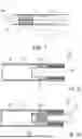


Sources:
- United States Patent and Trademark Office - verify current appl. status at the USPTO↗
Recent applications in this class:
- » 20260174151 2026-06-25
ATOMIZATION DEVICE - » 20260165386 2026-06-18
ATOMIZER AND AEROSOL GENERATING DEVICE - » 20260157444 2026-06-11
VAPORIZER AND ELECTRONIC VAPORIZATION DEVICE - » 20260144302 2026-05-28
SMOKING SUBSTITUTE APPARATUS - » 20260137128 2026-05-21
AEROSOL DELIVERY SYSTEMS AND METHODS - » 20260130434 2026-05-14
AEROSOL DELIVERY SUBSYSTEM - » 20260123685 2026-05-07
AEROSOL-GENERATING SYSTEM HAVING A CARTRIDGE AND A BYPASS AIR INLET - » 20260123684 2026-05-07
NON-COMBUSTIBLE AEROSOL PROVISION SYSTEMS WITH ATOMIZER-FREE CONSUMABLES - » 20260123683 2026-05-07
AEROSOL GENERATING DEVICE - » 20260114514 2026-04-30
ATOMIZER AND AEROSOL GENERATING DEVICE
Recent applications for this Assignee:
- » 20260174133 2026-06-25
ADJUSTABLE RETAINING MEMBER FOR AN AEROSOL-GENERATING DEVICE - » 20260174132 2026-06-25
AEROSOL-GENERATING DEVICE WITH TWO-PIECE INTERNAL HOUSING - » 20260174127 2026-06-25
AN AEROSOL-GENERATING ARTICLE HAVING A DOWNSTREAM TUBULAR ELEMENT - » 20260173229 2026-06-18
MICROWAVE HEATING UNIT AND METHOD - » 20260173220 2026-06-18
INDUCTION HEATING ARRANGEMENT FOR USE IN AN INDUCTIVELY HEATING AEROSOL-GENERATING DEVICE - » 20260165373 2026-06-18
CARTRIDGE WITH COMPACT INTERNAL ACTIVATION UNIT - » 20260165371 2026-06-18
AEROSOL-GENERATING DEVICE WITH A SENSING ASSEMBLY COMPRISING A SHIELDING PLATE - » 20260165363 2026-06-18
HUMIDITY ABSORBING WRAPPER FOR AEROSOL-GENERATING ARTICLE - » 20260157424 2026-06-11
PAPER WRAPPER FOR AN ELECTRICALLY HEATED AEROSOL-GENERATING ARTICLE - » 20260157422 2026-06-11
ADDITIVE APPLICATION WITHIN AEROSOL-GENERATING SEGMENT-CONVERGING DEVICE