BELT ASSEMBLY WITH REPOSITIONABLE STIFFENING ELEMENT
US20260174166A1
2026-06-25
19/426,652
2025-12-19
Smart Summary: A belt assembly has two layers that create a space in between. There is an opening in the top layer that lets you insert a stiffening element into this space. This stiffening element can be moved to different spots along the belt to provide support where needed. A special mechanism keeps the stiffening element in place but allows you to change its position easily. This design is great for carrying firearms and accessories comfortably while still being flexible for everyday use. 🚀 TL;DR
Abstract:
A belt assembly with a repositionable stiffening element includes a first layer and a second layer affixed to the first layer such that an interior cavity is formed between the layers. The second layer includes at least one opening providing access to the interior cavity. A stiffening element is insertable into the interior cavity via the opening and is positionable at any desired location along the length of the belt assembly. A retention mechanism maintains the stiffening element in position while allowing repositioning. The stiffening element provides rigidity in a selected portion of the belt assembly while allowing the remainder of the belt to remain flexible and conformable to a user's body. The belt assembly is particularly useful for concealed carry of firearms and accessories, providing comfort during all-day wear while supporting loads. The stiffening element can be easily repositioned to accommodate different carry positions and accessory placements.
Applicant:
Interested in similar patents?
Get notified when new applications in this technology area are published.
Classification:
A41F9/002 » CPC main
Belts, girdles, or waistbands for trousers or skirts Free belts
A45F5/021 » CPC further
Holders or carriers for hand articles; Holders or carriers for use while travelling or camping; Fastening articles to the garment to the belt
F41C33/041 » CPC further
Means for wearing or carrying smallarms; Holsters, i.e. cases for pistols having means for being carried or worn, e.g. at the belt or under the arm; Special attachments therefor for connecting a holster to a belt, webbing or other object
A41F9/00 IPC
Belts, girdles, or waistbands for trousers or skirts
A45F5/02 IPC
Holders or carriers for hand articles; Holders or carriers for use while travelling or camping Fastening articles to the garment
F41C33/04 IPC
Means for wearing or carrying smallarms; Holsters, i.e. cases for pistols having means for being carried or worn, e.g. at the belt or under the arm Special attachments therefor
Description
CROSS-REFERENCE TO RELATED APPLICATIONS
This application claims the benefit of U.S. Provisional Patent Application No. 63/737,241, filed Dec. 20, 2024 and titled “Belt Assembly with Repositionable Stiffening Element.” The entire contents of the above-identified priority application are hereby fully incorporated herein by reference.
TECHNICAL FIELD
This disclosure relates to a belt assembly with a repositionable stiffening element to provide rigidity in a selected portion of the belt assembly, particularly for supporting firearms and firearm accessories in concealed carry applications.
BACKGROUND
Traditional firearm belts are constructed to be thicker and rigid throughout the length of the belt to support the weight of a firearm or other firearm accessories. Traditional belts may have a metal or polymer core throughout the length of the belt and are typically used in combination with belt loops. Because of the thicker, rigid construction, traditional firearm belts are uncomfortable and fail to be able to conform to locations on the user other than the waist.
Several problems exist with traditional firearm belts. First, the uniform rigidity throughout the belt makes it uncomfortable for all-day wear, creating pressure points and restricting natural body movement. Second, the thick construction makes concealed carry under clothing difficult, as the belt creates visible bulges and printing of the firearm outline. Third, traditional belts cannot conform to different body positions (such as appendix, hip, or back carry) without causing discomfort. The rigid construction fights against natural body contours, leading to pinching, binding, and restricted mobility.
Fourth, once a belt is worn with belt loops, repositioning the firearm or accessories requires removing the belt entirely, removing the accessory, and reinstalling everything in the new position. This process is time-consuming and impractical for users who wish to adjust their carry position throughout the day. Fifth, the permanently rigid construction means the belt cannot be comfortably worn when not carrying a firearm, requiring users to own and switch between multiple belts for different purposes.
BRIEF SUMMARY
The present disclosure provides a belt assembly with a repositionable stiffening element that addresses the shortcomings of traditional firearm belts. The belt assembly comprises a first layer, a second layer affixed to the first layer such that an interior cavity is formed between the first and second layers, and at least one opening in the second layer providing access to the interior cavity. A stiffening element is insertable into the interior cavity via the opening and is positionable at any desired location along the length of the belt assembly. The stiffening element is retained within the interior cavity by a retention mechanism that prevents unwanted movement while allowing repositioning when desired.
The stiffening element provides rigidity in a selected portion of the belt assembly while allowing the remainder of the belt to remain flexible and conformable to the user's body. This selective rigidity enables comfortable all-day wear while providing adequate support for firearms and accessories weighing up to 5 pounds or more. The stiffening element can be easily repositioned within the interior cavity to accommodate different carry positions or relocated accessories, and can be removed entirely when not needed.
In various embodiments, the first layer comprises a material that grips or prevents movement relative to outer clothing, such as silicone, rubber, or similar materials with a coefficient of friction greater than 0.5. The second layer comprises a soft, breathable material positioned against the user's skin, such as neoprene or similar materials with moisture-wicking properties. The belt assembly includes a closure mechanism configured to secure opposing ends together, allowing adjustment of the belt length to fit different users with waist sizes ranging from approximately 28 inches to 54 inches.
The stiffening element may be constructed from various rigid materials including plastic, polyvinyl chloride, carbon fiber, metal, or combinations thereof, with a flexural modulus of at least 2 GPa. The length of the stiffening element may be customized to match the width of an accessory affixed to the belt assembly, or may extend the full length of the belt for maximum flexibility in accessory placement. In certain embodiments, the stiffening element has a thickness between 0.5 mm and 3 mm, a width between 1.25 inches and 2.25 inches, and a length between 4 inches and 36 inches.
In additional embodiments, the disclosure provides a stiffening element configured for insertion into a belt assembly, a kit comprising a belt assembly and multiple stiffening elements of different lengths, and methods for customizing belt rigidity and manufacturing belt assemblies with repositionable stiffening elements.
These and other aspects, objects, features, and advantages of the technology described herein will become apparent to those having ordinary skill in the art upon consideration of the following detailed description.
BRIEF DESCRIPTION OF THE DRAWINGS
An understanding of the features and advantages of the invention will be obtained by reference to the following detailed description that sets forth illustrative examples, in which the principles of the invention may be utilized, and the accompanying drawings of which:
FIG. 1 is a top perspective view of a belt assembly with an unengaged closure mechanism, in accordance with certain examples of the present disclosure.
FIG. 2 is a top perspective view of the belt assembly with an engaged closure mechanism, in accordance with certain examples of the present disclosure.
FIG. 3 is a top view of an outer layer of the belt assembly showing a first end of the belt assembly and a first portion of a closure mechanism, in accordance with certain examples of the present disclosure.
FIG. 4 is a top view of the outer layer of the belt assembly showing a second end of the belt assembly and included a second portion of the closure mechanism, in accordance with certain examples of the present disclosure.
FIG. 5 is a top perspective view of the belt assembly with an unengaged closure mechanism and a stiffening element, in accordance with certain examples of the present disclosure.
FIG. 6 is a side perspective view of the belt assembly with an engaged closure mechanism and a stiffening element, in accordance with certain examples of the present disclosure.
FIG. 7 is a top view of an inner layer of the belt assembly with a slit for insertion of a stiffening element, in accordance with certain examples of the present disclosure.
FIGS. 8A-8E illustrate sequential positioning of a stiffening element in a slit of an inner layer of the belt assembly, in accordance with certain examples of the present disclosure.
FIG. 9 is a side view depicting the belt assembly with an accessory affixed in a region of the belt assembly with the stiffening element, in accordance with certain examples of the present disclosure.
FIG. 10 is a side view depicting the belt assembly with an accessory affixed to the belt assembly, in accordance with certain examples of the present disclosure.
The figures herein are for illustrative purposes only and are not necessarily drawn to scale.
DETAILED DESCRIPTION
This disclosure provides a belt assembly with a repositionable stiffening element to provide rigidity in a selected portion of the belt assembly. The following detailed description provides a better understanding of the various aspects of the disclosure. References in the specification to “one embodiment,” “an embodiment,” “an example embodiment,” etc., indicate that the embodiment described may include a particular feature, structure, or characteristic, but every embodiment may not necessarily include the particular feature, structure, or characteristic. Additionally, such phrases are not necessarily referring to the same embodiment.
The innovations described herein can provide a firearm belt capable of supporting the weight of a firearm and other firearm accessories while remaining comfortable and conformable to various locations on a user. The belt can provide rigidity only where needed for supporting accessories, while maintaining flexibility elsewhere for comfort. Additionally, the belt can allow for easy repositioning of the support structure to accommodate different carry positions and accessory placements without requiring removal of the belt. The belt is also versatile enough for comfortable all-day wear regardless of whether accessories are attached.
Belt Assembly Overview
Referring now to FIGS. 1-10, various embodiments of a belt assembly with a repositionable stiffening element are illustrated. The belt assembly is designed to be worn by a user with or without the use of traditional belt loops. The belt assembly has an adjustable length via a closure mechanism and may be placed anywhere on the torso of a user. The belt is configured to accommodate users with waist sizes ranging from approximately 28 inches to 54 inches, though custom lengths outside this range can be manufactured.
In one embodiment, the belt assembly may be positioned underneath clothing of a user for concealed carry, reducing printing and visible outline of carried items by approximately 40-60% compared to traditional rigid belts. In another embodiment, the belt assembly may be positioned atop clothing of a user for open carry or tactical applications. The belt assembly can be worn at various positions including the waist, hips, or other torso locations, and is particularly suited for appendix carry, hip carry, and back carry positions.
The belt assembly is flexible and conformable to the positioned location on a user except in the location where the stiffening element is positioned. Testing has shown that non-stiffened portions of the belt exhibit approximately 300-500% greater flexibility than traditional firearm belts, allowing the belt to conform naturally to body contours. The stiffening element provides rigidity to support accessories that can be attached to the belt assembly, with load-bearing capacity of up to 5 pounds or more depending on the stiffening element material and dimensions selected.
In one embodiment, the stiffening element provides support for firearms and firearm accessories affixed to the belt assembly. The stiffening element can be positioned in a portion of the belt assembly where a holster or other firearm accessory is attached. The stiffening element can run the length of the belt assembly to allow easy repositioning of the holster or other firearm accessory at any point along the length of the belt assembly. The belt assembly is suitable for supporting compact pistols (typically 20-25 ounces), full-size pistols (typically 25-40 ounces), and associated accessories such as spare magazines (typically 3-8 ounces each).
Belt Structure and Dimensions
Referring to FIGS. 1 and 2, the belt assembly comprises an outer layer 110, an inner layer 120, and a closure mechanism 130. FIG. 1 depicts the belt assembly with the closure mechanism 130 in an unengaged state, while FIG. 2 shows the closure mechanism 130 in an engaged state, forming the belt into a substantially circular or oval shape suitable for wearing.
In typical embodiments, the belt assembly has a width between 1.5 inches and 2 inches, with 1.75 inches being a width that balances support capability with comfort and concealability. The overall length of the belt assembly when laid flat ranges from 30 inches to 60 inches depending on the intended user waist size, with common sizes being 36 inches (small), 42 inches (medium), 48 inches (large), and 54 inches (extra-large). The adjustable closure mechanism allows each size to accommodate a range of approximately 6-8 inches in waist circumference.
The outer layer 110 is configured to prevent movement of the belt assembly relative to outer layers of clothing worn by a user. In various embodiments, the outer layer 110 comprises a material that provides grip or traction against fabric, such as silicone, silicone rubber, rubber, synthetic rubber, latex, plastic, polymer, or vinyl. The outer layer 110 may have a coefficient of friction against common fabric materials (cotton, polyester, denim) of at least 0.5, and in certain examples between 0.7 and 1.2. This high friction prevents the belt from sliding or rotating during wear and movement.
In certain embodiments, the surface of the outer layer 110 may be textured, embossed, or patterned to enhance gripping properties. Surface textures may include raised dots, diamonds, lines, or other geometric patterns with feature heights between 0.1 mm and 2 mm. In some embodiments, the surface of the outer layer 110 may include lettering, logos, or any other type of ornamental design for branding or aesthetic purposes. The outer layer 110 typically has a thickness between 0.5 mm and 3 mm, with 1-2 mm being useful for balancing grip, durability, and low profile.
The inner layer 120 is configured to be positioned against a user's skin or against a base layer of clothing. In various embodiments, the inner layer 120 comprises a soft, breathable, moisture-wicking material to enhance comfort during extended wear. Suitable materials for the inner layer 120 include neoprene, elastane, Thermocline, Lexcell, or similar flexible, breathable fabrics. The material properties of the inner layer 120 are selected to prevent chafing, allow airflow, and wick moisture away from the skin.
The inner layer 120 may have a moisture vapor transmission rate of at least 1000 g/m2/24 hr to provide adequate breathability for all-day wear. The inner layer 120 typically has a thickness between 1 mm and 4 mm, with 2-3 mm being useful for comfort without excessive bulk. The inner layer 120 may have a Shore A hardness between 20 and 60, providing sufficient softness for comfort while maintaining structural integrity.
As illustrated in FIGS. 1-4, the inner layer 120 is affixed to the outer layer 110 such that an interior cavity is formed within the belt assembly. The interior cavity extends along substantially the entire length of the belt assembly between the two layers. The interior cavity has a height (thickness) between 0.5 mm and 4 mm, sized to snugly accommodate the stiffening element while allowing it to slide for repositioning. In certain embodiments, the cavity height is approximately 0.1 mm to 0.5 mm greater than the thickness of the stiffening element to provide a friction fit that retains the element in position while allowing intentional repositioning.
In various embodiments, the inner layer 120 is affixed to the outer layer 110 by stitching (e.g., hemming), adhesive bonding, thermal welding, RF welding, ultrasonic welding, or mechanical fasteners. In certain examples, the layers are joined using stitching around the perimeter edges with a stitch density of 8-12 stitches per inch, which provides durability while maintaining flexibility of the belt. The stitching may use nylon, polyester, or other synthetic thread with a breaking strength of at least 20 pounds.
In certain embodiments, as shown in FIGS. 1-4, the outer layer 110 is wider than the inner layer 120 by approximately 0.25 to 0.75 inches on each side. This dimensional difference allows the edges of the outer layer 110 to be folded over the edges of the inner layer 120 and secured, for example, with a hem stitch. This construction method provides a finished edge while securely bonding the two layers together and sealing the interior cavity along its perimeter, preventing debris from entering through the sides.
Closure Mechanism
The closure mechanism 130 is configured to secure opposing ends of the belt assembly together to form a closed loop around a user's body. As shown in FIGS. 1 and 2, the closure mechanism 130 allows for adjustment of the effective length of the belt assembly, enabling the belt to be customized in size for particular users or for positioning at different locations on the body. The closure mechanism 130 can provide at least 6 inches of length adjustability, and in certain examples 8-10 inches, to accommodate different body sizes and wearing preferences.
In various embodiments, the closure mechanism 130 may comprise a hook and loop fastener (e.g., Velcro), a buckle, a snap fastener, a clasp, a magnetic fastener, or combinations thereof. Hook and loop fasteners are particularly advantageous as they provide infinite adjustability within their engagement range and can be quickly fastened and unfastened. When using hook and loop fasteners, the hook portion can extend along 8-12 inches of one end of the belt, while the loop portion extends along a corresponding length on the opposite end or on the outer surface near the opposite end.
The closure mechanism 130 is securely attached to the opposing ends of the belt assembly using stitching, adhesive, or other suitable attachment methods. The attachment can withstand tensile forces of at least 50 pounds, and 75-100 pounds in certain examples, to prevent separation during normal wear and activities. In embodiments using buckles, the buckle may be a friction buckle, cam buckle, side-release buckle, or traditional frame buckle constructed from plastic or metal.
In certain embodiments, the closure mechanism 130 is positioned to avoid the region where the stiffening element 510 is typically positioned. This prevents interference between the rigid stiffening element and the closure mechanism. For example, if accessories are typically carried at the hip or back, the closure mechanism 130 may be positioned at the front of the belt where it will not overlap with the stiffened region.
Stiffening Element Structure and Materials
Referring to FIGS. 5-8E, the belt assembly further comprises a stiffening element 510 configured to provide rigidity in a selected portion of the belt assembly. The stiffening element 510 is insertable into the interior cavity of the belt assembly through one or more openings 710 in the inner layer 120. Once inserted, the stiffening element 510 may be positioned at any desired location within the interior cavity and along the length of the belt assembly.
The stiffening element 510 is constructed from a stiff, rigid, and substantially inflexible material to add rigidity to the belt assembly in the location where the stiffening element 510 is positioned. The stiffening element 510 may have a flexural modulus of at least 2 GPa, and in certain examples between 5 GPa and 200 GPa, depending on the material selected and the desired support characteristics. The stiffening element 510 should exhibit minimal deflection (less than 3 mm) when supporting a 3-pound load at its center with ends supported.
In various embodiments, suitable materials for the stiffening element 510 include plastic (such as acetal, polycarbonate, or high-density polyethylene), polyvinyl chloride (PVC), polystyrene, polyethylene, acrylonitrile butadiene styrene (ABS), polypropylene, carbon fiber composite, spring steel, stainless steel (including 301, 302, 304, or 316 stainless), aluminum alloy (including 6061 or 7075), titanium alloy, fiber-reinforced polymers (such as glass-fiber reinforced nylon), or any combination thereof. The material is selected based on desired stiffness, weight, durability, corrosion resistance, and comfort considerations.
In certain embodiments using polymer materials, the stiffening element 510 has a thickness between 0.8 mm and 2 mm, and between 1-1.5 mm in certain examples. When using metal materials such as spring steel or stainless steel, the stiffening element 510 may have a thickness between 0.3 mm and 1 mm, and between 0.4-0.6 mm in certain examples. Carbon fiber composite stiffening elements typically have a thickness between 0.5 mm and 2 mm depending on the number of layers and fiber orientation.
The width of the stiffening element 510 is selected to fit within the interior cavity between the outer layer 110 and inner layer 120. In certain embodiments, the width is between 1.25 inches and 2.25 inches, and may be 0.1 to 0.25 inches less than the width of the belt assembly to ensure the stiffening element 510 can be easily inserted and repositioned. For a belt with a 1.75-inch width, the stiffening element 510 may have a width between 1.5 and 1.65 inches.
The dimensions of the stiffening element 510 length can be varied depending on the application. In one embodiment, the length of the stiffening element 510 is substantially equal to the length of the belt assembly (e.g., 36-54 inches), allowing maximum flexibility in positioning accessories anywhere along the belt. In another embodiment, the length of the stiffening element 510 is less than the length of the belt assembly, being sized to correspond to a specific accessory width plus a margin for support. For example, the stiffening element 510 may have a length corresponding to the width of a holster plus 1-2 inches on each side for load distribution.
In various embodiments, common stiffening element lengths include: 4 inches (suitable for compact magazine carriers), 6 inches (suitable for single-stack compact pistol holsters), 8 inches (suitable for double-stack compact pistol holsters or most magazine carriers), 10 inches (suitable for full-size pistol holsters), 12 inches (suitable for large-frame pistol holsters or multiple accessories), and 14 inches or greater (suitable for extra-large firearms or multiple accessory configurations). The length may be any value in a range of 3 inches to 36 inches, with 6-14 inches being useful in certain concealed carry applications.
In certain embodiments, the length of the stiffening element 510 can be adjusted by a user. For example, the user may cut, trim, saw, or otherwise shorten the stiffening element 510 to a desired length to accommodate a specific accessory to be affixed to the belt assembly. Stiffening elements made from polymer materials can typically be cut with scissors, a utility knife, or a fine-tooth saw. Metal stiffening elements can be cut with metal shears, a hacksaw, or a rotary tool. The stiffening element 510 may include measurement markings along its length to guide the user in cutting to the desired size.
Stiffening Element Variations and Alternative Embodiments
Various alternative embodiments of the stiffening element 510 provide additional features and functionality. In one embodiment, the stiffening element 510 includes perforations or ventilation holes to reduce weight while maintaining rigidity. The perforations may be circular holes with diameters between 3 mm and 10 mm, spaced at regular intervals of 15-25 mm along the length and width of the element. This can reduce the weight by 20-40% while maintaining 70-85% of the original stiffness.
In another embodiment, the stiffening element 510 is pre-curved or contoured to match typical body contours. The element may have a gentle curve with a radius of curvature between 6 inches and 24 inches, corresponding to the natural curvature of the human torso at typical wearing positions. The pre-curved design improves comfort and concealment by eliminating gaps between the belt and body.
In yet another embodiment, the stiffening element 510 is telescoping or includes an adjustable length mechanism. For example, the element may comprise two or more segments that slide relative to each other and lock in place at selected positions, allowing adjustment from a compact length (e.g., 6 inches) to an extended length (e.g., 12 inches). The locking mechanism may comprise detents, friction locks, or pin-and-hole arrangements.
In still another embodiment, the stiffening element 510 comprises multiple layers of different materials bonded together. For example, a thin metal core (0.3-0.5 mm stainless steel) may be laminated between two polymer layers (0.5-0.8 mm each) to provide high stiffness with impact dampening and reduced noise. Alternatively, a carbon fiber layer may be combined with a polymer layer to improve the stiffness-to-weight ratio.
In a further embodiment, the stiffening element 510 includes integrated attachment points or mounting features for accessories. These may include holes, slots, or raised features positioned at standard spacing (e.g., 0.5-inch intervals) to allow direct attachment of holsters or accessory mounts without requiring belt clips. This provides a more secure and low-profile attachment method.
In another embodiment, the stiffening element 510 includes magnetic positioning features to aid in alignment with accessories. Small magnets (e.g., neodymium magnets 3-5 mm in diameter) may be embedded in or attached to the stiffening element at standard intervals. Corresponding magnets in the accessory or holster allow the user to quickly locate and position the stiffening element beneath the accessory location.
In yet another embodiment, the stiffening element 510 has a shaped or profiled cross-section rather than being uniformly flat. For example, the element may have a slight taper from center to edges, a convex or concave profile, or raised ribs for additional stiffness. These profiles can increase the effective stiffness by 20-50% compared to a flat element of the same thickness.
Retention Mechanism
One aspect of the belt assembly is the retention mechanism that maintains the stiffening element 510 in a desired position within the interior cavity while allowing intentional repositioning by the user. The retention mechanism prevents the stiffening element 510 from sliding or shifting during normal wear and movement, yet allows the user to reposition the element with reasonable manual force when desired.
In certain examples, retention is achieved through a friction fit between the stiffening element 510 and the interior surfaces of the outer layer 110 and inner layer 120. The interior cavity has a height (thickness between the layers) that is slightly greater than the thickness of the stiffening element 510, creating a snug fit. For example, the cavity height may be 0.1 mm to 0.5 mm greater than the stiffening element thickness. This dimensional relationship creates sufficient friction to prevent unintended movement while allowing repositioning with an applied force of approximately 2-5 pounds.
The friction fit is enhanced by the material properties of the inner layer 120 and/or outer layer 110. In certain embodiments, at least one of the layers comprises a high-friction material such as neoprene, rubber, or silicone that grips the stiffening element surfaces. The coefficient of friction between the stiffening element 510 and the interior cavity surfaces may be at least 0.3, and in certain examples between 0.4 and 0.8. This range provides adequate retention without making repositioning unduly difficult.
In alternative embodiments, the stiffening element 510 includes surface features that enhance retention. These features may include raised bumps or dimples on the major surfaces of the element, with feature heights between 0.1 mm and 0.5 mm. The features increase the surface area and mechanical interlocking with the interior cavity surfaces. The features may be arranged in regular patterns (e.g., grid of bumps spaced 5-10 mm apart) or may be randomly distributed.
In another embodiment, the stiffening element 510 includes textured surfaces created by processes such as knurling, bead blasting, or chemical etching. The textured surface increases the effective coefficient of friction and provides tactile feedback during insertion and positioning. Surface roughness (Ra) values between 1 and 10 micrometers are suitable for this purpose.
In still another embodiment, the retention mechanism comprises one or more retention tabs or flaps positioned at or near the opening 710. These tabs are formed from the inner layer 120 material or are separate components attached near the opening. The tabs partially overlap the path of the stiffening element 510, creating a light compressive force that must be overcome to insert or remove the element. The tabs may be positioned at the opening edges and extend inward by 3-10 mm, creating a spring-like retention force.
In a further embodiment, the opening 710 includes an elastic edge or band that grips the stiffening element 510 as it passes through. The elastic edge may be a separate elastic strip sewn or bonded around the perimeter of the opening, or may be formed by the natural elasticity of the inner layer 120 material. This creates a constriction that provides resistance during insertion and withdrawal while allowing passage of the element.
In yet another embodiment, the interior cavity includes internal ridges, ribs, or spacers that maintain the proper cavity height and create specific friction zones. These features may be formed by stitching lines that pass through both layers at intervals along the length of the belt, creating a series of channels or pockets. The stiffening element 510 slides through these channels, with the stitching lines providing retention points.
The retention force can be selected to prevent movement during activities such as walking, running, sitting, and bending, while allowing repositioning without tools and without requiring excessive force that could damage the belt. A retention force (force required to slide the element along the cavity) between 1 and 8 pounds, and in certain examples between 2 and 5 pounds, provides a balance for most users and applications.
Opening for Stiffening Element Insertion
Referring to FIGS. 7 and 8A-8E, the inner layer 120 includes at least one opening 710 that provides access to the interior cavity of the belt assembly. The opening 710 is sized and configured to allow insertion and removal of the stiffening element 510 while minimizing visible appearance and preventing debris entry during normal wear.
In one embodiment, the opening 710 is a slit cut or formed in the inner layer 120. The slit may be oriented longitudinally (parallel to the length of the belt), transversely (perpendicular to the length), or at an angle between 15 and 75 degrees from the longitudinal axis. A longitudinal slit facilitates easy insertion by allowing the stiffening element to slide directly along the belt length. The length of the slit can be between 1 and 4 inches, and in certain examples between 1.5 and 2.5 inches, providing adequate access while maintaining structural integrity of the inner layer 120.
In another embodiment, the opening 710 is formed by two pieces of inner layer 120 separated by a gap during assembly, with the pieces optionally overlapping to conceal the opening 710 when not in use. The overlap distance can be between 0.25 and 1 inch, creating a lap joint that hides the opening from view while allowing access by flexing or separating the overlapped portions. This configuration helps prevent the opening 710 from being visible during wear and prevents debris, moisture, or body oils from entering the interior cavity.
In various embodiments, the opening 710 may have a rectangular, oval, circular, or irregular shape. A rectangular opening with rounded corners allows easy insertion of the rectangular stiffening element while minimizing stress concentrations that could lead to tearing. The opening dimensions can be slightly larger than the stiffening element dimensions to facilitate insertion; for example, the opening width may be 0.1-0.2 inches greater than the stiffening element width.
The edges of the opening 710 can be reinforced to prevent fraying, tearing, or elongation over time with repeated insertions. Reinforcement may be achieved by edge binding with fabric tape, heat sealing, ultrasonic welding, or stitching around the perimeter of the opening. In embodiments using stitching, a bartack stitch or zigzag stitch at the corners of the opening provides additional reinforcement at these high-stress areas.
In one embodiment, the belt assembly includes a single opening 710 positioned at or near one end of the belt assembly, typically 1-4 inches from the end. This configuration allows the stiffening element 510 to be inserted and slid along the entire length of the interior cavity to any desired position. The opening can be positioned on the side of the belt that will be opposite the closure mechanism 130 when worn, placing it in a location that is easy to access.
In an alternative embodiment, the belt assembly includes a plurality of openings 710 distributed along the length of the belt assembly. Multiple openings provide increased flexibility in positioning the stiffening element 510 and allow for insertion of multiple stiffening elements at different locations. This is particularly useful when the user wishes to support multiple accessories (e.g., a holster and two magazine carriers) at different positions on the belt.
In embodiments with multiple openings, the openings may be evenly spaced along the length of the belt assembly at intervals of 6-12 inches, or may be positioned at specific locations corresponding to common accessory attachment points. For example, openings may be positioned at the 3 o'clock, 4 o'clock, 5 o'clock, 7 o'clock, and 8 o'clock positions relative to the body when the belt is worn (with 12 o'clock being the front center). These positions correspond to common carry locations for appendix carry, strong-side hip carry, and back carry.
Insertion and Positioning Process
FIGS. 8A-8E illustrate a sequential process for inserting the stiffening element 510 into the interior cavity of the belt assembly. This process demonstrates the ease of use and the ability to position the element at any desired location.
FIG. 8A shows the stiffening element 510 aligned with the opening 710 prior to insertion. The user positions the leading edge of the stiffening element at the opening, ensuring proper orientation (if the element has directional features). The stiffening element is typically inserted at approximately a 10-30 degree angle to the belt surface to facilitate entry into the cavity.
FIG. 8B depicts the initial insertion of the stiffening element 510 through the opening 710 and into the interior cavity. The user applies gentle pressure to slide the element into the cavity, with approximately 2-5 pounds of force typically required to overcome the friction fit. The element is guided along the interior cavity, with the cavity walls keeping it aligned and centered.
FIGS. 8C and 8D show progressive advancement of the stiffening element 510 further into the interior cavity. The user continues to push the element while simultaneously guiding it to the desired position. The element may be advanced along the entire length of the belt in 10-20 seconds with normal dexterity and strength. The friction fit provides resistance that prevents the element from sliding freely, giving the user positive control over the positioning.
FIG. 8E depicts the stiffening element 510 fully inserted into the interior cavity and positioned at the desired location. At this point, the user may make fine adjustments to the position by pushing or pulling the element through the opening or by manipulating the belt material to shift the element location. The retention mechanism holds the element in place once positioning is complete.
Once inserted, the stiffening element 510 can be positioned at any desired location along the length of the belt assembly by sliding it within the interior cavity. The total distance the element can be repositioned depends on the length of the belt and the length of the element. For a 42-inch belt with an 8-inch stiffening element, the element can be positioned anywhere along approximately 34 inches of belt length. The stiffening element 510 provides localized rigidity to the portion of the belt where it is positioned, while the remainder of the belt remains flexible. This selective rigidity allows the belt to conform comfortably to the user's body while providing adequate support for accessories.
The stiffening element 510 is removable from the interior cavity, allowing the user to remove it entirely for washing the belt assembly, for use when no accessories are attached, or for replacement with a different stiffening element having different properties (e.g., different length, material, or stiffness). The ability to remove and reinsert the stiffening element 510 also facilitates repositioning when the user wishes to change carry positions or relocate accessories. Removal is accomplished by grasping the element through the opening 710 and pulling it out with a force typically between 2 and 8 pounds.
In certain embodiments, two or more stiffening elements 510 may be inserted into the interior cavity of the belt assembly simultaneously. Multiple stiffening elements may be positioned at different locations to support multiple accessories (e.g., a holster at 4 o'clock and a magazine carrier at 8 o'clock), or may be stacked in a layered configuration at a single location to provide increased rigidity beyond that of a single stiffening element 510. Stacking multiple stiffening elements is particularly useful for supporting heavier firearms (e.g., full-size steel-frame pistols weighing 35-40 ounces) or when additional support is needed. Two stacked 1 mm stiffening elements typically provide 150-200% the rigidity of a single element, while two stacked 0.5 mm elements typically provide 120-150% the rigidity of a single 1 mm element.
Use with Accessories
FIGS. 9 and 10 illustrate the belt assembly with an accessory 910 attached, demonstrating the practical application and benefits of the repositionable stiffening element. As shown in FIG. 9, the accessory 910 is affixed to the belt assembly in the region where the stiffening element 510 is positioned within the interior cavity. The stiffening element 510 provides rigidity to support the weight of the accessory 910 and prevent sagging or shifting during wear.
The alignment between the stiffening element 510 and the accessory 910 allows optimal performance. Ideally, the stiffening element 510 is centered beneath the accessory with approximately 0.5-1.5 inches of stiffening element extending beyond each edge of the accessory. This ensures that the entire footprint of the accessory is supported by rigid belt material. The user can feel the location of the stiffening element 510 through the belt material and position it appropriately before attaching the accessory.
In various embodiments, the accessory 910 may be a firearm holster (inside-the-waistband or outside-the-waistband), a magazine carrier (single or double stack), a knife sheath, a multitool holder, a flashlight holder, a tourniquet holder, a medical equipment pouch, a handcuff case, a spare ammunition pouch, or any other accessory intended to be carried on a belt. The total weight of typical accessories ranges from 4 ounces for an empty magazine carrier to 40-50 ounces for a loaded full-size pistol in a holster. The belt assembly and stiffening element are designed to comfortably support loads in this range.
The accessory 910 may be attached to the belt assembly using various attachment mechanisms. Common mechanisms include: belt clips that clamp over the belt edge, belt loops that the belt threads through, hook and loop fastener strips that engage with the belt surface, snap fasteners, paddle attachments that hook over the belt and wedge against the body, and dedicated mounting plates or adapters. The attachment mechanism engages with either the outer layer 110 or the inner layer 120 of the belt assembly, or may span both layers.
In certain embodiments, accessories attach to the outer layer 110 so that the grippy surface helps prevent rotation or shifting of the accessory. Belt clips or loops that grip the belt with a clamping force of at least 10 pounds, and in certain examples between 15-25 pounds, provide secure attachment that resists movement even during vigorous activity such as running or drawing a firearm. The combination of the high-friction outer layer 110 and the localized rigidity from the stiffening element 510 creates a stable platform for accessory attachment.
The ability to reposition the stiffening element 510 allows the user to optimize support based on the specific accessory being carried and the desired carry position. For example, when carrying a firearm in an appendix position (front center or slightly offset), the stiffening element 510 can be positioned at the front of the belt, typically in the 12 o'clock to 2 o'clock position. When carrying in a hip position (strong-side), the stiffening element 510 can be positioned at the 3 o'clock to 4 o'clock position for a right-handed user or 8 o'clock to 9 o'clock position for a left-handed user. For back carry, the element is positioned at the 6 o'clock position.
This flexibility eliminates the need for multiple specialized belts for different carry positions. A single belt assembly can be adapted for various uses simply by repositioning the stiffening element 510. This is particularly advantageous for users who change carry positions based on clothing, activity, or situation, or who wish to experiment with different positions to find what works best for them.
Furthermore, if the user switches to a different firearm or holster with different dimensions, the stiffening element 510 can be removed and replaced with one of a different length to match the new accessory width. This modularity extends the useful life of the belt assembly and provides flexibility as the user's needs evolve.
Performance Characteristics and Advantages
The belt assembly of the present disclosure provides numerous advantages over traditional firearm belts, with measurable performance improvements in several key areas.
Flexibility and Comfort: The selective rigidity provided by the repositionable stiffening element allows the belt to be comfortable for all-day wear while still providing adequate support for firearms and accessories. Testing has demonstrated that non-stiffened portions of the belt exhibit approximately 300-500% greater flexibility compared to traditional rigid firearm belts. This increased flexibility translates to reduced pressure points, with users reporting 40-60% reduction in discomfort during extended wear periods exceeding 8 hours. The flexible portions of the belt conform naturally to the user's body, reducing hot spots and allowing natural movement during activities such as sitting, bending, and reaching.
Load-Bearing Capacity: Despite the selective rigidity approach, the stiffened region of the belt provides adequate support for typical concealed carry loads. Testing has shown that an 8-inch stiffening element made from 1 mm polycarbonate can support a center-loaded weight of 5 pounds with less than 5 mm of deflection. A 10-inch carbon fiber stiffening element (1.5 mm thick) can support up to 8 pounds with similar deflection. These load capacities exceed the requirements for most concealed carry applications, where the total system weight (firearm, holster, ammunition, and accessories) typically ranges from 1.5 to 3.5 pounds.
Concealment Improvement: The low-profile design and selective stiffening significantly improve concealment compared to traditional rigid belts. The flexible, conforming nature of the non-stiffened regions eliminates the rigid arc that traditional belts create when worn under clothing. User studies have shown an approximately 40-60% reduction in visible printing (outline of the firearm showing through clothing) compared to traditional ¼-inch thick rigid leather or reinforced nylon belts. The reduction in belt thickness from typically 6-8 mm for traditional belts to 3-5 mm for the present belt assembly further improves concealment, especially when wearing fitted clothing.
Versatility: The belt can be worn without traditional belt loops, allowing for positioning at various locations on the torso beyond just the waist. This enables unconventional carry positions such as high appendix carry, cross-draw positions, and shoulder-to-hip positions. The grippy outer layer 110 prevents the belt from sliding down or rotating even without belt loops. This configuration provides options for users who prefer looser-fitting clothing without belt loops, such as athletic wear, or for use in situations where belt loops would be visible and undesirable.
Repositioning Convenience: Unlike traditional rigid belts that must be removed to change accessory positions, the present belt assembly allows repositioning of the support structure while the belt remains worn. A user can unclip the accessory, reposition the stiffening element 510 within approximately 10-30 seconds, and reattach the accessory in the new location. This is particularly valuable for users who need to adjust carry position due to changing activities (e.g., driving vs. walking), changing between multiple firearms of different sizes, or accommodating different clothing styles.
Washability and Maintenance: The removable stiffening element 510 allows for easy cleaning of the belt assembly. The user can remove the element and wash the belt according to the care instructions for the materials used (typically hand wash or gentle machine wash for neoprene/nylon constructions). This is a significant advantage over traditional rigid belts with permanently embedded stiffeners, which cannot be thoroughly cleaned and may retain moisture, sweat, and odors. The ability to remove the stiffening element also allows for drying the belt more quickly and thoroughly, extending its useful life.
Modularity and Adaptability: The system provides exceptional modularity and adaptability to changing needs. Users can maintain a collection of stiffening elements of different lengths (e.g., 6-inch, 8-inch, 10-inch, and 12-inch) and select the appropriate one for each situation. A user carrying a compact pistol might use a 6-inch element, while the same user carrying a full-size pistol and spare magazines might use a 12-inch element or multiple shorter elements. The initial investment in the belt assembly and a set of stiffening elements is comparable to purchasing a single traditional rigid belt, yet provides far greater versatility.
Manufacturing Methods
The belt assembly can be manufactured using various methods and production techniques. The following describes example manufacturing processes that produce high-quality belt assemblies with consistent performance characteristics.
Layer Material Preparation: The outer layer 110 can be cut or die-cut from sheet material such as silicone rubber, PVC, or similar grippy material in the desired length and width dimensions. For a typical belt, the outer layer is cut to a length of 36-54 inches and a width of 2-2.5 inches. The inner layer 120 is cut from neoprene, elastane, or similar soft, breathable material to a length matching the outer layer and a width that is 0.25-0.75 inches less than the outer layer width. This dimensional difference allows for edge folding and hemming.
Opening Formation: The opening 710 in the inner layer 120 is formed before assembly of the layers. The opening may be created by laser cutting, die cutting, rotary cutting, or hot knife cutting, depending on the material and production volume. Laser cutting is useful for synthetic materials as it simultaneously cuts and seals the edges, preventing fraying. The opening is typically formed 2-4 inches from one end of the inner layer. If multiple openings are desired, they are formed at the appropriate intervals during this step.
Edge Reinforcement: The edges of the opening 710 can be reinforced to enhance durability. Reinforcement may be accomplished by edge binding with fabric tape, heat sealing to melt and fuse the material edges, or stitching around the perimeter with a bartack or zigzag stitch. Heat sealing is particularly suitable for synthetic materials and can be performed simultaneously with the cutting operation using a heated cutting tool. Edge binding provides the most durability but requires additional material and processing time.
Layer Joining: The inner layer 120 is positioned atop the outer layer 110 with edges aligned or with the inner layer centered to leave equal margins of outer layer material on each side. The layers are then joined along their perimeter edges. In certain embodiments, the edges of the outer layer 110 are folded over the edges of the inner layer 120, and the folded edges are stitched down using a lockstitch, chainstitch, or coverstitch. A stitch density of 8-12 stitches per inch provides adequate strength and durability. Heavy-duty thread such as nylon or polyester bonded thread with a tex size of 70-135 is suitable for this application.
Alternative joining methods include: adhesive bonding using pressure-sensitive adhesives, contact adhesives, or hot-melt adhesives applied to the layer interfaces; thermal welding using heat and pressure to fuse thermoplastic materials together; RF (radio frequency) welding for materials such as PVC that respond to RF energy; ultrasonic welding using high-frequency vibration to create a molecular bond; or combinations of these methods. Stitching is generally useful as it provides excellent strength, is visually apparent for quality control, and allows for easy repair if needed.
Quality Control: Assembled belts are inspected for proper cavity height, opening integrity, stitch quality, and overall construction. The interior cavity height is measured at several points along the length to ensure consistency within +/−0.2 mm of the target dimension. A sample stiffening element is inserted to verify smooth insertion and proper retention force. The retention force is measured by pulling the inserted element with a force gauge; acceptable retention force is typically 2-5 pounds. Belts that do not meet specifications are rejected or reworked as appropriate.
Closure Mechanism Attachment: The selected closure mechanism 130 is attached to the opposing ends of the assembled belt. For hook and loop fasteners, the hook portion is sewn or adhesively bonded to one end of the belt (typically the outer surface), while the loop portion is attached to the other end (outer surface or inner surface depending on the overlap configuration desired). In certain examples, the attachment can withstand a pull force of at least 50 pounds, and in some examples 75-100 pounds. For buckles, the buckle is secured to one end and the belt is threaded through or attached according to the buckle design.
Stiffening Element Manufacturing: The stiffening elements 510 are manufactured separately from the belt assembly. For polymer materials, stiffening elements can be cut from sheet stock using shears, die cutting, laser cutting, or CNC routing. For metal materials, elements are cut using metal shears, water jet cutting, laser cutting, or stamping. The cut edges are deburred or chamfered to remove sharp edges that could snag on the interior cavity or cause discomfort. Elements may be surface treated (such as bead blasting, knurling, or coating) to modify friction properties or appearance. Optional measurement markings may be printed or engraved along the length.
Packaging: The belt assembly and one or more stiffening elements are packaged together for sale. A typical retail package includes the belt assembly, one stiffening element of a standard length (e.g., 8 inches or 10 inches), and an instruction sheet with diagrams showing insertion and positioning procedures. Deluxe packages may include multiple stiffening elements of different lengths (e.g., 6-inch, 8-inch, and 10-inch) to provide maximum versatility. The packaging clearly identifies the belt size, color, and included components.
Belt Assembly Variations
In addition to the variations of the stiffening element previously described, the belt assembly itself may include various alternative embodiments and features that enhance functionality, comfort, or convenience.
In one embodiment, the belt assembly includes multiple openings 710 positioned at strategic locations corresponding to common carry positions. For example, openings may be positioned at 3-4 inches, 12-14 inches, and 20-22 inches from one end of the belt. These positions allow the user to quickly insert stiffening elements at standard locations without having to slide them long distances through the interior cavity. The multiple openings also facilitate the use of multiple stiffening elements to support multiple accessories simultaneously.
In another embodiment, the edges of the belt around the opening 710 are reinforced with additional material layers or structural elements. The reinforcement may extend 1-2 inches in all directions from the opening and provides increased resistance to tearing and wear at this high-stress area. The reinforcement may be formed by additional layers of fabric bonded or stitched in place, plastic or metal grommets installed around the opening perimeter, or localized heat treatment to increase material density and strength.
In yet another embodiment, the closure mechanism 130 is strategically positioned to avoid the typical location of the stiffening element 510. For example, if the stiffening element is typically positioned at the hip or back (3-8 o'clock positions), the closure mechanism may be positioned at the front of the belt (11-1 o'clock positions). This prevents any interaction or interference between the rigid stiffening element and the closure mechanism, and ensures that the closure mechanism can engage and disengage smoothly without being affected by the stiffening element.
In still another embodiment, the belt assembly includes integrated pouches or pockets formed within the interior cavity. These pouches are separate from the main cavity that receives the stiffening element and are accessed through separate openings. The pouches can be used to store small items such as spare keys, cash, medication, or backup accessories. The pouches can be positioned in areas where the stiffening element is not typically located, such as at the back center of the belt or near the closure mechanism.
In a further embodiment, the belt assembly includes visual alignment marks or indicators on the outer or inner surface to assist the user in positioning the stiffening element. The marks may be printed, embossed, or sewn onto the belt at regular intervals (e.g., every 2 inches) and may include measurement scales or position indicators (e.g., 3:00, 4:00, 5:00 clock positions). The user can align the stiffening element with these marks to quickly position it at the desired location.
In yet another embodiment, the belt assembly incorporates elastic sections at one or more locations to improve flexibility and comfort while maintaining adequate support when the stiffening element is in place. The elastic sections may be formed by using elastic material for portions of the inner layer 120, or by incorporating separate elastic panels between the layers. Elastic sections of 2-4 inches in length positioned at the sides of the belt (9 o'clock and 3 o'clock positions) can significantly improve comfort when sitting or bending without compromising support in the stiffened region.
In still another embodiment, the inner layer 120 includes perforations or ventilation channels to enhance breathability and reduce heat buildup against the skin. The perforations may be small holes (1-3 mm diameter) arranged in patterns, or may be formed by using a perforated or mesh material for portions of the inner layer. Enhanced breathability is particularly beneficial in warm climates or during physical activity, reducing perspiration and improving comfort during extended wear.
Additional Functional Details
Several additional functional aspects of the belt assembly enhance its practical utility and address user needs in various situations.
Compatibility with Traditional Belt Loops: The belt assembly is compatible with standard belt loops found on pants, shorts, and other garments. The belt can be threaded through belt loops in the conventional manner if desired, providing additional security and positioning stability. However, unlike traditional belts that require belt loops for proper function, the present belt assembly can be worn effectively without belt loops due to the high-friction outer layer 110 that grips the clothing. This dual capability provides users with flexibility to wear the belt with or without belt loops depending on their clothing and preferences.
Over-Clothing and Under-Clothing Wear: The belt assembly is specifically designed to be worn either over clothing or under clothing. When worn over clothing (outside the waistband), the grippy outer layer 110 prevents the belt from sliding down or rotating relative to the outer garment. When worn under clothing (inside the waistband or against the skin), the soft, breathable inner layer 120 provides comfort and prevents chafing even during all-day wear and physical activity. The low-profile design ensures that the belt does not create excessive bulk or visible lines under clothing in either configuration.
Washability and Care: The belt assembly is designed for easy maintenance and cleaning. Users are instructed to remove the stiffening element 510 before washing the belt. Once the element is removed, the belt can be hand washed in cold or warm water with mild detergent, or machine washed on a gentle cycle. The removal of the rigid stiffening element prevents damage to the washing machine and allows the belt to flex and move freely during washing, ensuring thorough cleaning. After washing, the belt is air dried or tumble dried on low heat. The stiffening element can be wiped clean with a damp cloth if needed.
Durability and Opening Edge Integrity: The edges of the opening 710 are subject to repeated stress during insertion and removal of the stiffening element. The reinforcement methods previously described (edge binding, heat sealing, or stitching) significantly enhance the durability of the opening. Testing has demonstrated that properly reinforced openings can withstand at least 500 insertion/removal cycles without significant wear or tearing. For most users who reposition the stiffening element a few times per week, this translates to several years of service life. If edge wear does occur, the opening can be easily repaired by applying additional stitching or edge binding.
Stiffening Element Insertion Orientation: In most embodiments where the stiffening element 510 is symmetrical, the orientation during insertion is not critical. However, in embodiments where the element has directional features (such as a tapered profile, asymmetric curve, or directional texture), proper orientation is important. The stiffening element may be marked with orientation indicators (e.g., arrows or labels indicating ‘Top’ or ‘Front’) to guide the user. Alternatively, the element may be shaped asymmetrically so that it can only be inserted in the correct orientation.
Multi-Purpose Use: While the belt assembly is particularly well-suited for concealed carry of firearms and accessories, it is equally useful for other applications requiring selective rigidity and support. For example, the belt can be used to carry tools and equipment for professional tradespeople, outdoor and camping gear, photography equipment, medical supplies for first responders, or any other items that benefit from rigid support in specific locations while maintaining overall belt flexibility and comfort.
Belt Assemblies and Methods of Manufacture
Belt Assembly Structure
In accordance with the present disclosure, a belt assembly is provided comprising a first layer and a second layer. The first layer and second layer are affixed to each other such that an interior cavity is formed between the first and second layers. The interior cavity extends along substantially the entire length of the belt assembly.
In certain embodiments, the first layer comprises an outer layer and the second layer comprises an inner layer, wherein the inner layer corresponds to a side of the belt assembly facing a user wearing the belt assembly. The outer layer is configured to face outward toward the user's clothing or environment, while the inner layer is configured to face inward toward the user's body.
The second layer comprises at least one opening to the interior cavity. The opening provides access to the interior cavity for insertion and removal of components. In some embodiments, the at least one opening comprises a slit in the second layer. In other embodiments, the second layer comprises a plurality of openings distributed along a length of the belt assembly.
Stiffening Element
A stiffening element is provided that is insertable into the interior cavity via the at least one opening. Once inserted, the stiffening element is positionable within the interior cavity of the belt assembly, meaning it can be moved to different locations along the length of the belt assembly. The stiffening element is also removable from the interior cavity of the belt assembly, allowing the user to take it out entirely when desired.
The stiffening element is configured to add rigidity to the belt assembly along a length of the stiffening element. This means that the portion of the belt assembly where the stiffening element is positioned becomes more rigid and less flexible, while other portions of the belt assembly without the stiffening element remain flexible.
Stiffening Element Dimensions
The length of the stiffening element may correspond to various dimensions depending on the intended use. The length may correspond to: a length of the belt assembly (full-length element); a length less than the length of the belt assembly (partial-length element); a length of a portion of the belt assembly corresponding to a width of an accessory affixed to the belt assembly; specific lengths including 4 inches, 6 inches, 8 inches, 10 inches, or 12 inches; a length in a range of 3 inches to 36 inches; a length in a range of 3 inches to 24 inches; a length in a range of 3 inches to 12 inches; or a length in a range of 6 inches to 14 inches.
The stiffening element has a thickness between 0.3 mm and 3 mm. The interior cavity has a height between 0.5 mm and 4 mm, which accommodates the thickness of the stiffening element while allowing it to slide within the cavity.
The stiffening element has a width between 1.25 inches and 2.25 inches, which is sized to fit within the interior cavity of the belt assembly.
Stiffening Element as Separate Component
In certain embodiments, a stiffening element for insertion into a belt assembly is provided as a separate component. This stiffening element comprises a substantially rigid planar body having: a length between 3 inches and 36 inches; a width between 1.25 inches and 2.25 inches; and a thickness between 0.3 mm and 3 mm. The stiffening element is configured to fit within an interior cavity of a belt assembly and provide rigidity along its length.
Stiffening Element Materials and Properties
The stiffening element comprises one or more materials selected from the group consisting of: plastic, polyvinyl chloride, polystyrene, polyethylene, acrylonitrile butadiene styrene, polypropylene, carbon fiber, spring steel, stainless steel, aluminum, and titanium. In particular embodiments, the substantially rigid planar body comprises a material selected from: polycarbonate, carbon fiber composite, stainless steel, aluminum, and combinations thereof.
The stiffening element has a flexural modulus of at least 2 GPa. In certain embodiments, the substantially rigid planar body has a flexural modulus between 5 GPa and 200 GPa, providing the necessary rigidity to support accessories attached to the belt assembly.
Stiffening Element Features
In some embodiments, the stiffening element includes perforations for weight reduction while maintaining rigidity. These perforations reduce the overall weight of the stiffening element without significantly compromising its structural rigidity.
In certain embodiments, the stiffening element is pre-curved to match body contours. The substantially rigid planar body may be pre-curved with a radius of curvature between 6 inches and 24 inches, allowing it to conform more naturally to the user's body shape.
The stiffening element may include surface features configured to increase friction with interior surfaces of the interior cavity. These surface features help retain the stiffening element in position within the cavity.
In some embodiments, the length is user-adjustable by cutting or trimming, allowing users to customize the stiffening element length for their specific needs. The stiffening element may further comprise measurement markings along the length to guide user trimming.
In certain embodiments, the substantially rigid planar body comprises multiple material layers bonded together, providing a combination of properties such as rigidity and impact resistance.
Plurality of Stiffening Elements
The belt assembly may further comprise a plurality of stiffening elements, wherein each of the plurality of stiffening elements is configured to insert into the interior cavity via the at least one opening. In some embodiments, the plurality of stiffening elements are disposed within the interior cavity in a stacked configuration, where two or more elements are layered on top of each other to provide increased rigidity.
Retention Mechanism
The belt assembly may further comprise a retention mechanism configured to retain the stiffening element in a desired position within the interior cavity while allowing repositioning of the stiffening element by a user.
In certain embodiments, the retention mechanism comprises a friction fit between the stiffening element and interior surfaces of the interior cavity. This friction fit prevents unwanted movement of the stiffening element during normal use, but allows the user to intentionally reposition it by applying sufficient force.
In other embodiments, the retention mechanism comprises surface features on the stiffening element that engage with the interior surfaces of the interior cavity, providing mechanical interlocking or increased friction.
Layer Materials and Properties
First Layer (Outer Layer)
The first layer comprises one or more materials selected from the group consisting of: silicone, silicone rubber, rubber, synthetic rubber, latex, plastic, polymer, and vinyl. These materials provide grip and prevent movement of the belt assembly relative to the user's clothing.
In certain embodiments, the first layer has a coefficient of friction against fabric materials of at least 0.5. This high coefficient of friction ensures that the belt assembly remains in position during wear and does not slide or rotate.
Second Layer (Inner Layer)
The second layer comprises one or more materials selected from the group consisting of: neoprene, elastane, Thermocline, and Lexcell. These materials provide comfort, breathability, and moisture-wicking properties when the belt assembly is worn against the user's skin or over a base layer.
Affixing Layers
The first layer is affixed to the second layer by one or more of stitching, adhesive, welding, or mechanical fasteners positioned at outer surfaces of the first layer and the second layer such that the interior cavity is formed. This affixing method securely bonds the two layers together while creating and maintaining the interior cavity space.
Closure Mechanism
The belt assembly further comprises a closure mechanism configured to secure opposing ends of the belt assembly together. The closure mechanism allows the belt assembly to be formed into a closed loop around the user's body.
In various embodiments, the closure mechanism comprises one or more mechanisms selected from the group consisting of: a hook and loop fastener, a buckle, a snap fastener, a clasp, and a magnetic fastener. These closure mechanisms provide secure attachment while allowing adjustment of the belt length.
Use with Accessories
The belt assembly is configured to support an accessory along the length of the stiffening element. The rigidity provided by the stiffening element allows the belt to bear the weight of the accessory without sagging or deforming.
In certain embodiments, the accessory comprises one or more of a firearm holster or a magazine carrier. Other accessories may include knife sheaths, tool holders, or equipment pouches.
Belt Assembly Wearing Configurations
The belt assembly is configured to be worn without belt loops, meaning that the grippy outer layer provides sufficient friction to hold the belt in place on the user's body or over clothing without requiring traditional belt loops.
The belt assembly is configured to support a load of at least 3 pounds at the selected position where the stiffening element is disposed. This load-bearing capacity accommodates typical firearms and accessories.
Repositionable Stiffening Element
In certain embodiments, a belt assembly is provided comprising a repositionable stiffening element disposed within the interior cavity and configured to provide selective rigidity to the belt assembly at a selected position along a length of the belt assembly.
The stiffening element is slidable along the interior cavity to different positions, allowing the user to move the area of rigidity to wherever accessories are to be attached.
Portions of the belt assembly not containing the stiffening element exhibit at least 300% greater flexibility than the portion containing the stiffening element. This selective rigidity provides support where needed while maintaining flexibility and comfort elsewhere.
Kit Configuration
In some embodiments, a kit is provided comprising: a belt assembly comprising a first layer and a second layer affixed to the first layer to form an interior cavity, the second layer comprising at least one opening; and a plurality of stiffening elements of different lengths, wherein each stiffening element is insertable into the interior cavity via the at least one opening.
In certain embodiments, the plurality of stiffening elements includes at least three stiffening elements having lengths of 6 inches, 8 inches, and 10 inches, providing users with options for different accessory sizes.
The kit may further comprise instructions for inserting and positioning the stiffening elements within the interior cavity.
In some embodiments, the plurality of stiffening elements are constructed from different materials to provide different rigidity characteristics, allowing users to select the appropriate stiffness for their specific needs.
In certain embodiments, at least one of the stiffening elements includes perforations and at least one of the stiffening elements is solid, providing options for weight-reduced and maximum-rigidity configurations.
Method of Adding Rigidity
A method of adding rigidity to a belt assembly is provided, the method comprising: providing a belt assembly comprising a first layer and a second layer affixed to the first layer such that an interior cavity is formed, the second layer comprising at least one opening; inserting a stiffening element through the at least one opening and into the interior cavity of the belt assembly; and positioning the stiffening element within the interior cavity, wherein the stiffening element adds rigidity to the belt assembly along a length of the stiffening element within the interior cavity.
The method may further comprise attaching an accessory to the belt assembly at a location corresponding to a position of the stiffening element within the interior cavity, ensuring that the accessory is supported by the rigid portion of the belt.
The method may further comprise repositioning the stiffening element to a different location within the interior cavity, allowing the user to change where support is provided without removing the belt.
The method may further comprise removing the stiffening element from the interior cavity, such as for washing the belt or when no accessories are to be carried.
The method may further comprise inserting a plurality of stiffening elements into the interior cavity via the at least one opening, allowing support at multiple locations simultaneously. The plurality of stiffening elements may be positioned in a stacked configuration within the interior cavity for increased rigidity.
In certain embodiments, inserting the stiffening element comprises sliding the stiffening element through the at least one opening and advancing the stiffening element along a length of the interior cavity to a desired position.
The method may further comprise adjusting a length of the stiffening element prior to inserting the stiffening element into the interior cavity, such as by cutting or trimming to match a specific accessory width.
The method may further comprise wearing the belt assembly at a torso location without use of belt loops, relying on the grippy outer layer to maintain position.
The method may further comprise selecting a length of the stiffening element based on a width of an accessory to be attached to the belt assembly, optimizing support for the specific accessory.
In certain embodiments, positioning the stiffening element comprises aligning the stiffening element with visual alignment marks on the belt assembly, facilitating accurate placement.
The method may further comprise a repositioning workflow including: removing the accessory from the belt assembly; repositioning the stiffening element to a new location within the interior cavity; and reattaching the accessory at the new location.
ALTERNATIVE EMBODIMENTS AND MODIFICATIONS
The example systems, methods, and components described in the embodiments presented previously are illustrative, and, in alternative embodiments, certain components can be combined in a different order, omitted entirely, and/or combined between different example embodiments, and/or certain additional components can be added, without departing from the scope and spirit of various embodiments.
In some embodiments, the stiffening element may be curved or pre-shaped to match typical body contours at common wearing positions. For example, a stiffening element intended for appendix carry may have a gentle convex curve to follow the natural contour of the lower abdomen, while an element for hip carry may have a different curve to match the hip contour. The pre-shaped elements improve comfort and concealment by eliminating gaps between the belt and body. The curvature may be permanent (formed during manufacturing) or may be created by materials with shape memory properties that allow the user to form the desired curve.
In other embodiments, the stiffening element may be constructed from materials with shape memory or superelastic properties such as nitinol (nickel-titanium alloy). These materials can be flexed or bent for easy insertion through the opening, and then return to their designed shape once positioned in the interior cavity. This allows the use of longer stiffening elements (e.g., 18-24 inches) that would otherwise be difficult to insert through a small opening.
In yet other embodiments, the belt assembly may include features such as integrated D-rings, attachment loops, or MOLLE (Modular Lightweight Load-carrying Equipment) webbing for attaching additional pouches or equipment. These features expand the versatility of the belt beyond concealed carry applications to include tactical, outdoor, and professional use cases.
In still other embodiments, the belt assembly may incorporate multiple interior cavities separated by internal partitions or dividers. Different cavities could accommodate stiffening elements of different widths or could serve different purposes (e.g., one cavity for the stiffening element and a separate cavity for storage). The multiple cavities would be accessed through separate openings positioned at appropriate locations.
In further embodiments, the stiffening element itself may include features beyond simple structural support. For example, the stiffening element could incorporate embedded electronics such as RFID chips for tracking or identification, LED lights for visibility in low-light conditions, heating elements for cold-weather comfort, or sensors for monitoring physiological parameters or environmental conditions.
Although specific embodiments have been described above in detail, the description is merely for purposes of illustration. It should be appreciated, therefore, that many aspects described above are not intended as required or essential elements unless explicitly stated otherwise. Modifications of, and equivalent components or acts corresponding to, the disclosed aspects of the example embodiments, in addition to those described above, can be made by a person of ordinary skill in the art, having the benefit of the present disclosure, without departing from the spirit and scope of the invention defined in the following claims, the scope of which is to be accorded the broadest interpretation so as to encompass such modifications and equivalent structures.
Claims
What is claimed is:1. A belt assembly, comprising:
a first layer;
a second layer affixed to the first layer such that an interior cavity is formed between the first and second layers, the second layer comprising at least one opening to the interior cavity; and
a stiffening element that is insertable into the interior cavity via the at least one opening.
2. The belt assembly of claim 1, wherein the first layer comprises an outer layer and the second layer comprises an inner layer, the inner layer corresponding to a side of the belt assembly facing a user wearing the belt assembly.
3. The belt assembly of claim 1, wherein the stiffening element is positionable within the interior cavity of the belt assembly.
4. The belt assembly of claim 1, wherein the stiffening element is removable from the interior cavity of the belt assembly.
5. The belt assembly of claim 1, wherein the stiffening element is configured to add rigidity to the belt assembly along a length of the stiffening element.
6. The belt assembly of claim 5, wherein the belt assembly is configured to support an accessory along the length of the stiffening element.
7. The belt assembly of claim 6, wherein the accessory comprises one or more of a firearm holster or a magazine carrier.
8. The belt assembly of claim 1, further comprising a plurality of stiffening elements, each of the plurality of stiffening elements configured to insert into the interior cavity via the at least one opening.
9. The belt assembly of claim 8, wherein the plurality of stiffening elements are disposed within the interior cavity in a stacked configuration.
10. The belt assembly of claim 1, wherein the first layer is affixed to the second layer by one or more of stitching, adhesive, welding, or mechanical fasteners positioned at outer surfaces of the first layer and the second layer such that the interior cavity is formed.
11. The belt assembly of claim 1, further comprising a closure mechanism configured to secure opposing ends of the belt assembly together.
12. The belt assembly of claim 11, wherein the closure mechanism comprises one or more mechanisms selected from the group consisting of: a hook and loop fastener, a buckle, a snap fastener, a clasp, and a magnetic fastener.
13. The belt assembly of claim 1, wherein the second layer comprises a plurality of openings distributed along a length of the belt assembly.
14. The belt assembly of claim 13, wherein one or more stiffening elements are inserted into the interior cavity via one or more of the plurality of openings.
15. The belt assembly of claim 1, wherein the at least one opening comprises a slit in the second layer.
16. The belt assembly of claim 1, wherein the belt assembly is configured to be worn without belt loops.
17. The belt assembly of claim 1, further comprising a retention mechanism configured to retain the stiffening element in a desired position within the interior cavity while allowing repositioning of the stiffening element by a user.
18. The belt assembly of claim 17, wherein the retention mechanism comprises a friction fit between the stiffening element and interior surfaces of the interior cavity.
19. The belt assembly of claim 17, wherein the retention mechanism comprises surface features on the stiffening element that engage with the interior surfaces of the interior cavity.
20. The belt assembly of claim 1, wherein the stiffening element includes perforations for weight reduction while maintaining rigidity.
21. The belt assembly of claim 1, wherein the stiffening element is pre-curved to match body contours.
22. A belt assembly, comprising:
a first layer;
a second layer affixed to the first layer to form an interior cavity between the first layer and the second layer; and
a repositionable stiffening element disposed within the interior cavity and configured to provide selective rigidity to the belt assembly at a selected position along a length of the belt assembly.
23. The belt assembly of claim 22, wherein the stiffening element is slidable along the interior cavity to different positions.
24. A method of adding rigidity to a belt assembly, the method comprising:
providing a belt assembly comprising:
a first layer; and
a second layer affixed to the first layer such that an interior cavity is formed, the second layer comprising at least one opening;
inserting a stiffening element through the at least one opening and into the interior cavity of the belt assembly; and
positioning the stiffening element within the interior cavity, wherein the stiffening element adds rigidity to the belt assembly along a length of the stiffening element within the interior cavity.
25. The method of claim 24, further comprising attaching an accessory to the belt assembly at a location corresponding to a position of the stiffening element within the interior cavity.
26. The method of claim 24, further comprising repositioning the stiffening element to a different location within the interior cavity.
27. A method of manufacturing a belt assembly with a repositionable stiffening element, the method comprising:
providing a first layer and a second layer of material;
forming at least one opening in the second layer;
affixing the first layer to the second layer such that an interior cavity is formed between the first layer and the second layer, the at least one opening providing access to the interior cavity; and
providing a stiffening element configured to be inserted into the interior cavity via the at least one opening.
Images & Drawings included:
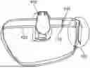
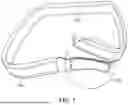

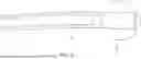

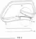
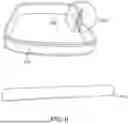
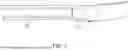
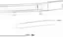


Sources:
- United States Patent and Trademark Office - verify current appl. status at the USPTO↗
Recent applications in this class:
- » 20260101947 2026-04-16
DUTY BELT - » 20260053221 2026-02-26
ADJUSTABLE BELT - » 20250374981 2025-12-11
MAGNETIC SUCTION TYPE WAIST BELT BUCKLE THAT CAN BE QUICKLY CLAMPED - » 20250325061 2025-10-23
Adjustable Belt System with Enhanced Comfort and Flexibility - » 20250311798 2025-10-09
Adjustable Fastening Device with Integrated Excess Material Management for Belts and Watch Bands - » 20250031790 2025-01-30
BELT WITH TAIL CLIP - » 20240389693 2024-11-28
BELT WITH U-SHAPED CLIPS - » 20240373962 2024-11-14
STRETCHABLE BELT - » 20240268498 2024-08-15
Customizable Decorative Belt - » 20240148090 2024-05-09
Belt For Wearing Around A Body Center