DUST COLLECTION BOX AND SELF-PROPELLED CLEANING DEVICE AND SYSTEM
US20260174296A1
2026-06-25
19/534,636
2026-02-09
Smart Summary: A dust collection box is designed to gather dirt and debris. It has a collection port on one side for easy access. When an object is cleaned and hits the opposite side, it falls into the box due to gravity. There is also an air outlet on another side, which helps with airflow. The shape of the box is specially designed to improve its dust-collecting ability. 🚀 TL;DR
Abstract:
A dust collection box includes: a first side wall provided with a collection port; a second side wall, wherein the second side wall is disposed opposite to the first side wall, and the second side wall is configured to, after being impacted by a cleaned object, allow the cleaned object to fall into the dust collection box under the action of gravity; and a third side wall provided with an air outlet, wherein an included angle between the third side wall and the first side wall is a first included angle, and the first included angle is greater than 90 degrees.
Inventors:
- Jun Wu 41 🇨🇳 Beijing, China
- Hongliang XU 9 🇨🇳 Beijing, China
- Baokui ZHANG 4 🇨🇳 Beijing, China
Assignee:
- Beijing Roborock Technology Co., Ltd. 63 🇨🇳 Beijing, China
Applicant:
Interested in similar patents?
Get notified when new applications in this technology area are published.
Classification:
A47L9/149 » CPC main
Details or accessories of suction cleaners, e.g. mechanical means for controlling the suction or for effecting pulsating action; Storing devices specially adapted to suction cleaners or parts thereof; Carrying-vehicles specially adapted for suction cleaners; Filters ; Dust separators; Dust removal; Automatic exchange of filters; Bags or the like; Attachment of, or closures for, bags Emptying means; Reusable bags
A47L9/1666 » CPC further
Details or accessories of suction cleaners, e.g. mechanical means for controlling the suction or for effecting pulsating action; Storing devices specially adapted to suction cleaners or parts thereof; Carrying-vehicles specially adapted for suction cleaners; Filters ; Dust separators; Dust removal; Automatic exchange of filters; Arrangement or disposition of cyclones or other devices with centrifugal action; Construction of outlets with filtering means
A47L9/1683 » CPC further
Details or accessories of suction cleaners, e.g. mechanical means for controlling the suction or for effecting pulsating action; Storing devices specially adapted to suction cleaners or parts thereof; Carrying-vehicles specially adapted for suction cleaners; Filters ; Dust separators; Dust removal; Automatic exchange of filters; Arrangement or disposition of cyclones or other devices with centrifugal action Dust collecting chambers; Dust collecting receptacles
A47L9/1691 » CPC further
Details or accessories of suction cleaners, e.g. mechanical means for controlling the suction or for effecting pulsating action; Storing devices specially adapted to suction cleaners or parts thereof; Carrying-vehicles specially adapted for suction cleaners; Filters ; Dust separators; Dust removal; Automatic exchange of filters; Arrangement or disposition of cyclones or other devices with centrifugal action Mounting or coupling means for cyclonic chamber or dust receptacles
A47L2201/00 » CPC further
Robotic cleaning machines, i.e. with automatic control of the travelling movement or the cleaning operation
A47L9/14 IPC
Details or accessories of suction cleaners, e.g. mechanical means for controlling the suction or for effecting pulsating action; Storing devices specially adapted to suction cleaners or parts thereof; Carrying-vehicles specially adapted for suction cleaners; Filters ; Dust separators; Dust removal; Automatic exchange of filters Bags or the like; Attachment of, or closures for, bags
A47L9/16 IPC
Details or accessories of suction cleaners, e.g. mechanical means for controlling the suction or for effecting pulsating action; Storing devices specially adapted to suction cleaners or parts thereof; Carrying-vehicles specially adapted for suction cleaners; Filters ; Dust separators; Dust removal; Automatic exchange of filters Arrangement or disposition of cyclones or other devices with centrifugal action
Description
CROSS-REFERENCE TO RELATED APPLICATION
The present application is a Continuation Application of International Application No. PCT/CN2024/110767, filed on August 8, 2024, which claims benefit of priority to Chinese Patent Application No. 202311084035.3 filed on August 25, 2023, the disclosure of both of which is incorporated herein by reference in its entirety as a part of the present application.
TECHNICAL FIELD
The present application relates to the technical field of cleaning devices, and in particular, to a dust collection box, a self-propelled cleaning device, and a self-propelled cleaning system.
BACKGROUND ART
In recent years, with the development of science and technology, various cleaning products have emerged one after another. These cleaning products reduce the workload of people in cleaning and sweeping, meet their needs, and bring great convenience to their lives. The automatic cleaning device is favored by people due to its high intelligence.
At present, sweeping robots on the market are all equipped with dust collection charging piles with two functions of charging and dust collection, and the dust collection charging piles have a special collection position for the sweeping robots to be charged and collect dust simultaneously. When a sweeping robot returns for recharging or collects dust, debris in a dust box inside the sweeping robot is sucked into a dust collection charging pile. The dust collection charging pile is provided with a collection bin with a larger volume. The collection bin can store debris, and users only need to clean the collection bin. During the process of dust suction, garbage is likely to cover the filter screen.
SUMMARY OF THE INVENTION
An objective of the present application is to provide a dust collection box, a self-propelled cleaning device, and a self-propelled cleaning system, which can solve the technical problem that garbage is likely to block a filter screen in the related art. Specific solutions are as follows.
According to a first aspect of the present application, a dust collection box is provided. The dust collection box includes: a first side wall provided with a collection port; a second side wall, where the second side wall is disposed opposite to the first side wall, and the second side wall is configured to, after being impacted by a cleaned object, allow the cleaned object to fall into the dust collection box under the action of gravity; and a third side wall provided with an air outlet, where an included angle between the third side wall and the first side wall is a first included angle, and the first included angle is greater than 90 degrees.
In some embodiments, the second side wall is arranged non-parallel to the first side wall.
In some embodiments, the dust collection box also includes: a fourth side wall, where the fourth side wall is disposed between the second side wall and the first side wall, the fourth side wall is provided with an air suction inlet, and an included angle between the fourth side wall and the first side wall is less than or equal to 90 degrees.
In some embodiments, the dust collection box also includes: an air suction baffle arranged at the air suction inlet, the air suction baffle being rotatably connected to the fourth side wall, where when the dust collection box is in a first state, the air suction baffle covers the air suction inlet; and when the dust collection box is in a second state, the air suction baffle is opened.
In some embodiments, when the air suction baffle is opened, an air suction direction is parallel to a plane on which the second side wall is located and faces the third side wall.
In some embodiments, the dust collection box also includes: a fifth side wall, where the fifth side wall is disposed between the second side wall and the third side wall.
In some embodiments, a junction between the fifth side wall and the second side wall is configured as a rounded corner.
In some embodiments, a projection of the second side wall in a direction of the first side wall is within a range of the first side wall.
According to another aspect of the present application, a self-propelled cleaning device is provided. The self-propelled cleaning device includes the dust collection box according to any one of the above technical solutions.
According to still another aspect of the present application, the present application provides a self-propelled cleaning system. The self-propelled cleaning system includes the self-propelled cleaning device according to any one of the above technical solutions.
Compared with the related art, the above solutions of the embodiments of the present application provide at least the following beneficial effects.
In the dust collection box of the present application, under the action of the dust suction fan, when garbage enters the dust collection cavity from the collection port, the garbage continues moving straight due to inertia and impacts on the second side wall, and then directly settles at the bottom of a dust box under the action of gravity, while air is discharged from the robot through an air outlet. The present application utilizes the principle of gravity for dust removal, and the included angle between the first side wall and the third side wall is greater than 90 degrees, forming an obtuse angle. The impact point of the garbage on the third side wall can be at a certain distance from the filter screen, thereby avoiding the influence on the service life of the filter screen and the dust collection efficiency caused by the garbage adhering to the filter screen.
BRIEF DESCRIPTION OF THE DRAWINGS
The drawings, which are incorporated into and constitute a part of the specification, illustrate embodiments consistent with the present application and are used in conjunction with the specification to explain the principles of the present application. Apparently, the drawings in the following description are merely some embodiments of the present application, and those of ordinary skill in the art may still derive other drawings from these drawings without creative efforts. In the drawings:
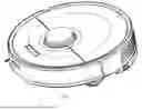
FIG. 1 is a schematic structural diagram of a self-propelled cleaning device according to some embodiments of the present application.
FIG. 2 is a schematic diagram of a bottom structure of the self-propelled cleaning device as shown in FIG. 1.
FIG. 3 is a schematic structural diagram of a dust collection box and a self-propelled cleaning device that are not assembled together according to some embodiments of the present application.
FIG. 4 is a schematic structural diagram of a dust collection charging pile according to some embodiments of the present application.
FIG. 5 is a schematic diagram of a scenario after a self-propelled cleaning device returns to a dust collection charging pile according to some embodiments of the present application.
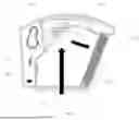
FIG. 6 shows a schematic diagram of a dust collection box according to some embodiments of the present application, where a direction of airflow movement in the dust collection box when an automatic cleaning device performs a cleaning operation is shown.
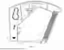
FIG. 7 shows a schematic diagram of a dust collection box according to some embodiments of the present application, where a direction of airflow movement in the dust collection box when an automatic cleaning device returns to a dust collection pile for dust collection is shown.
FIG. 8 shows a schematic diagram of a dust collection box according to some embodiments of the present application, in which relative angular relationships among side walls are indicated.
FIG. 9 shows a schematic diagram of a dust collection box according to some embodiments of the present application, where a direction of airflow movement in the dust collection box when an automatic cleaning device performs a cleaning operation is shown.
Reference numerals:
100: first side wall; 200: second side wall; 300: third side wall; 310: filter screen; 400: fourth side wall; 410: air suction baffle; 500: fifth side wall; 510: dust blocking part; 10: dust collection cavity; 20: collection port; 30: air suction inlet.
600: self-propelled cleaning device; 610: cleaning module; 611: roller brush; 6111: scraping strip; 612: framework; 6121: vent opening; 620: steering wheel; 630: driving wheel; 640: charging electrode; 650: accommodating space; 651: second opening; 652: air vent; 660: dust suction fan; 670: dust collection box.
700: dust collection charging pile; 710: dust collection charging pile base; 711: dust suction inlet; 712: sealing gasket; 713: dust collection air passage; 720: dust collection charging pile body; 721: charging connector; 722: dust collection container; 723: dust collection fan.
α1: first included angle; α2: second included angle; α3: third included angle.
The direction of the arrows in the figures indicates the direction of airflow.
DETAILED DESCRIPTION
For clearer descriptions of the objectives, technical solutions, and advantages of the present application, the present application is further described in detail hereinafter with reference to the drawings. Apparently, the described embodiments are merely some embodiments of the present application, rather than all of the embodiments. Based on the embodiments in the present application, all other embodiments obtained by those of ordinary skill in the art without creative efforts shall fall within the protection scope of the present application.
The terms used in the embodiments of the present application are for the purpose of describing particular embodiments only and are not intended to limit the present application. As used in the embodiments and the appended claims of the present application, the singular forms “a”, “an”, and “the” are intended to include the plural forms as well, unless the context clearly indicates otherwise, and “plurality of” generally includes at least two.
It should be understood that the term “and/or” as used herein is merely a way to describe an association relationship between associated objects, indicating that three possible relationships may exist. For example, “A and/or B” can represent: the existence of A alone, the simultaneous existence of A and B, and the existence of B alone. In addition, the character “/” herein generally indicates an “or” relationship between the associated objects before and after.
It should be understood that although the terms “first”, “second”, “third”, and the like may be used in the embodiments of the present application to describe ..., these ... should not be limited by these terms. These terms are only used to distinguish between... For example, “first ...” may also be referred to as “second ...”, and similarly, “second ...” may also be referred to as “first ...”, without departing from the scope of the embodiments of the present application.
Depending on the context, the term “if” as used herein may be interpreted as “when”, “in the event that”, “in response to determining”, or “in response to detecting”. Similarly, depending on the context, the phrases “if it is determined” or “if (a stated condition or event) is detected” may be interpreted as “when it is determined” or “in response to determining”, or “when (a stated condition or event) is detected” or “in response to detecting (a stated condition or event)”.
It should be further noted that the terms “comprise”, “include”, or any other variants thereof, are intended to encompass a non-exclusive inclusion, such that an article or apparatus including a list of elements includes not only those elements, but also other elements not explicitly listed or inherent to such an article or apparatus. Without further limitation, an element defined by the phrase “comprising a/an…” or “including a/an…” does not exclude the presence of other identical elements in the article or apparatus including the element.
In the related art, when the self-propelled cleaning device returns for recharging or collects dust, debris in a dust collection box inside the self-propelled cleaning device is sucked into a dust collection charging pile 700. The dust collection charging pile 700 is provided with a collection bin with a larger volume. The collection bin can store debris, and users only need to clean the collection bin. During a dust suction process of the self-propelled cleaning device, garbage is likely to cover a filter screen or even cause the filter screen to be completely clogged, thereby reducing the dust suction efficiency and failing to clean local garbage when collecting dust.
The present application provides a dust collection box 670, a self-propelled cleaning device, and a self-propelled cleaning device system. The dust collection box may include: a first side wall 100 provided with a collection port 20; a second side wall 200, where the second side wall 200 is disposed opposite to the first side wall 100, and the second side wall 200 is configured to, after being impacted by a cleaned object (cleaned garbage), allow the cleaned object to fall into the dust collection box 670 under the action of gravity; and a third side wall 300 provided with an air outlet, where an included angle between the third side wall 300 and the first side wall 100 is a first included angle α1, and the first included angle α1 is greater than 90 degrees.
The technical solutions of the present application can solve at least one of the technical problems mentioned above. Optional embodiments of the present application will be described in detail hereinafter with reference to the drawings.
FIG. 1 is a schematic structural diagram of a self-propelled cleaning device according to some embodiments of the present application.
FIG. 2 is a schematic diagram of a bottom structure of the self-propelled cleaning device as shown in FIG. 1.
As shown in FIGS. 1 and 2, the self-propelled cleaning device 600, such as a sweeping robot, may include a steering wheel 620 and a driving wheel 630. Under the action of the steering wheel 620 and the driving wheel 630, the self-propelled cleaning device 600 may move on a supporting surface, such as the ground. Optionally, the self-propelled cleaning device 600 may move according to a preset route, and in a specific situation, for example, when the self-propelled cleaning device 600 itself has insufficient power, a dust box of the self-propelled cleaning device 600 itself is fully loaded with garbage, or a sweeping work is completed, the self-propelled cleaning device 600 may move back to the dust collection charging pile to complete charging or unload garbage into a dust collection container.
The self-propelled cleaning device 600 may also include a charging electrode 640 configured to be electrically connected to the dust collection charging pile to charge the self-propelled cleaning device 600 after the self-propelled cleaning device 600 returns to the dust collection charging pile. As shown in FIG. 2, in some embodiments, the charging electrode 640 is disposed on a bottom surface of the self-propelled cleaning device 600, and the number of charging electrodes is, for example, two, which are arranged on two sides of the steering wheel 620, respectively. Those skilled in the art can understand that the above is only an example of the number and arrangement position of the charging electrode, and the present application does not specifically limit the number and arrangement position of the charging electrode.
The self-propelled cleaning device 600 may also include a cleaning module 610, such as a dry cleaning module. The cleaning module 610 is configured to clean at least part of the supporting surface (e.g., the ground) when the self-propelled cleaning device 600 moves on the supporting surface. In some embodiments, as shown in FIG. 2, the cleaning module 610 is, for example, disposed between two driving wheels 630. The cleaning module 610 may specifically include a framework 612 and a roller brush 611 arranged within the framework 612. The outer periphery of the roller brush 611 is provided with a plurality of scraping strips 6111. The framework 612 is provided with a vent opening 6121, and the vent opening 6121 exposes at least part of the roller brush 611.
When the self-propelled cleaning device 600 performs a cleaning operation, the roller brush 611 rotates, and the scraping strips 6111 exposed by the framework 612 on the roller brush may be in contact with the ground. Meanwhile, a fan in the self-propelled cleaning device 600, such as a dust suction fan, generates an airflow entering the framework 612 via the vent opening 6121. Under the action of the scraping strips 6111 and the airflow, garbage may enter the framework 612 via the vent opening 6121 and then be collected into the dust box of the self-propelled cleaning device 600. The vent opening 6121 further serves as a circulation port of the garbage; that is, when the self-propelled cleaning device 600 performs a cleaning operation, the vent opening 6121 serves as a dust suction inlet of the self-propelled cleaning device 600.
FIG. 3 is a schematic structural diagram of a dust collection box and a self-propelled cleaning device that are not assembled together according to some embodiments of the present application.
As shown in FIG. 3, the self-propelled cleaning device 600 also includes a dust suction fan 660. The dust suction fan 660 is located within the self-propelled cleaning device 600 and is not shown in the figure. The dust suction fan 660 is configured to provide a suction power source for generating an airflow when the self-propelled cleaning device 600 performs a cleaning operation. When the self-propelled cleaning device 600 performs the cleaning operation, under the action of the airflow generated by the dust suction fan 660, garbage enters the framework 612 via the vent opening 6121 and is then collected into the dust collection box 670 of the self-propelled cleaning device 600.
The self-propelled cleaning device 600 is provided with an accommodating space 650, and the accommodating space 650 is configured to accommodate the dust collection box 670. A side wall of the accommodating space 650 is provided with a second opening 651 and an air vent 652, and both the second opening 651 and the air vent 652 are in communication with the environment. When the self-propelled cleaning device 600 performs a cleaning operation, garbage enters the dust collection box 670 via the vent opening 6121 and the second opening 651. The air vent 652 is configured to allow external air to enter the dust collection box 670 via the air vent 652 when the self-propelled cleaning device 600 returns to the dust collection charging pile 700 for dust collection.
FIG. 4 is a schematic structural diagram of a dust collection charging pile according to some embodiments of the present application.
The dust collection charging pile 700 integrates a charging pile and a dust collection pile, and is configured to provide energy supply for the self-propelled cleaning device and perform garbage collection.
As shown in FIG. 4, the dust collection charging pile 700 includes a dust collection charging pile base 710 and a dust collection charging pile body 720. The dust collection charging pile body 720 is configured to charge the self-propelled cleaning device 600 and collect the garbage in the dust collection box 670 of the self-propelled cleaning device 600, and the dust collection charging pile body is arranged on the dust collection charging pile base 710. The dust collection charging pile body 720 includes a dust collection container 722 and a dust collection fan 723. The dust collection container 722 is, for example, in a cylindrical shape and is configured to collect garbage in the dust collection box 670 of the self-propelled cleaning device 600. The dust collection fan 723 is connected to an air outlet arranged in the dust collection container 722, so as to provide power for collecting the garbage in the dust collection box 670 of the self-propelled cleaning device 600 into the dust collection container 722.
The dust collection charging pile 700 includes a charging connector 721 and a dust suction inlet 711. The charging connector 721 is configured to supply energy to the self-propelled cleaning device 600, and the dust suction inlet 711 is configured to be docked with a dust outlet of the self-propelled cleaning device 600 (when the self-propelled cleaning device 600 discharges dust into the dust collection charging pile 700, the vent opening 6121 in the self-propelled cleaning device 600 serves as the dust outlet). The garbage in the dust collection box 670 of the self-propelled cleaning device 600 enters the dust collection container 722 of the dust collection charging pile body 720 via the dust suction inlet 711. For example, as shown in FIG. 4, the charging connector 721 is arranged on the dust collection charging pile body 720, and the dust suction inlet 711 is arranged on the dust collection charging pile base 710. In some embodiments, as shown in FIG. 4, a sealing gasket 712 is also provided around the dust suction inlet 711 for sealing the dust suction inlet 711 after docking with the dust outlet of the self-propelled cleaning device 600, so as to prevent garbage leakage.
An air inlet of the dust collection container 722 is in communication with the dust suction inlet 711 via a dust collection air passage 713. Under the action of the airflow generated by the dust collection fan 723, the garbage in the dust collection box 670 of the self-propelled cleaning device 600 can pass through the vent opening 6121 in the self-propelled cleaning device 600 and then be collected in the dust collection container 722 via the dust collection air passage 713.
FIG. 5 is a schematic diagram of a scenario after a self-propelled cleaning device returns to a dust collection charging pile according to some embodiments of the present application.
As shown in FIG. 5, after the self-propelled cleaning device 600, such as a sweeping robot, completes cleaning and returns to the dust collection charging pile 700, the self-propelled cleaning device 600 moves to the dust collection charging pile base 710 in a first direction X, such that the charging electrode 640 on the self-propelled cleaning device 600 is electrically connected to the charging connector 721 to charge the self-propelled cleaning device 600, and the dust outlet, i.e., the vent opening 6121, of the self-propelled cleaning device 600 is docked with the dust suction inlet 711 of the dust collection charging pile 700, so as to transfer the garbage in the dust collection box 670 of the self-propelled cleaning device 600 to the dust collection container 722 of the dust collection charging pile 700.
FIG. 6 shows a schematic diagram of a dust collection box according to some embodiments of the present application, where a direction of airflow movement in the dust collection box when an automatic cleaning device performs a cleaning operation is shown. FIG. 7 shows a schematic diagram of a dust collection box according to some embodiments of the present application, where a direction of airflow movement in the dust collection box when an automatic cleaning device returns to a dust collection pile for dust collection is shown. FIG. 8 shows a schematic diagram of a dust collection box according to some embodiments of the present application, in which relative angular relationships among side walls are indicated.
As shown in FIGS. 6 to 8, according to a first aspect of the present application, a dust collection box 670 is provided. The dust collection box may include: a first side wall 100 provided with a collection port 20; a second side wall 200, where the second side wall 200 is disposed opposite to the first side wall 100, and the second side wall 200 is configured to, after being impacted by a cleaned object (cleaned garbage), allow the cleaned object to fall into the dust collection box 670 under the action of gravity; and a third side wall 300 provided with an air outlet, where the air outlet is configured for arranging a filter screen 310. One end of the third side wall 300 away from the second side wall 200 is connected to the first side wall 100; an included angle between the third side wall 300 and the first side wall 100 is a first included angle α1, and the first included angle α1 is greater than 90 degrees. In some embodiments, a space inside the first side wall 100, the second side wall 200, and the third side wall 300 is a dust collection cavity 10. In the dust collection box 670 of the present application, under the action of the dust suction fan 660, when garbage enters the dust collection cavity 10 from the collection port 20, the garbage continues moving straight due to inertia and impacts on the second side wall 200, and then directly settles at the bottom of the dust box under the action of gravity, while air is discharged from the robot through the air outlet. The present application utilizes the principle of gravity for dust removal, and the included angle between the first side wall 100 and the third side wall 300 is greater than 90 degrees, forming an obtuse angle. The impact point of the garbage on the third side wall 300 can be at a certain distance from the filter screen, thereby avoiding the influence on the service life of the filter screen and the dust collection efficiency caused by the garbage adhering to the filter screen.
Actual application scenarios may include the following scenarios.
Scenario 1: Dust suction: During a sweeping process of the self-propelled cleaning device 600, the dust collection box 670 is placed at a corresponding position of the self-propelled cleaning device 600, and the dust suction fan 660 in the self-propelled cleaning device 600 sucks air at one end of the filter screen 310 away from the dust collection cavity 10. The power of the dust suction fan 660 is insufficient to open the air suction baffle 410. In this case, the air suction baffle 410 is closed. Due to the suction force of the dust suction fan 660, the cleaned garbage follows the airflow, entering the dust collection cavity 10 from the collection port 20. The garbage continues moving straight due to inertia and impacts on the second side wall 200, then loses forward kinetic energy, and directly settles at the bottom of the dust box under the action of gravity. Air is discharged from the self-propelled cleaning device 600 through the air outlet, while the garbage is left in the dust collection cavity 10.
Scenario 2: Dust collection: When the self-propelled cleaning device 600 returns to the dust collection charging pile 700 (for charging, water replenishment, water changing, or dust collection), the dust collection box 670 is placed at a corresponding position of the self-propelled cleaning device 600, and the collection port 20 corresponds to the dust collection fan 723 of the dust collection charging pile 700. The dust collection fan 723 and the dust suction fan 660 operate simultaneously. Due to the negative pressure within the dust collection cavity 10, the air suction baffle 410 is opened, the airflow enters from the air suction inlet 30 and flows toward the fifth side wall 500 in a direction parallel to the second side wall 200, and the wind direction changes upon encountering the fifth side wall 500. Since the wind force of the dust collection fan 723 is greater than that of the dust suction fan 660, the sucked air forms an annular cyclone, which can more effectively take away the garbage in the dust collection cavity 10, without dead corners for garbage remaining compared with the original rectangular dust box, thereby improving the dust collection efficiency.
In some embodiments, the second side wall 200 is arranged non-parallel to the first side wall 100. In some embodiments, an included angle between the second side wall 200 and the first side wall 100 is a second included angle α2, and the second angle α2 is less than 90 degrees (as shown in FIG. 8). In order to ensure that, during dust suction, garbage entering the dust collection cavity 10 can impact on the second side wall 200, lose forward kinetic energy, and directly settle at the bottom of the dust box under the action of gravity, the second included angle α2 is less than 90 degrees.
In some embodiments, the filter screen 310 is a detachable structure. The filter screen 310 can be detached from the third side wall 300, facilitating subsequent maintenance, cleaning, and replacement.
As shown in FIGS. 6 to 8, in some embodiments, the dust collection box may also include a fourth side wall 400, and the fourth side wall 400 is disposed between the second side wall 200 and the first side wall 100. The fourth side wall 400 is provided with an air suction inlet 30, and an included angle between the fourth side wall 400 and the first side wall 100 is less than or equal to 90 degrees. The air sucked in through the air suction inlet 30 forms an annular cyclone, which can more effectively take away the garbage in a dust collection cavity 10, without dead corners for garbage remaining compared with the original rectangular dust box, thereby improving the dust collection efficiency.
In some embodiments, the dust collection box 670 may also include an air suction baffle 410 arranged at the air suction inlet 30, and the air suction baffle 410 is rotatably connected to the fourth side wall 400.
In some embodiments, when the dust collection box 670 is in a first state, that is, when the automatic cleaning device is in a non-dust collection state, the air suction baffle 410 covers the air suction inlet 30.
As shown in FIGS. 6 to 8, in some embodiments, when the dust collection box 670 is in a second state, that is, when the automatic cleaning device returns to the dust collection pile and is in a dust collection state, the air suction baffle 410 is opened. The dust collection box 670 is placed at a corresponding position of the self-propelled cleaning device 600, and the collection port 20 corresponds to the dust collection fan 723 of the dust collection charging pile 700. The dust collection fan 723 and the dust suction fan 660 operate simultaneously. Due to the negative pressure within the dust collection cavity 10, the air suction baffle 410 is opened, the airflow enters from the air suction inlet 30 and flows toward the fifth side wall 500 in the direction parallel to the second side wall 200, and the wind direction changes upon encountering the fifth side wall 500. Since the wind force of the dust collection fan 723 is greater than that of the dust suction fan 660, the sucked air forms an annular cyclone, which can more effectively take away the garbage in the dust collection cavity 10, without dead corners for garbage remaining compared with the original rectangular dust box, thereby improving the dust collection efficiency.
The first state is a dust suction state of the self-propelled cleaning device 600, that is, a state in which the automatic cleaning robot is cleaning.
The second state is a dust collection state of the self-propelled cleaning device 600, that is, a state in which the automatic cleaning robot is on the dust collection charging pile 700 and transfers the garbage in the dust collection cavity 10 to a dust collection bin in the dust collection charging pile 700.
In some embodiments, when the air suction baffle 410 is opened, the air suction baffle 410 and the fourth side wall 400 form a third included angle α3.
In some embodiments, the third included angle α3 and the second included angle α2 are complementary to each other.
In some embodiments, a first angle is defined as 90 degrees minus the second included angle α2.
In some embodiments, the third included angle α3 is less than or equal to the first angle.
When the air suction baffle 410 is parallel to the second side wall 200, the third included angle α3 and the second included angle are complementary to each other. When the third included angle α3 is greater than the first angle, the airflow direction is more biased to a direction of the third side wall 300. When the third included angle α3 is less than the first angle, the airflow direction is more biased to a direction of the second side wall 200.
In the case that the airflow direction is biased to the direction of the second side wall 200, an annular cyclone can be formed.
As shown in FIGS. 6 to 8, the airflow sucked into the dust collection cavity 10 is close to the second side wall 200, and rebounds from the second side wall 200 or the third side wall 300 to form an annular cyclone, which can more effectively take away the garbage in the dust collection cavity 10, without dead corners for garbage remaining compared with the original rectangular dust box, thereby improving the dust collection efficiency.
In some embodiments, when the air suction baffle 410 is opened, an air suction direction is parallel to a plane on which the second side wall 200 is located and faces the third side wall 300.
In some embodiments, the dust collection box 670 may also include a fifth side wall 500, and the fifth side wall 500 is disposed between the second side wall 200 and the third side wall 300.
In some embodiments, a space inside the first side wall 100, the second side wall 200, the third side wall 300, the fourth side wall 400, and the fifth side wall 500 is the dust collection cavity 10; that is, a space enclosed by the first side wall 100, the second side wall 200, the third side wall 300, the fourth side wall 400, and the fifth side wall 500 is the dust collection cavity 10.
In some embodiments, a junction between the fifth side wall 500 and the second side wall 200 is configured as a rounded corner. The first corner encountered by the airflow entering the dust collection cavity 10 from the air suction inlet 30 is at the junction between the fifth side wall 500 and the second side wall 200. Therefore, the junction is configured as a rounded corner, which makes it easier for the airflow to form an annular cyclone and effectively reduces the loss of kinetic energy of the airflow. As a result, the garbage in the dust collection cavity 10 can be taken away more effectively without dead corners for garbage remaining, thereby improving the dust collection efficiency.
In some embodiments, the fifth side wall 500 is curved and is provided with a recess on one side close to the dust collection cavity 10. The fifth side wall 500 is designed to be curved and protrude outward from the dust collection cavity 10, which makes it easier for the airflow to form an annular cyclone and effectively reduces the loss of kinetic energy of the airflow. As a result, the garbage in the dust collection cavity 10 can be taken away more effectively without dead corners for garbage remaining, thereby improving the dust collection efficiency.
As shown in FIGS. 6 to 8, in some embodiments, an included angle, which is formed between the third side wall 300 and the first side wall 100 and close to the side of the dust collection cavity 10, is the first included angle α1.
In some embodiments, an included angle, which is formed between an extension line of the second side wall 200 and an extension line of the first side wall 100 and close to the side of the dust collection cavity 10, is the second included angle α2.
In some embodiments, an included angle, which is formed between the air suction baffle 410 and the fourth side wall 400 and away from the first side wall 100, is the third included angle α3.
FIG. 9 shows a schematic diagram of a dust collection box according to some embodiments of the present application, where a direction of airflow movement in the dust collection box when an automatic cleaning device performs a cleaning operation is shown.
As shown in FIG. 9, in some embodiments, the fifth side wall 500 is provided with a dust blocking part 510, and the dust blocking part 510 extends in the direction of the collection port 20.
In some embodiments, corners of an inner wall of the dust collection cavity 10 may all be rounded corners. The airflow entering the dust collection cavity 10 from the air suction inlet 30 encounters a corner, which reduces the kinetic energy of the airflow. Therefore, a rounded corner is provided, which makes it easier for the airflow to form an annular cyclone and effectively reduces the loss of kinetic energy of the airflow. As a result, the garbage in the dust collection cavity 10 can be taken away more effectively without dead corners for garbage remaining, thereby improving the dust collection efficiency.
In some embodiments, the projection of the second side wall 200 in a direction of the first side wall 100 is within a range of the first side wall 100. The distance between the second side wall 200 and the third side wall 300 may be increased; that is, the impact point of the sucked garbage on the second side wall 200 can be at a certain distance from the filter screen, thereby avoiding the influence on the service life of the filter screen and the dust collection efficiency caused by the garbage adhering to the filter screen.
In some embodiments, the dust collection box 670 may also include a top plate, and the top plate is perpendicular to the first side wall 100, the second side wall 200, the third side wall 300, the fourth side wall 400, and the fifth side wall 500. During the use of the self-propelled cleaning device 600, the top plate faces upward.
In some embodiments, the dust collection box 670 may also include a bottom plate, and the top plate is perpendicular to the first side wall 100, the second side wall 200, the third side wall 300, the fourth side wall 400, and the fifth side wall 500. The bottom plate is disposed opposite to the top plate. During the use of the self-propelled cleaning device 600, the bottom plate faces downward.
In some embodiments, the top plate in the dust collection cavity 10 is provided with a flow guide groove.
In some embodiments, the flow guide groove is annular.
In some embodiments, one end of the flow guide groove close to the second side wall 200 is consistent with the air suction direction and is located above the air suction airflow.
In some embodiments, a plurality of flow guide grooves are provided, and the plurality of flow guide grooves are arranged in parallel. One end of the outermost flow guide groove close to the second side wall 200 is consistent with the air suction direction and is located above the air suction airflow.
In some embodiments, the flow guide groove is spiral.
In some embodiments, an outermost inlet of the flow guide groove is provided above the air suction baffle 410.
By providing the flow guide groove in the dust collection cavity 10, the airflow sucked into the dust collection cavity 10 can move in a direction of the flow guide groove to a certain extent, such that the airflow sucked into the dust collection cavity 10 forms an annular cyclone. As a result, the garbage in the dust collection cavity 10 can be taken away more effectively, without dead corners for garbage remaining compared with the original rectangular dust box, thereby improving the dust collection efficiency.
According to a second aspect of the present application, a self-propelled cleaning device 600 is provided. The self-propelled cleaning device may include the dust collection box 670 according to any one of the above technical solutions.
According to a third aspect of the present application, a self-propelled cleaning system is provided. The self-propelled cleaning system may include the self-propelled cleaning device 600 according to any one of the above technical solutions.
In some embodiments, the self-propelled cleaning system may also include a dust collection charging pile 700. The dust collection charging pile 700 responds to the self-propelled cleaning device 600 according to any one of the above technical solutions. The garbage in the dust collection box 670 of the self-propelled cleaning device 600 is collected into a dust collection bin body of the dust collection charging pile 700 via the collection port 20.
In some embodiments, the dust collection charging pile 700 may include a dust collection fan 723. The dust collection fan 723 is configured to suck out the garbage in the dust collection cavity 10 via the collection port 20, and the suction force of the dust collection fan 723 is greater than that of the dust suction fan 660.
The present application is intended to protect a dust collection box 670, a self-propelled cleaning device, and a self-propelled cleaning system. The dust collection box 670 may include: a first side wall 100 provided with a collection port 20; a second side wall 200, where the second side wall 200 is disposed opposite to the first side wall 100, and the second side wall 200 is configured to, after being impacted by a cleaned object (cleaned garbage), allow the cleaned object to fall into the dust collection box 670 under the action of gravity; and a third side wall 300 provided with an air outlet, where an included angle between the third side wall 300 and the first side wall 100 is a first included angle α1, and the first included angle α1 is greater than 90 degrees. In the dust collection box 670 of the present application, under the action of the dust suction fan 660, when garbage enters the dust collection cavity 10 from the collection port 20, the garbage continues moving straight due to inertia and impacts on the second side wall 200, and then directly settles at the bottom of the dust box under the action of gravity, while air is discharged from the robot through the air outlet. The present application utilizes the principle of gravity for dust removal, and the included angle between the first side wall 100 and the third side wall 300 is greater than 90 degrees, forming an obtuse angle. The impact point of the garbage on the third side wall 300 can be at a certain distance from the filter screen, thereby avoiding the influence on the service life of the filter screen and the dust collection efficiency caused by the garbage adhering to the filter screen.
It should be understood that the above specific embodiments of the present application are only used to exemplarily illustrate or explain the principles of the present application, and do not constitute a limitation on the present application. Therefore, any modification, equivalent substitution, improvement, or the like made without departing from the spirit and scope of the present application shall fall within the protection scope of the present application. Furthermore, the appended claims of the present application are intended to encompass all changes and modifications that fall within the scope and boundaries of the appended claims, or equivalents of such scope and boundaries.
Claims
1. A dust collection box, comprising:
a first side wall provided with a collection port;
a second side wall, wherein the second side wall is disposed opposite to the first side wall, and the second side wall is configured to, after being impacted by a cleaned object, allow the cleaned object to fall into the dust collection box under the action of gravity; and
a third side wall provided with an air outlet, wherein an included angle between the third side wall and the first side wall is a first included angle, and the first included angle is greater than 90 degrees.
2. The dust collection box according to claim 1, wherein,
the second side wall is arranged non-parallel to the first side wall.
3. The dust collection box according to claim 1, further comprising:
a fourth side wall, wherein the fourth side wall is disposed between the second side wall and the first side wall, the fourth side wall is provided with an air suction inlet, and an included angle between the fourth side wall and the first side wall is less than or equal to 90 degrees.
4. The dust collection box according to claim 3, further comprising:
an air suction baffle arranged at the air suction inlet, the air suction baffle being rotatably connected to the fourth side wall,
wherein when the dust collection box is in a first state, the air suction baffle covers the air suction inlet; and
when the dust collection box is in a second state, the air suction baffle is opened.
5. The dust collection box according to claim 4, wherein the first state is a dust suction state for cleaning the cleaned object, and the second state is a dust collection state for transferring the cleaned object.
6. The dust collection box according to claim 4, wherein,
when the air suction baffle is opened, an air suction direction is parallel to a plane on which the second side wall is located and faces the third side wall.
7. The dust collection box according to claim 1, further comprising:
a fifth side wall, wherein the fifth side wall is disposed between the second side wall and the third side wall.
8. The dust collection box according to claim 7, wherein,
a junction between the fifth side wall and the second side wall is configured as a rounded corner.
9. The dust collection box according to claim 1, wherein,
a projection of the second side wall in a direction of the first side wall is within a range of the first side wall.
10. The dust collection box according to claim 1, wherein the air outlet is configured for arranging a filter screen, and an impact point of the cleaned object on the third side wall is at a certain distance from the filter screen.
11. The dust collection box according to claim 4, wherein a second included angle between the second side wall and the first side wall is less than 90 degrees.
12. The dust collection box according to claim 11, wherein the air suction baffle and the fourth side wall form a third included angle, and the third included angle and the second included angle are complementary to each other.
13. The dust collection box according to claim 12, wherein a first angle is defined as 90 degrees minus the second included angle, and the third included angle is less than or equal to the first angle.
14. The dust collection box according to claim 3, wherein the dust collection box futher comprises a fifth side wall; a space enclosed by the first side wall, the second side wall, the third side wall, the fourth side wall and the fifth side wall is a dust collection cavity; and the fifth side wall is curved and is provided with a recess on one side close to the dust collection cavity.
15. A self-propelled cleaning device, comprising a dust collection box, wherein the dust collection box comprises:
a first side wall provided with a collection port;
a second side wall, wherein the second side wall is disposed opposite to the first side wall, and the second side wall is configured to, after being impacted by a cleaned object, allow the cleaned object to fall into the dust collection box under the action of gravity; and
a third side wall provided with an air outlet, wherein an included angle between the third side wall and the first side wall is a first included angle, and the first included angle is greater than 90 degrees.
16. The self-propelled cleaning device according to claim 15, wherein the second side wall is arranged non-parallel to the first side wall.
17. The self-propelled cleaning device according to claim 15, wherein the the dust collection box further comprises:
a fourth side wall, wherein the fourth side wall is disposed between the second side wall and the first side wall, the fourth side wall is provided with an air suction inlet, and an included angle between the fourth side wall and the first side wall is less than or equal to 90 degrees.
18. A self-propelled cleaning system, comprising:
a self-propelled cleaning device; and
a dust collection pile;
wherein the self-propelled cleaning device comprises a dust collection box, and the dust collection box comprises:
a first side wall provided with a collection port;
a second side wall, wherein the second side wall is disposed opposite to the first side wall, and the second side wall is configured to, after being impacted by a cleaned object, allow the cleaned object to fall into the dust collection box under the action of gravity; and
a third side wall provided with an air outlet, wherein an included angle between the third side wall and the first side wall is a first included angle, and the first included angle is greater than 90 degrees.
19. The self-propelled cleaning system according to claim 18, wherein the second side wall is arranged non-parallel to the first side wall.
20. The self-propelled cleaning system according to claim 18, wherein the the dust collection box further comprises:
a fourth side wall, wherein the fourth side wall is disposed between the second side wall and the first side wall, the fourth side wall is provided with an air suction inlet, and an included angle between the fourth side wall and the first side wall is less than or equal to 90 degrees.
Images & Drawings included:


Sources:
- United States Patent and Trademark Office - verify current appl. status at the USPTO↗
Recent applications in this class:
- » 20260137250 2026-05-21
DISPOSABLE CONTAINER FOR CONSTRUCTION-GRADE VACUUM CLEANERS - » 20260114686 2026-04-30
CLEANING SYSTEM - » 20260083290 2026-03-26
CLEANING DEVICE HAVING VACUUM CLEANER AND DOCKING STATION AND METHOD OF CONTROLLING THE SAME - » 20260076520 2026-03-19
CLEANER STATION WITH COVER OPENING UNIT - » 20260053313 2026-02-26
AIR TREATMENT UNIT - » 20260053312 2026-02-26
WASHABLE BIN FOR A ROBOT VACUUM CLEANER - » 20260053311 2026-02-26
HAND VACUUM CLEANER AND AUTO-EMPTY DOCK - » 20260013689 2026-01-15
VACUUM CLEANER - » 20260000256 2026-01-01
CLEANING APPARATUS - » 20250359715 2025-11-27
CLEANING APPARATUS HAVING VACUUM CLEANER AND DOCKING STATION
Recent applications for this Assignee:
- » 20260169530 2026-06-18
CLEANING BASE STATION - » 20260165541 2026-06-18
ACCOMMODATING DEVICE, SELF-MOVING CLEANING DEVICE, AND SELF-MOVING CLEANING SYSTEM - » 20260157589 2026-06-11
CLEANING DEVICE - » 20260140233 2026-05-21
RANGING APPARATUS AND SELF-PROPELLED DEVICE - » 20260083297 2026-03-26
AUTOMATIC CLEANING DEVICE, AND SYSTEM - » 20260083293 2026-03-26
CHARGING CONTROL METHOD, NON-TRANSITORY COMPUTER-READABLE STORAGE MEDIUM AND CLEANING ROBOT - » 20260079254 2026-03-19
DISTANCE DETECTION APPARATUS AND SELF-PROPELLED DEVICE - » 20260033694 2026-02-05
CLEANING ROBOT SYSTEM - » 20260026667 2026-01-29
RANGING APPARATUS AND CLEANING ROBOT - » 20260013697 2026-01-15
BASE STATION AND CLEANING ROBOT SYSTEM