LOCALIZED RAPID COOLING FOR METAL FORMING
US20260175280A1
2026-06-25
19/366,383
2025-10-22
Smart Summary: Metal parts are first heated in a furnace to make them easier to shape. After heating, a forming tool is used to mold the metal into a specific part. To cool certain thick areas of the part quickly, a cooling fluid is sprayed only on those targeted sections, avoiding the thinner areas. The tool has special nozzles that direct the cooling fluid precisely where it's needed. This method helps improve the quality and performance of the final metal part. 🚀 TL;DR
Abstract:
Localized rapid cooling for metal forming is described. A metallic blank is heated in a furnace. The metallic blank is formed into a metallic part with a forming tool. Target portions of the metallic part are cooled by locally spraying cooling fluid from the forming tool onto the one or more target portions, without spraying the cooling fluid onto at least some non-target portions. The target portions comprise relatively thick portions of the metallic part compared to other areas of the metallic part. The forming tool comprises one or more cooling elements, such as nozzles, located in proximity to the relatively thick portions so as to spray the cooling fluid onto, and locally cool, the relatively thick areas of the metallic part.
Inventors:
- Victor Manuel CASTILLO 1 🇲🇽 Puebla, Mexico
- Victor Manuel ESTEVEZ 1 🇲🇽 Puebla, Mexico
- Alejandro GORRAEZ ALEJANDRE 1 🇲🇽 Puebla, Mexico
Applicant:
Interested in similar patents?
Get notified when new applications in this technology area are published.
Classification:
B21D22/022 » CPC main
Shaping without cutting, by stamping, spinning, or deep-drawing; Stamping using rigid devices or tools by heating the blank or stamping associated with heat treatment
C22F1/002 » CPC further
Changing the physical structure of non-ferrous metals or alloys by heat treatment or by hot or cold working by rapid cooling or quenching; cooling agents used therefor
B21D22/02 IPC
Shaping without cutting, by stamping, spinning, or deep-drawing Stamping using rigid devices or tools
C22F1/00 IPC
Changing the physical structure of non-ferrous metals or alloys by heat treatment or by hot or cold working
Description
CROSS REFERENCE TO RELATED APPLICATIONS
This application claims priority to U.S. Provisional Application No. 63/737,016 filed on Dec. 20, 2024, and U.S. Provisional Application No. 63/788,220 filed on Apr. 14, 2025, and which are incorporated herein in their entireties by reference.
BACKGROUND OF THE INVENTION
1. Field of the Invention
The present disclosure relates to localized rapid cooling for metal forming.
2. Description of Related Art
Processes for forming metallic parts are known. Many of these processes cool formed parts using tooling components that include cooling channels, or tooling components made with metals that have relatively high thermal conductivity.
SUMMARY OF EMBODIMENTS OF THE INVENTION
The following is a non-exhaustive listing of some aspects of the present techniques. These and other aspects are described in the following disclosure.
One aspect of the present disclosure relates to a method for forming a metallic part. Localized rapid cooling for metal forming is described. A metallic blank is heated in a furnace. The metallic blank is formed into the metallic part with a forming tool. Target portions of the metallic part are cooled by locally spraying cooling fluid from the forming tool onto the target portions, without spraying the cooling fluid onto non-target portions. The target portions include relatively thick areas of the metallic part compared to other areas. The forming tool incorporates one or more cooling elements, such as nozzles, positioned near the relatively thick areas to direct cooling fluid onto and locally cool these regions.
In some embodiments, the forming comprises hot stamping. During this process, a metallic blank is heated in a furnace to a temperature suitable for forming, transferred to the forming tool, hot stamped, and then the target portions are rapidly cooled to enhance dimensional stability, enhance throughput, and/or for other reasons.
In some embodiments, the target portions of the metallic part may include dimensionally thickened areas and/or patches, for example. A patch may be secured to a metallic blank, such as by welding, and formed as part of the metallic part to enhance structural integrity and/or to enhance other desired attributes. A patch is a metallic blank or sheet. A patch can be the same material or a different material than the main blank, and a patch can be same thickness or a different thickness than the main blank. Typically, the patch blank has a smaller area than the main blank.
In some embodiments, the cooling fluid used for localized cooling may be a liquid. The liquid may comprise water, for example, which can be directed locally onto the target portions to achieve desired rapid cooling effects.
In some embodiments, the forming tool may include a die in which the cooling elements, such as nozzles, are integrated. These nozzles are configured to direct the cooling fluid locally onto the relatively thick portions of the metallic part.
In some embodiments, cooling fluid may be supplied to the cooling elements through cooling channels formed within the forming tool.
In some embodiments, an existing forming tool may be retrofitted to include cooling elements. The retrofitting process may focus on areas of the forming tool located near the relatively thick portions (e.g., the target portions) of the metallic part, allowing for precise targeting of cooling fluid after a forming process and/or other benefits.
In some embodiments, the forming tool may also incorporate heating elements.
These heating elements may be configured to control a cooling rate of one or more of the non-target portions of a metallic part.
In some embodiments, after the cooling fluid is sprayed onto the metallic part, the fluid may be removed. Removing the fluid may comprise vacuuming the fluid away, for example. The forming tool may include a vacuum system with a vacuum pump and channels positioned near the cooling elements and the relatively thick areas of the metallic part to facilitate fluid removal.
In some embodiments, the process of forming the metallic part, followed by localized cooling, comprises hot stamping and rapid quenching (of the one or more target portions). This approach is expected to enhance the dimensional stability of the metallic part and improve the efficiency of the forming process, supporting higher throughput while maintaining quality, among other advantages.
Another aspect of the present disclosure relates to a system for forming a metallic part. The system comprises a forming tool configured to receive a heated metallic blank, and form the heated metallic blank into the metallic part. The system comprises one or more cooling elements formed in the forming tool. As described above, the one or more cooling elements are configured to cool one or more target portions of the metallic part by locally spraying cooling fluid from the forming tool onto the one or more target portions without spraying the cooling fluid onto at least some non-target portions. The one or more target portions comprise relatively thick portions of the metallic part compared to other areas of the metallic part. The one or more cooling elements are located in proximity to the relatively thick portions so as to spray the cooling fluid onto, and locally cool, the relatively thick areas of the metallic part.
Another aspect of the present disclosure relates to a metallic part. The metallic part may be a hot stamped metallic part, for example, and/or a metallic part formed by another process. The metallic part comprises one or more target portions cooled by locally spraying cooling fluid from a forming tool onto the one or more target portions, without spraying the cooling fluid onto at least some non-target portions. The one or more target portions comprise relatively thick portions of the metallic part compared to other areas of the metallic part. The forming tool comprises one or more cooling elements located in proximity to the relatively thick portions so as to spray the cooling fluid onto, and locally cool, the relatively thick areas of the metallic part.
These and other aspects of various embodiments, as well as the methods of operation and functions of the related elements of structure and the combination of parts and economies of manufacture, will become more apparent upon consideration of the following description and the appended claims with reference to the accompanying drawings, all of which form a part of this specification, wherein like reference numerals designate corresponding parts in the various figures.
BRIEF DESCRIPTION OF THE DRAWINGS
For a better understanding of embodiments of the present invention as well as other objects and further features thereof, reference is made to the following description which is to be used in conjunction with the accompanying drawings.
FIG. 1 illustrates a system for forming a metallic part, in accordance with one or more embodiments.
FIG. 2A illustrates examples of a metallic part with a target portion (e.g., a locally thicker region), a forming tool, cooling elements, a die, a vacuum system, and/or other components, in accordance with one or more embodiments.
FIG. 2B illustrates views of different potential embodiments of blanks that may be formed to become a metallic part.
FIG. 3A illustrates another example of the metallic part with the target portion in the forming tool, being locally cooled by the cooling elements, in accordance with one or more embodiments.
FIG. 3B illustrates a forming tool with heating elements configured to control a cooling rate of one or more non-target portions of the metallic part, in accordance with one or more embodiments.
FIG. 4 illustrates different possible arrangements of the cooling elements in the forming tool, in accordance with one or more embodiments.
FIG. 5A illustrates another example embodiment of the forming tool with cooling elements, in accordance with one or more embodiments.
FIG. 5B provides a conceptual illustration of the modularity described herein, in accordance with one or more embodiments.
FIG. 6 is a diagram that illustrates an exemplary computing system in accordance with one or more embodiments.
FIG. 7 illustrates a method for forming a metallic part, in accordance with one or more embodiments.
DETAILED DESCRIPTION OF EXEMPLARY EMBODIMENTS OF THE INVENTION
Localized rapid cooling in metal forming is an improvement over conventional cooling systems. Conventional systems often utilize “water jacket” cooling, where die inserts are cooled by water flowing through drilled or slotted channels. This indirect cooling method requires contact between the cooled inserts and the formed metallic part, quenching the metallic part when the forming tool is fully closed. However, areas of metallic parts with localized patches or thicker material configurations, such as with patches welded to blanks or stacked sheets, for example, experience slower cooling rates compared to other, thinner areas of metallic parts, due to the increased thermal mass. This differential cooling leads to longer cycle times (e.g., longer by up to 40% or more compared to cycle times associated with the present systems and methods), uneven thermal distribution, and potential internal stresses in finished parts, among other disadvantages.
The disclosed systems and methods enhance cooling by incorporating localized, direct, rapid fluid cooling in areas of metallic parts with increased material thickness. In these systems and methods, a forming tool includes surfaces with integrated cooling elements for fluid delivery, enabling direct contact between the cooling fluid and thicker target areas of a metallic part. This allows the cooling rate in these regions to be significantly faster than in traditional methods, providing a more uniform temperature profile across the whole metallic part (e.g., because with localized rapid fluid cooling, the cooling rate in the locally thicker areas is now faster and matches the faster cooling rate in the rest of the thinner portions of the metallic part).
In some embodiments, the forming tool retains conventional water jacket cooling for general areas of a metallic part, while employing direct rapid cooling for target portions. In some embodiments, the forming tool comprises heating elements configured to control a cooling rate of one or more non-target portions of the metallic part (e.g., by heating these areas so they cool more slowly). These hybrid approaches optimize cooling efficiency and uniformity. Enhanced cooling techniques may be applied to components with material stack-ups, patches, tailor-welded blanks, tailor-tempered blanks, tailor-rolled blanks, and/or any other metallic parts that have dimensionally thickened areas. These methods enhance throughput (e.g., increasing hot stamping process capacity by up to 25% or more) by reducing required cooling times, reduce internal stresses and distortion in final metallic parts thus improving their mechanical properties, and/or have other advantages.
In some embodiments, localized patches may be coupled to a base material (e.g., a blank) using thermal joining processes, such as spot welding or laser welding, creating areas with increased material thickness for reinforcement. The disclosed cooling systems and methods are effective in addressing the challenges posed by such configurations, ensuring consistent cooling across varying material gauges. In some embodiments, the disclosed systems and methods are suitable for a variety of body structures and vehicle components, including metallic parts such as A-pillars, B-pillars, rocker rails, side rails, and battery tray reinforcements. The localized cooling provided by the disclosed systems and methods results in parts with stable dimensions, stable mechanical properties, minimized distortion, and faster throughput, even when used in single or multi-cavity tooling configurations, for example.
The localized cooling provided by the disclosed systems and methods results in parts with dimensional stability. The localized rapid cooling may also produce detectable patterns on the surface of a formed metallic part that correspond to cooling elements used for the localized rapid cooling. As several examples, a spotted or blotched pattern may appear on the surface of a metallic part subject to localized rapid cooling, with spots or blotches in areas that correspond to the location of the cooling elements. Discoloration in these corresponding areas may also occur. The surface pattern may be imparted by the one or more cooling elements when the metallic part is formed. In some embodiments, the surface pattern comprises one or more diamond shapes, one or more trapezoid shapes, one or more square shapes, one or more rectangular shapes, one or more triangular shapes, one or more circular shapes, one or more oval shapes, and/or other patterns.
A range of thickness values for locally thickened portions (e.g., target portions where patches are located) may be narrower (or have less dispersion, may be more dimensionally consistent, etc.) than a range of thickness values for the other areas of a metallic part. The range of thicknesses may be narrower (or dimensionally more consistent) by 20%, 30%, 40%, 50%, or more. In addition, a range of temperature values across the locally thickened portions and the other areas of the metallic part after local cooling may be narrower than the range of temperature values across the one or more target portions and the other areas of the metallic part otherwise would be without the local cooling. This is because, as a result of the local cooling, the cooling rate of the one or more target portions with the local cooling is the same as or similar to a cooling rate of the other areas of the metallic part, even though the other areas of the metallic part are relatively thin compared to the one or more target portions. Furthermore, a microstructure of the one or more locally thickened (target) portions may be the same as or similar to a microstructure of the other areas because a cooling rate of the one or more locally thickened portions is the same as or similar to a cooling rate of the other areas of the metallic part, even though the other areas of the metallic part are relatively thin compared to the one or more target portions (again because of the local cooling of the locally thickened portions).
FIG. 1 illustrates a system 10 for forming a metallic part. In some embodiments, system 10 comprises a forming tool 12, one or more cooling elements 14 formed in forming tool 12 a processor 22, a server 26, a data store 30, a mobile user device 34, a desktop user device 38, external resources 46, a network 50, and/or other components. Each of these components is described, in turn, below.
Forming tool 12 is configured to form heated metallic blanks into metallic parts. In some embodiments, forming tool 12 may include one or more cooling elements 14, one or more heating elements 23, one or more dies 24 configured to generate forces for forming, a power source 25, and/or other components. Forming tool 12 is configured to form the metallic parts into formed shapes. Forming tool 12 may be configured for hot stamping and/or other operations, for example. Hot stamping or other hot forming generally comprises heating a blank in a furnace, transferring the blank to the forming tool 12, stamping the heated blank between a pair of dies 24 of the forming tool 12 to form a shaped part, and quenching the shaped part between dies 24. The blank may be heated in the furnace to achieve an austenitic microstructure, for example, and then quenched in dies 24 to transform the austenitic microstructure to a martensitic microstructure. The furnace may be similar to and/or the same as furnace 104 described in United States Patent application publication US 2021/0237138, titled “Conduction Pre-heating of Sheet For Hot Forming,” which is incorporated by reference. The furnace may be configured to heat a metallic blank to a deformation temperature (e.g., a temperature that corresponds to an austenitic microstructure), such that the metallic blank can be transferred (e.g., by one or more of the components also described in US 2021/0237138) to forming tool 12 at or near that temperature for forming.
A metallic blank and/or a metallic part may have different thicknesses, and/or other differences in dimension and/or mechanical properties across the blank and/or part. For example, a metallic part formed from a blank may comprise a patched metallic part, a tailor rolled part, a tailor welded part, a tailor tempered part, an A-pillar, an A-pillar reinforcement, a B-pillar, a B-pillar reinforcement, a hinge pillar, a roof rail, a header, a roof bow, a door ring, a double door ring, a front rail, a rear rail, a side reinforcement, a side rail, a rocker rail, a rocker panel, a fire wall upper, a fire wall lower, a fire wall reinforcement, a tunnel, a tunnel reinforcement, a side member of a battery tray, a cross member of a battery tray, a reinforcement of a battery tray, a corner reinforcement, a battery tray cover, a battery tray cover reinforcement, and/or other metallic parts.
Forming tool 12 is configured to perform hot stamping and rapid cooling, sometimes called quenching, (e.g., as described in more detail below) of one or more target portions of a metallic part (while also still cooling other, non-target areas of the metallic part, less rapidly, or at more typical cooling rates). The one or more target portions comprise relatively thick portions of a metallic part compared to other areas of the metallic part. For example, the one or more target portions may comprise a dimensionally thickened area of a metallic part, a patch on the metallic part, and/or other target portions. Patches may be welded (e.g., spot welded, laser welded) and/or otherwise coupled to a metallic blank using lasers and/or thermal joining processes. Typically, this involves two individual metal sheets which are joined together to create a local area of thicker gauge than each individual sheet. The purpose of a patch is often to create a local reinforcement to increase stiffness and strength in a metallic part to be formed. The local region where the patch is positioned creates a larger combined thickness compared to a base metal sheet.
In prior systems, when a patched metallic part is formed in a hot stamping process, for example, the thicker local region has a longer cooling time than areas with a single gauge thickness of the base metal sheet. This often results in differential in cooling rates, and longer cycle times. In contrast, to avoid these differential cooling times and/or other disadvantages of prior systems, forming tool 12 and one or more cooling elements 14 are configured to cool the one or more target portions of the metallic part by locally spraying cooling fluid from forming tool 12 onto the one or more target portions, without spraying the cooling fluid onto at least some non-target portions.
One or more cooling elements 14 are formed in forming tool 12. One or more cooling elements 14 are configured to cool one or more target portions of a metallic part by locally spraying cooling fluid from forming tool 12 onto the one or more target portions, without spraying the cooling fluid onto at least some non-target portions of the metallic part, as described above. In some embodiments, each of the one or more cooling elements 14 comprises a nozzle and/or other components. The cooling fluid may comprise a liquid such as water or a water based mixture, or other liquids. For example, in some embodiments, a rust inhibitor, a bactericide, or other additives may be added to the water. In some embodiments, the liquid may be another liquid capable of being sprayed to cool a metallic part as described. One or more cooling elements 14 are located in proximity to the relatively thick portions so as to spray the cooling fluid onto, and locally cool, the relatively thick areas of the metallic part. For example, locally spraying cooling fluid from forming tool 12 onto the one or more target portions, without spraying the cooling fluid onto at least some non-target portions, may include spraying cooling fluid onto a thicker local region, while not spraying cooling fluid onto areas with a single gauge thickness of a base metal sheet. As another example, locally spraying cooling fluid from forming tool 12 onto the one or more target portions, without spraying the cooling fluid onto at least some non-target portions, may include spraying cooling fluid onto a portion or portions of the thicker local region that are touching or in proximity to a cooling element 14, while not spraying cooling fluid onto areas of the local thicker region that are between cooling elements 14. Cooling elements 14 may be sized and/or spaced such that the cooling fluid contacts all of a thicker local region, or just select portions of the thicker local region. In some embodiments, cooling elements 14 comprise holes (but may have other forms) with one or more diameters. In some embodiments, cooling elements 14 may be spaced from each other by about an amount of space that facilitates the localized cooling described herein. A quantity of cooling elements 14 may be sufficient to cool the one or more target portions of a metallic part to achieve the cooling described herein. In some embodiments, one or more channels may be formed between cooling elements 14 across a surface of forming tool 12 to facilitate enhanced cooling fluid flow across a metallic part. The dimensions, spacing, quantity, channel arrangement, and/or other characteristics of cooling elements 14 may be determined based on manufacturability, cost, a metallic part formed by forming tool 12, and/or other factors.
Die(s) 24 are configured to impart a specific shape to a blank to form a metallic part. Die 24 may be configured to deform sheet metal (e.g., a blank), for example. Die 24 may include an upper die, a lower die, and/or other components. For example, die 24 may include one or more punches and one or more die blocks (e.g., for different steps in the forming process). Each of these may be configured to produce a desired shape or profile in the metallic part. In some embodiments, die 24 may be a hot stamping die, for example, which is customized for a specific metallic part. In a hot stamping die, material is brought between an upper and lower die, and using the die(s) to apply forces to the metallic part to deform the metallic part (as described above). A punch (e.g., formed by and/or included in an upper die) typically performs stretching and/or bending of a blank from one side, while a die block (e.g., formed by and/or included in a lower die) securely holds the blank and provides similar stretching and/or bending from the other side. In some embodiments, the lower die may include shoes that hold die components, guide pins, and/or other positioning components. One or more cooling elements 14 are formed in die 24 (e.g., in an upper die, a lower die, or both). One or more cooling elements 14 are formed in die 24 in one or more areas proximate to the one or more target portions of the metallic part.
In some embodiments, forming tool 12 is configured such that a die 24 can be retrofitted to include the one or more cooling elements. Retrofitting may comprise removing and replacing a portion of a die and/or a whole die, machining a die 24 to form cooling elements 14 and/or cooling channels in specific regions corresponding to the thicker or reinforced portions of the metallic part, such as areas with patches, tailor-welded blanks, or dimensionally thickened sections. The machining process may include precision drilling, milling, or other fabrication techniques to ensure proper alignment of cooling elements 14 relative to the target portions of the metallic part. Cooling channels may be integrated into a die 24 to connect the newly added cooling elements 14 to an external fluid source, such as a water supply, through additional conduits or adapters. In some embodiments, one or more portions of die 24 may be modular, and replaceable with a modified portion (e.g., a modular insert) that includes cooling elements 14 and other appropriate components. These modular portions or modular inserts may be configured with machining tolerances and/or other characteristics that maintain the integrity of die 24 for forming a metallic part. For example, a modular modified portion (a modular insert) that includes cooling elements 14 may be bolted and/or otherwise coupled to die 24 to replace an earlier modular portion that did not include cooling elements 14 in an area that corresponds to the thicker or reinforced portions of a metallic part. The modular modified portion may be configured to fit precisely into the space previously occupied by the earlier modular portion such that no additional depressions, protrusions, seems, etc., are formed on a metallic part because of a gap or other similar fit deficiencies between the modular modified portion and the rest of die 24. In addition, the modular modified portion may be configured to couple to and seal (or re-seal) cooling liquid connections. The modularity of die 24 may be determined based on mechanical drawings of die 24, manufacturability of die 24, locations of the thicker or reinforced portions of metallic parts, and/or other factors. (See modularity examples in FIGS. 5A and 5B.)
Seals or gaskets may be installed to prevent fluid leakage and maintain system integrity during operation. In some embodiments, only the areas of a die 24 directly adjacent to the relatively thick target portions of the metallic part may be modified, minimizing disruption to other parts of a die 24 and preserving the functionality of existing cooling systems for non-target portions. This retrofitting approach allows for enhanced thermal management without requiring the complete replacement of forming tool 12.
Forming tool 12 is configured to be controlled by processor 22 and/or other control components, by a user via entries and/or selections made through a user interface integral to forming tool 12 and/or other components of system 10, and/or controlled in other ways. Forming tool 12 may be controlled based on a shape of a metallic part, forming parameters (e.g., temperatures, times, heating and/or cooling rates, etc.), locations of one or more target portions (e.g., relatively thick portions) of a metallic part, characteristics of forming tool 12 (e.g., make, model, power output, dimensions, force capabilities, etc.), and/or other information. Forming tool 12 may be controlled to move at certain rates of speed, in certain directions, and/or across certain distances, for example. Forming tool 12 may be configured to compress, stretch, and/or bend a blank (e.g., a piece of sheet metal) to form a metallic part.
FIG. 2A illustrates examples of a metallic part 200 (or a blank that is about to be formed into a metallic part) with a target portion 202 (e.g., a locally thicker region), forming tool 12, cooling elements 14, a die 24 (a lower die in this example), a vacuum system 260, and/or other components. As described above, cooling elements 14 (e.g., nozzles) are configured to cool one or more target portions 202 (a single target portion 202 in this example) of metallic part 200 by locally spraying cooling fluid 210 (e.g., water) from forming tool 12 onto one or more target portions 202. FIG. 2A also illustrates cooling channels 212 formed in forming tool 12. Cooling channels 212 are configured to provide the cooling fluid 210 to the cooling elements 14. Cooling fluid 210 is configured to be conducted from a cooling fluid 210 source (not shown in FIG. 2A) through cooling channels 212 to cooling elements 14. Conducting may include pumping, utilizing gravity to induce flow, and/or other conducting.
In this example, forming tool 12 provides water jacket cooling in addition to the cooling provided by cooling elements 14 (note that this is not required in every embodiment). In water jacket cooling, areas of die 24 located away from target portion 202 are cooled by water flowing through drilled or slotted channels 220. This indirect cooling method requires contact between die 24 and the formed metallic part 200, quenching or otherwise cooling metallic part 200 when forming tool 12 is fully closed (not shown in FIG. 2A). The embodiment shown in FIG. 2A (and the other embodiments described herein) enhances cooling by incorporating localized, direct, rapid fluid 210 cooling in target portion 202 of metallic part 200, which has an increased material thickness. Here, forming tool 12 includes integrated cooling elements 14 for fluid 210 delivery (and return as described below), enabling direct contact between cooling fluid 210 and thicker target portion 202 of metallic part 200. This allows the cooling rate in target portion 202 to be significantly faster than in traditional methods, providing a more uniform temperature profile across the whole metallic part 200, reducing internal stresses in metallic part 200, reducing distortion of metallic part 200, homogenizing mechanical properties of metallic part 200, and enhancing throughput, among other advantages. For example, the cooling rate (and thus throughput) may be faster by up to 20%, 30%, 40%, 50%, 75%, or more. Localized maximum part temperatures (after local cooling) may be cooler by up to 20%, 30%, 40%, 50% or more compared to maximum part temperatures associated with typical cooling methods (e.g., a local maximum part temperature of about 200 C after local cooling, compared to a local maximum part temperature of about 300 C after typical cooling). In addition, part temperatures across larger swaths of a part may be less variable after local cooling (i.e., more areas of the part are more consistent in temperature than they were before). Also as shown in FIG. 2A, forming tool 12 retains conventional water jacket cooling for general areas 240 of metallic part 200, while employing direct rapid cooling for target portion 202. This hybrid approach optimizes cooling efficiency and uniformity for metallic part 200, for example.
Vacuum system 260 is configured to vacuum and/or otherwise conduct cooling fluid 210 away from metallic part 200 after cooling fluid 210 is locally sprayed onto metallic part 200. Vacuum system 260 comprises a vacuum pump 262, vacuum channels 264 located in forming tool 12 in proximity to cooling elements 14 and the relatively thick target portion 202 of metallic part 200, and/or other components. In some embodiment, vacuum pump 262 generates negative pressure, drawing cooling fluid 210 away from the surface of metallic part 200 and through vacuum channels 264. These channels 264 may be machined or otherwise formed within die 24 to efficiently collect and transport cooling fluid 210 to a collection reservoir or disposal system (not shown in FIG. 2A). In some embodiments, a die 24 shoe casting may be configured with a water retention system (e.g., a collection reservoir and/or disposal system) at or near its outside perimeter. This may reduce and/or avoid cooling fluid 210 loss and/or prevent spillage (e.g., into other parts of forming tool 12), and/or have other advantages. The positioning of vacuum channels 264 is configured to ensure rapid removal of cooling fluid 210, minimizing residual cooling fluid 210 on metallic part 200 and facilitating consistent cooling and reduced cycle times (e.g., faster by up to about 40% or more). Additional components, such as valves, filters, or fluid separators, may be included to manage the flow of the extracted cooling fluid 210. In addition, gravity based or other mechanism (instead of and/or in addition to vacuum system 260) may be used.
FIG. 2B illustrates views 270, 272, 274, and 276 of different potential embodiments of blanks 271, 273, 275, and 277 that may be formed to become a metallic part (e.g., similar to and/or the same as metallic part 200 shown in FIG. 2A, noting that in FIG. 2A metallic part 200 is shown in side view and in FIG. 2B blanks 271-277 are shown in top (or bottom) view). In this example, each blank 271-277 has a patch 280, welded or otherwise attached to the blank, and which forms a locally thicker area of the blank. For blank 271, the patch 280 area (a target portion) may be locally rapidly quenched (e.g., using cooling elements 14 shown in FIG. 2A) after forming, while the remaining areas (non-target portions) of blank 271 may be fast cooled using water jacket cooling or other cooling techniques. Blank 273 comprises a ultra-high strength material 281 welded to an high strength material 283 at a weld joint 282, to form a tailor welded blank. Again here, the patch 280 area (a target portion) may be locally rapidly quenched (e.g., using cooling elements 14 shown in FIG. 2A) after forming, while the remaining areas (non-target portions) of blank 273 may be fast cooled using water jacket cooling or other cooling techniques. Blank 275 comprises areas with different rolled thicknesses (TH1, TH2, TH3, and TH4), forming a tailor rolled blank. As with blanks 271 and 273, the patch 280 area (a target portion) of blank 275 may again be locally rapidly quenched, while the remaining areas (non-target portions) of blank 275 may be fast cooled. As a final example in FIG. 2B (noting that even more additional embodiments are possible), blank 277 includes an area 290 that is slow cooled after forming to provide tailor tempered properties. In blank 277, patch 280 area (a target portion) may be locally rapidly quenched (e.g., using cooling elements 14 shown in FIG. 2A) after forming, while the areas around patch 280 (non-target portions) of blank 273 may be fast cooled using water jacket cooling or other cooling techniques, and area 290 is cooled more slowly (e.g., using heating elements 23—shown in FIG. 1, and further described below—configured to control a cooling rate of area 290 (another non-target portion of the metallic part).
FIG. 3A illustrates another example of metallic part 200 to be formed with target portion 202 (e.g., a locally thicker region) in forming tool 12, being locally cooled by cooling elements 14. FIG. 3A illustrates a first view 300 with metallic blank positioned between opened top and bottom portions of die 24; a second view 302 with top and bottom portions of die 24 closed around the metallic blank to form the metallic part 200; and an enlarged view 304 of a portion of die 24, metallic part 200, and cooling elements 14. Target portion 202 of metallic part 200 is cooled by locally spraying cooling fluid 210 from forming tool 12 onto target portion 202, without spraying the cooling fluid onto at least some non-target portions (general areas 240). Forming tool 12 again comprises one or more cooling elements 14, such as nozzles, located in proximity to relatively thick target portion 202, so as to spray cooling fluid 210 onto, and locally cool, relatively thick target portion 202 of metallic part 200. In some embodiments, cooling elements 14 may be located on a relatively smooth surface (e.g., for easier maintenance including cleaning or removing material, and/or other purposes) of dies 24, with holes coupled to vacuum channels 264 (e.g., for drainage). Smooth surfaces may generally provide better access for replacing or cleaning nozzles, for example. The holes may be arranged in locations and/or sized to enhance cooling fluid 210 removal, avoid interference with forming operations, and/or arranged and/or sized in other ways. In some embodiments, such a surface may have grooves and/or other features configured to enhance distribution of cooling fluid 210. In some embodiments, cooling elements 14 and this surface may be part of a modular insert portion 350 of die 24 (e.g., which can be retrofitted to die 24 as described above).
FIG. 3B illustrates metallic part 200 in forming tool 12, with heating elements 23 included in forming tool 12. Heating elements 23 are configured to control a cooling rate of one or more non-target portions (e.g., an outer edge of area 240 shown in FIG. 3B, area 290 shown in FIG. 2B, etc.) of metallic part 200 (or the blank that will be formed into metallic part 200). One or more heating elements 23 may be embedded within die 24 or attached to one of its surfaces (e.g., a side surface, a bottom surface) and are configured to deliver controlled heat to raise the temperature of die 24 to a desired cooling temperature. This may seem non-intuitive, since heating die 24 would not appear to cool metallic part 200, but heating die 24 with heating elements 23 causes metallic part 200 to cool from its much higher furnace heated and/or forming temperature to a lower temperature at a slower rate, for example. Heating elements 23 may include resistive heating elements, induction coils, or other heat-generating devices capable of uniformly distributing heat across the die's surface and/or specific regions. The location and configuration of heating elements 23 may be tailored to ensure desired cooling of the metallic part. In some embodiments, temperature sensors may be integrated into die 24 and/or other areas of forming tool 12 to monitor the temperature in real-time, allowing heating elements 23 to be regulated for consistent thermal performance.
FIG. 4 illustrates different possible example arrangements of cooling elements 14 in forming tool 12. Cooling with cooling fluid 210 may occur on either or both sides of a target portion 202 of a metallic part. For example, FIG. 4 illustrates a first view 400 of cooling elements 14 positioned in a bottom portion 410 of die 24 (e.g., the same as in FIG. 3A), a second view 402 of cooling elements 14 positioned in top and bottom portions 408 and 410 of die 24, and a third view 404 with cooling elements arranged in top portion 408 of die 24. In views 400, 402, and 404, metallic part 200 with target portion 202 (e.g., a locally thicker region) in forming tool 12 is locally cooled by cooling fluid 210 from cooling elements 14. In this example, metallic part 200 is a blank—e.g., a piece of sheet metal—that is being formed into metallic part 200, target portion 202 is a patch, and cooling fluid 210 is water. First view 400 illustrates a localized water quench (e.g., cooling) directly on the patch. First view 400 is illustrated one sided, with the patch facing downward. But this can also be arranged with the patch facing upward. Second view 404 illustrates a localized water quench directly on the patched sheet, and on the base metal sheet from the opposite side. Second view 400 illustrates two sided direct water cooling, with the patch facing downward. But again, this can also be arranged with the patch facing upward. Third view 404 illustrates a localized water quench on the base metal sheet from the opposite side of the patch. Third view 404 illustrates one sided direct water cooling with the patch facing downward, which can also be arranged with the patch facing upward.
FIG. 5A illustrates another example embodiment of forming tool 12. FIG. 5A illustrates a wide perspective view 500, and an enlarged perspective view 502 of a portion 504 (e.g., similar to and/or the same as modular insert portion 350 shown in FIG. 3A and described above) of forming tool 12 with cooling elements 14, and a cross sectional view 506 of portion 504. Cross sectional view 506 shows cooling elements 14 coupled to cooling channels 212. As described above, forming tool 12 is configured to form metallic parts (e.g., such as metallic part 200 described above). Forming tool 12 is configured to heat and form the metallic parts into formed shapes (e.g., such as a shape defined by die 24 of forming tool 12 in this example). Forming tool 12 may be configured for hot stamping, as shown in this example. Forming tool 12 is configured to perform hot stamping and rapid cooling, or quenching, of one or more target portions (e.g., target portion 202 (shown in FIG. 2A-4)—a relatively thick area) of a metallic part to enhance dimensional stability of the metallic part, enhance throughput for forming, and/or for other reasons. In some embodiments, the one or more target portions may comprise areas configured to improve crash resistance or load-bearing capacity of the metallic part. In some embodiments, the one or more target portions may exhibit altered microstructure compared to other portions of the metallic part due to localized rapid quenching, resulting in enhanced hardness or strength in the relatively thick portions.
In this example, one or more cooling elements 14 are formed in portion 504 of forming tool 12. Portion 504 may be modular, having been retrofitted into forming tool 12 to replace a prior portion of die 24 that did not include cooling elements 14 or other local cooling components. As described above, one or more cooling elements 14 are configured to cool one or more target portions of a metallic part by locally spraying cooling fluid from portion 504 of forming tool 12 onto the one or more target portions, without spraying the cooling fluid onto at least some non-target portions of the metallic part. In some embodiments, each of the one or more cooling elements 14 comprises a nozzle and/or other components, as described above.
FIG. 5B provides another conceptual illustration of the modularity described herein.
Portion 504 is modular and interchangeable. In this example, individual cooling fluid supply hoses for every die section may be provided (input and output 220—also see FIG. 5A, FIGS. 3A-3B, and FIG. 2A). To facilitate modularity, one or more hoses may be adapted to a new cooling fluid supply system (e.g., as indicated by cooling channels 212 in this figure). Dies 24 may comprise several portions. One can plan in advance which portions of a die should be designed to be retrofit. A die shoe may be prepared to accommodate these different portions. Whether typical cooling techniques are used, or portions 504 configured for local cooling, such portions may have the same fixing position. Modular portions 504 may be fabricated with the same form as regular (no local cooling) die blocks, and also with the addition of the cooling channels as described herein.
Returning to FIG. 1, power source 25 of forming tool 12 may be any source of energy configured to be used to move one or more components of forming tool 12. For example, power source 25 may include and/or be associated with a motor and/or other components. In some embodiments, forming tool 12 may be or include a hydraulic press and the motor may be used to power a hydraulic pump. The hydraulic pump may move hydraulic fluid into and/or out of one or more pistons to move press components of forming tool 12 (e.g., die components) to form a metallic part, for example. In some embodiments, forming 22 may be or include a mechanical press, and the motor may be used to move one or more components to create a mechanical advantage used to move die components and form a metallic part. These examples are not intended to be limiting. Forming tool 12 may be any tool configured to form metallic parts as described herein.
Processor 22 is configured to provide information-processing capabilities in system 10. As such, processor 22 may comprise one or more of a digital processor, an analog processor, a digital circuit designed to process information, an analog circuit designed to process information, a state machine, and/or other mechanisms for electronically processing information. Although processor 22 is shown in FIG. 1 as a single entity, this is for illustrative purposes only. In some embodiments, processor 22 may comprise a plurality of processing units. These processing units may be physically located within the same device (e.g., forming tool 12, server 26, mobile user device 34, desktop user device 38, etc.), or processor 22 may represent processing functionality of a plurality of devices operating in coordination. In some embodiments, processor 22 may be and/or be included in a computing device such as a desktop computer, a laptop computer, a smartphone, a tablet computer, a server, and/or other computing devices. These computing devices may run one or more electronic applications having graphical user interfaces configured to facilitate user interaction with system 10. In some embodiments, processor 22 may be included in and/or control forming tool 12, for example.
As shown in FIG. 1, processor 22 is configured by machine readable instructions 15 to execute one or more computer program components. The computer program components may comprise software programs and/or algorithms coded and/or otherwise defined by machine readable instructions 15 and/or embedded in processor 22, for example. Processor 22 may be configured to execute the components by software; hardware; firmware; some combination of software, hardware, and/or firmware; and/or other mechanisms for configuring processing capabilities on processor 22.
Processor 22 is configured to control forming tool 12 and/or other components of system 10. This may include controlling the movement of forming tool 12, for example, heating by one or more heating elements 23, cooling (local spraying of cooling fluid) by one or more cooling elements 14, and/or other operations. This controlling may include sending an electronic control signal to forming tool 12, and/or other control operations. The controlling may be based on a shape of the metallic part, forming parameters (e.g., temperatures, times, heating rates, cooling rates, etc.), locations of target (e.g., locally thicker) portions of a metallic part, characteristics of forming tool 12, and/or other information. Controlling may include specifying rates, timing (e.g., for spraying the cooling fluid), directions and/or distances travelled by one or more die(s) 24 of forming tool 12, and/or other components. Controlling may include controlling the movement of one or more die(s) 24 to compress, stretch, and/or bend sheet metal to form a metallic part. The die(s) 24 may impart a specific shape to the sheet metal to form the metallic part. The compression may be performed in one or more steps, with each step comprising a cooling operation. The one or more steps may include a pre-forming step and a final forming step, for example, and/or other steps.
In some embodiments, processor 22 is configured to determine one or more parameters of forming tool 12, and control forming tool 12 based on those parameters. The one or more parameters of forming tool 12 may comprise distances, directions, pressures, forces, temperatures, times, rates, and/or other parameters. Processor 22 may be configured to determine the one or more parameters based on the output signals of sensors included in forming tool 12, based on modelling and/or target portion location determination, based on a make and/or model of forming tool 12, based on one or more shapes of dies 24 included in forming tool 12, and/or other information.
In some embodiments, processor 22 is executed by one or more of the computers described below with reference to FIG. 6. The components of system 10, in some embodiments, communicate with one another in order to provide the functionality of processor 22, forming tool 12, and/or other components described herein. In some embodiments, data store 30 may store data about a metallic part, stress and/or strain, an electronic model of a metallic part, or other information. Server 26 may expedite access to this data by storing likely relevant data in relatively high-speed memory, for example, in random-access memory or a solid-state drive. Server 26 may communicate with webpages and/or other sources of network information. Server 26 may serve data to various applications that process data related to residual stress modelling, and/or other data. The operation of server 26 and data store 30 may be coordinated by one or more processors 22 (which may be located within and/or formed by forming tool 12, server 26, mobile user device 34, desktop user device 38, external resources 46, and/or other computing devices), which may bidirectionally communicate with each of these components or direct the components to communicate with one another. Communication may occur by transmitting data between separate computing devices (e.g., via transmission control protocol/internet protocol (TCP/IP) communication over a network), by transmitting data between separate applications or processes on one computing device; or by passing values to and from functions, modules, or objects within an application or process, e.g., by reference or by value.
In some embodiments, interaction with users (e.g., providing instructions for hot stamping, sending and/or receiving requests for information, etc.) may be facilitated by processor 22, server 26, mobile user device 34, desktop user device 38, and/or other components. This may occur via a website or a native application viewed on forming tool 12, a desktop computer (e.g., desktop user device 38), a mobile computer (e.g., mobile user device 34) such as a tablet, or a laptop of the user. In some embodiments, such interaction occurs via a mobile website viewed on a smart phone, tablet, or other mobile user device, or via a special-purpose native application executing on a smart phone, tablet, or other mobile user device.
FIG. 1 includes a number of components with which processor 22 communicates: forming tool 12; server 26; data store 30; mobile user device(s) 34; a desktop user device 38; and external resources 46. These devices communicate with processor 22 via a network 50, such as the Internet or the Internet in combination with various other networks, like local area networks, cellular networks, or personal area networks, internal organizational networks, and/or other networks.
Mobile user device(s) 34 may be smart phones, tablets, or other hand-held networked computing devices having a display, a user input device (e.g., buttons, keys, voice recognition, or a single or multi-touch touchscreen), memory (such as a tangible, machine-readable, non-transitory memory), a network interface, a portable energy source (e.g., a battery), and a processor (a term which, as used herein, includes one or more processors) coupled to each of these components. The memory of mobile user device(s) 34 may store instructions that when executed by the associated processor provide an operating system and various applications, including a web browser and/or a native mobile application.
Desktop user device(s) 38 may also include a web browser, a native application, and/or other components. In addition, desktop user device(s) 38 may include a monitor; a keyboard; a mouse; memory; a processor; and a tangible, non-transitory, machine-readable memory storing instructions that when executed by the processor provide an operating system, the web browser, the native application, and/or other components. Native applications and web browsers, in some embodiments, are operative to provide a graphical user interface that communicates with processor 22 and facilitates user interaction with data from processor 22. Web browsers may be configured to receive a website and/or other web based communications from processor 22 having data related to instructions (for example, instructions expressed in JavaScript™) that when executed by the browser (which is executed by a processor) cause mobile user device 34 and/or desktop user device 38 to communicate with processor 22 and facilitate user interaction with data from processor 22. Native applications and web browsers, upon rendering a webpage and/or a graphical user interface from processor 22, may generally be referred to as client applications of processor 22 (and/or server 26, which may include processor 22), which in some embodiments may be referred to as a server. Embodiments, however, are not limited to client/server architectures, and processor 22, as illustrated, may include a variety of components other than those functioning primarily as a server.
In some embodiments, forming tool 12 may include one or more computing components configured to perform one or more of the operations associated with processor 22, mobile user device 34, and/or desktop user device 38 described above.
External resources 46, in some embodiments, include sources of information such as databases, websites, etc.; external entities participating with system 10 (e.g., systems or networks that store material property data, design files associated with a metallic part (e.g., that specify a shape, thickness, material, etc. of the metallic part), and/or other information); one or more servers outside of the system 10; a network (e.g., the internet); electronic storage; equipment related to Wi-Fi™ technology; equipment related to Bluetooth® technology; data entry devices; or other resources. In some embodiments, some or all of the functionality attributed herein to external resources 46 may be provided by resources included in system 10. External resources 46 may be configured to communicate with processor 22, forming tool 12, server 26, mobile user devices 34, desktop user devices 38, and/or other components of system 10 via wired and/or wireless connections, via a network (e.g., a local area network and/or the internet), via cellular technology, via Wi-Fi technology, and/or via other resources. The number of illustrated processors 22, forming tools 22, external resources 46, servers 26, desktop user devices 38, and mobile user devices 34 is selected for explanatory purposes only, and embodiments are not limited to the specific number of any such devices illustrated by FIG. 1, which is not to imply that other descriptions are limiting.
System 10 includes a number of components introduced above that facilitate requests for formed metallic parts by users, other computing systems, and/or requests from other sources. For example, server 26 may be configured to communicate data about formed part requests, results of those requests, and/or other information via a protocol, such as a representational-state-transfer (REST)-based API protocol over hypertext transfer protocol (HTTP) or other protocols. Examples of operations that may be facilitated by server 26 include requests to display, link, modify, add, or retrieve portions of an electronic model of a metallic part, and/or results of such requests, or other information. API requests may identify which data is to be displayed, linked, modified, added, or retrieved by specifying criteria for identifying records, such as queries for retrieving or processing information about a particular metallic part. In some embodiments, server 26 communicates with the native applications of forming tool 12, mobile user device 34 and desktop user device 38, and/or other components of system 10 (e.g., e.g., to send and/or receive such requests).
Server 26 may be configured to display, link, modify, add, or retrieve portions or all data related to a model of a metallic part, instructions (e.g., temperatures and times) for forming a metallic part, results from a particular forming operation, and/or other information encoded in a webpage (e.g. a collection of resources to be rendered by the browser and associated plug-ins, including execution of scripts, such as JavaScript™, invoked by the webpage), or in a graphical user interface display, for example. In some embodiments, a graphical user interface presented by the webpage may include inputs by which the user may enter or select data, such as clickable or touchable display regions or display regions for text input. Such inputs may prompt the browser to request additional data from server 26 or transmit data to server 26, and server 26 may respond to such requests by obtaining the requested data and returning it to the user device or acting upon the transmitted data (e.g., storing posted data or executing posted commands). In some embodiments, the requests are for a new webpage or for data upon which client-side scripts will base changes in the webpage, such as XMLHttpRequest requests for data in a serialized format, e.g. JavaScript™ object notation (JSON) or extensible markup language (XML). Server 26 may communicate with web browsers executed by user devices 34 or 38, a native application run by forming tool 12, and/or other components, for example. In some embodiments, a webpage is modified by server 26 based on the type of user device, e.g., with a mobile webpage having fewer and smaller images and a narrower width being presented to the mobile user device 34, and a larger, more content rich webpage being presented to forming tool 12, and/or desktop user device 38. An identifier of the type of user device, either mobile or non-mobile, for example, may be encoded in the request for the webpage by the web browser (e.g., as a user agent type in an HTTP header associated with a GET request), and server 26 may select the appropriate interface based on this embedded identifier, thereby providing an interface appropriately configured for the specific user device in use.
Data store 30 stores data related to metallic part forming operations, requests for such operations, results from such requests, etc. Data store 30 may include various types of data stores, including relational or non-relational databases, document collections, hierarchical key-value pairs, or memory images, for example. Such components may be formed in a single database, document, or other component, or may be stored in separate data structures. In some embodiments, data store 30 comprises electronic storage media that electronically stores information. The electronic storage media of data store 30 may include one or both of system storage that is provided integrally (i.e., substantially non-removable) with system 10 and/or removable storage that is removably connectable to system 10 via, for example, a port (e.g., a USB port, a firewire port, etc.) or a drive (e.g., a disk drive, etc.). Data store 30 may be (in whole or in part) a separate component within system 10, or data store 30 may be provided (in whole or in part) integrally with one or more other components of the system 10 (e.g., processors 22, etc.). In some embodiments, data store 30 may be located in a data center, in forming tool 12, in server 26, in a server that is part of external resources 46, in a computing device 34 or 38, or in other locations. Data store 30 may include one or more of optically readable storage media (e.g., optical disks, etc.), magnetically readable storage media (e.g., magnetic tape, magnetic hard drive, floppy drive, etc.), electrical charge-based storage media (e.g., EPROM, RAM, etc.), solid-state storage media (e.g., flash drive, etc.), or other electronically readable storage media. Data store 30 may store software algorithms, information determined by processor 22, information received via a graphical user interface displayed on forming tool 12 and/or computing devices 34 and/or 38, information received from external resources 46, or other information accessed by the system 10 to function as described herein.
FIG. 6 is a diagram that illustrates an exemplary computing system 600 in accordance with embodiments of the present system. Various portions of systems and methods described herein may include or be executed on one or more computer systems the same as or similar to computing system 600 (e.g., for controlling furnace heating, hot stamping and local cooling, etc., as described above). For example, processor 22, forming tool 12, server 26, mobile user device 34, desktop user device 38, external resources 46 and/or other components of system 10 (FIG. 1) may be and/or include one more computer systems the same as or similar to computing system 600. Further, processes, modules, processor components, and/or other components of system 10 described herein may be executed by one or more processing systems similar to and/or the same as that of computing system 600.
Computing system 600 may include one or more processors (e.g., processors 610a-610n) coupled to system memory 620, an input/output I/O device interface 630, and a network interface 640 via an input/output (I/O) interface 650. A processor may include a single processor or a plurality of processors (e.g., distributed processors). A processor may be any suitable processor capable of executing or otherwise performing instructions. A processor may include a central processing unit (CPU) that carries out program instructions to perform the arithmetical, logical, and input/output operations of computing system 600. A processor may execute code (e.g., processor firmware, a protocol stack, a database management system, an operating system, or a combination thereof) that creates an execution environment for program instructions. A processor may include a programmable processor. A processor may include general or special purpose microprocessors. A processor may receive instructions and data from a memory (e.g., system memory 620). Computing system 600 may be a uni-processor system including one processor (e.g., processor 610a), or a multi-processor system including any number of suitable processors (e.g., 610a-610n). Multiple processors may be employed to provide for parallel or sequential execution of one or more portions of the techniques described herein. Processes, such as logic flows, described herein may be performed by one or more programmable processors executing one or more computer programs to perform functions by operating on input data and generating corresponding output. Processes described herein may be performed by, and apparatus can also be implemented as, special purpose logic circuitry, e.g., an FPGA (field programmable gate array) or an ASIC (application specific integrated circuit). Computing system 600 may include a plurality of computing devices (e.g., distributed computer systems) to implement various processing functions.
I/O device interface 630 may provide an interface for connection of one or more I/O devices 660 to computer system 600. I/O devices may include devices that receive input (e.g., from a user) or output information (e.g., to a user). I/O devices 660 may include, for example, graphical user interface presented on displays (e.g., a cathode ray tube (CRT), a liquid crystal display (LCD) monitor, a touchscreen, etc.), pointing devices (e.g., a computer mouse or trackball), keyboards, keypads, touchpads, scanning devices, voice recognition devices, gesture recognition devices, printers, audio speakers, microphones, cameras, or other devices. I/O devices 660 may be connected to computer system 600 through a wired or wireless connection. I/O devices 660 may be connected to computer system 600 from a remote location. I/O devices 660 located on a remote computer system, for example, may be connected to computer system 600 via a network and network interface 640.
Network interface 640 may include a network adapter that provides for connection of computer system 600 to a network. Network interface may 640 may facilitate data exchange between computer system 600 and other devices connected to the network. Network interface 640 may support wired or wireless communication. The network may include an electronic communication network, such as the Internet, a local area network (LAN), a wide area network (WAN), a cellular communications network, or other networks.
System memory 620 may be configured to store program instructions 670 or data 680. Program instructions 670 may be executable by a processor (e.g., one or more of processors 610a-610n) to implement one or more embodiments of the present techniques. Instructions 670 may include modules and/or components (e.g., machine readable instructions 15 and/or program components shown in FIG. 1) of computer program instructions for implementing one or more techniques described herein with regard to various processing modules and/or components. Program instructions may include a computer program (which in certain forms is known as a program, software, software application, script, or code). A computer program may be written in a programming language, including compiled or interpreted languages, or declarative or procedural languages. A computer program may include a unit suitable for use in a computing environment, including as a stand-alone program, a module, a component, or a subroutine. A computer program may or may not correspond to a file in a file system. A program may be stored in a portion of a file that holds other programs or data (e.g., one or more scripts stored in a markup language document), in a single file dedicated to the program in question, or in multiple coordinated files (e.g., files that store one or more modules, sub programs, or portions of code). A computer program may be deployed to be executed on one or more computer processors located locally at one site or distributed across multiple remote sites and interconnected by a communication network.
System memory 620 may include a tangible program carrier having program instructions stored thereon. A tangible program carrier may include a non-transitory computer readable storage medium. A non-transitory computer readable storage medium may include a machine readable storage device, a machine readable storage substrate, a memory device, or any combination thereof. Non-transitory computer readable storage medium may include non-volatile memory (e.g., flash memory, ROM, PROM, EPROM, EEPROM memory), volatile memory (e.g., random access memory (RAM), static random access memory (SRAM), synchronous dynamic RAM (SDRAM)), bulk storage memory (e.g., CD-ROM and/or DVD-ROM, hard-drives), or other memory. System memory 620 may include a non-transitory computer readable storage medium that may have program instructions stored thereon that are executable by a computer processor (e.g., one or more of processors 610a-610n) to cause the subject matter and the functional operations described herein. A memory (e.g., system memory 620) may include a single memory device and/or a plurality of memory devices (e.g., distributed memory devices). Instructions or other program code to provide the functionality described herein may be stored on a tangible, non-transitory computer readable media. In some cases, the entire set of instructions may be stored concurrently on the media, or in some cases, different parts of the instructions may be stored on the same media at different times, e.g., a copy may be created by writing program code to a first-in-first-out buffer in a network interface, where some of the instructions are pushed out of the buffer before other portions of the instructions are written to the buffer, with all of the instructions residing in memory on the buffer, just not all at the same time.
I/O interface 650 may be configured to coordinate I/O traffic between processors 610a-610n, system memory 620, network interface 640, I/O devices 660, and/or other peripheral devices. I/O interface 650 may perform protocol, timing, or other data transformations to convert data signals from one component (e.g., system memory 620) into a format suitable for use by another component (e.g., processors 610a-610n). I/O interface 650 may include support for devices attached through various types of peripheral buses, such as a variant of the Peripheral Component Interconnect (PCI) bus standard or the Universal Serial Bus (USB or USB-C) standard.
Embodiments of the techniques described herein may be implemented using a single instance of computer system 600 or multiple computer systems 600 configured to host different portions or instances of embodiments. Multiple computer systems 600 may provide for parallel or sequential processing/execution of one or more portions of the techniques described herein.
Those skilled in the art will appreciate that computer system 600 is merely illustrative and is not intended to limit the scope of the techniques described herein. Computer system 600 may include any combination of devices or software that may perform or otherwise provide for the performance of the techniques described herein. For example, computer system 600 may include or be a combination of a cloud-computing system, a data center, a server rack, a server, a virtual server, a desktop computer, a laptop computer, a tablet computer, a server device, a client device, a mobile telephone, a personal digital assistant (PDA), a mobile audio or video player, a game console, a vehicle-mounted computer, a television or device connected to a television (e.g., Apple TV™), or a Global Positioning System (GPS), or other devices. Computer system 600 may also be connected to other devices that are not illustrated, or may operate as a stand-alone system. In addition, the functionality provided by the illustrated components may in some embodiments be combined in fewer components or distributed in additional components. Similarly, in some embodiments, the functionality of some of the illustrated components may not be provided or other additional functionality may be available.
Those skilled in the art will also appreciate that while various items are illustrated as being stored in memory or on storage while being used, these items or portions of them may be transferred between memory and other storage devices for purposes of memory management and data integrity. Alternatively, in other embodiments some or all of the software components may execute in memory on another device and communicate with the illustrated computer system via inter-computer communication. Some or all of the system components or data structures may also be stored (e.g., as instructions or structured data) on a computer-accessible medium or a portable article to be read by an appropriate drive, various examples of which are described above. In some embodiments, instructions stored on a computer-accessible medium separate from computer system 600 may be transmitted to computer system 600 via transmission media or signals such as electrical, electromagnetic, or digital signals, conveyed via a communication medium such as a network or a wireless link. Various embodiments may further include receiving, sending, or storing instructions or data implemented in accordance with the foregoing description upon a computer-accessible medium. Accordingly, the present invention may be practiced with other computer system configurations.
FIG. 7 illustrates a method 700 for forming a metallic part. Method 700 may be executed by a system such as system 10 (FIG. 1) and/or other systems. The operations of method 700 presented below are intended to be illustrative. In some embodiments, method 700 may be accomplished with one or more additional operations not described, and/or without one or more of the operations discussed. Additionally, the order in which the operations of method 700 are illustrated in FIG. 7 and described below is not intended to be limiting.
In some embodiments, method 700 may be implemented, at least in part, in one or more processing devices such as one or more processors 22 described herein (FIG. 1, e.g., a digital processor, an analog processor, a digital circuit designed to process information, an analog circuit designed to process information, a state machine, and/or other mechanisms for electronically processing information). The one or more processing devices may include one or more devices executing some or all of the operations of method 700 in response to instructions (e.g., machine readable instructions 15) stored electronically on an electronic storage medium (e.g., data store 30). The one or more processing devices may include one or more devices configured through hardware, firmware, and/or software to be specifically designed for execution of one or more of the operations of method 700.
At an operation 702, a heated metallic blank is formed into a metallic part (having a formed shape) with a forming tool. In some embodiments, the forming comprises hot stamping. In some embodiments, the metallic part comprises a patched metallic part, a tailor rolled part, a tailor welded part, a tailor tempered part, an A-pillar, an A-pillar reinforcement, a B-pillar, a B-pillar reinforcement, a hinge pillar, a roof rail, a header, a roof bow, a door ring, a double door ring, a front rail, a rear rail, a side reinforcement, a rocker rail, a rocker panel, a fire wall upper, a fire wall lower, a fire wall reinforcement, a tunnel, a tunnel reinforcement, a side member of a battery tray, a cross member of a battery tray, a reinforcement of a battery tray, a corner reinforcement, a battery tray cover, a battery tray cover reinforcement, for example, and/or other metallic parts. In some embodiments, operation 702 is performed by a forming tool the same as or similar to forming tool 14 (e.g., including one or more heating elements 23 and/or dies 24 as shown in FIG. 1 and described herein).
At an operation 704, one or more target portions of the metallic part are cooled. The one or more target portions of the metallic part are cooled by locally spraying cooling fluid from the forming tool onto the one or more target portions, without spraying the cooling fluid onto at least some non-target portions. The one or more target portions comprise relatively thick portions of the metallic part compared to other areas of the metallic part. The one or more target portions may each comprise a dimensionally thickened area of the metallic part, a patch on the metallic part, and/or other portions of the metallic part. Each patch may be welded and/or otherwise coupled to the metallic part, for example. The forming tool comprises one or more cooling elements located in proximity to the relatively thick portions so as to spray the cooling fluid onto, and locally cool, the relatively thick areas of the metallic part. The cooling fluid may be provided to the one or more cooling elements through one or more cooling channels formed in the forming tool. The cooling fluid comprises a liquid such as water and/or other liquids. In some embodiments, the forming tool comprises a die (e.g., as described herein), and the one or more cooling elements are formed in the die. In some embodiments, each of the one or more cooling elements comprises a nozzle. The heating and forming of the metallic part into the formed shaped with the forming tool, and the cooling of the one or more target portions of the metallic part by locally spraying the cooling fluid (e.g., through the nozzles), comprises hot stamping and rapid quenching of the one or more target portions of the metallic part to enhance dimensional stability of the metallic part and/or enhance throughput for the forming. In some embodiments, operation 704 is performed by one or more cooling elements the same as or similar to cooling elements 14 (shown in FIG. 1 and described herein).
At an operation 706, the cooling fluid is vacuumed away from the metallic part after the cooling fluid is locally sprayed onto the metallic part. For example, in some embodiments, the forming tool may comprise a vacuum system with a vacuum pump and vacuum channels located in the forming tool in proximity to the cooling elements and the relatively thick areas of the metallic part. In some embodiments, operation 706 is performed by a vacuum system the same as or similar to vacuum system 260 of forming tool 12 (shown in FIGS. 2A and 3 and described herein).
In some embodiments, method 700 comprises retrofitting an existing forming tool to include the one or more cooling elements and/or other operations. For example, areas of the forming tool in proximity to the relatively thick portions of the metallic part may be retrofitted. In some embodiments, only these areas are retrofitted.
In block diagrams, illustrated components are depicted as discrete functional blocks, but embodiments are not limited to systems in which the functionality described herein is organized as illustrated. The functionality provided by each of the components may be provided by software or hardware modules that are differently organized than is presently depicted, for example such software or hardware may be intermingled, conjoined, replicated, broken up, distributed (e.g. within a data center or geographically), or otherwise differently organized. The functionality described herein may be provided by one or more processors of one or more computers executing code stored on a tangible, non-transitory, machine readable medium. In some cases, notwithstanding use of the singular term “medium,” the instructions may be distributed on different storage devices associated with different computing devices, for instance, with each computing device having a different subset of the instructions, an implementation consistent with usage of the singular term “medium” herein. In some cases, third party content delivery networks may host some or all of the information conveyed over networks, in which case, to the extent information (e.g., content) is said to be supplied or otherwise provided, the information may be provided by sending instructions to retrieve that information from a content delivery network.
The reader should appreciate that the present application describes several inventions. Rather than separating those inventions into multiple isolated patent applications, applicants have grouped these inventions into a single document because their related subject matter lends itself to economies in the application process. But the distinct advantages and aspects of such inventions should not be conflated. In some cases, embodiments address all of the deficiencies noted herein, but it should be understood that the inventions are independently useful, and some embodiments address only a subset of such problems or offer other, unmentioned benefits that will be apparent to those of skill in the art reviewing the present disclosure. Due to cost constraints, some inventions disclosed herein may not be presently claimed and may be claimed in later filings, such as continuation applications or by amending the present claims. Similarly, due to space constraints, neither the Abstract nor the Summary of the Invention sections of the present document should be taken as containing a comprehensive listing of all such inventions or all aspects of such inventions.
It should be understood that the description and the drawings are not intended to limit the invention to the particular form disclosed, but to the contrary, the intention is to cover all modifications, equivalents, and alternatives falling within the spirit and scope of the present invention as defined by the appended claims. Further modifications and alternative embodiments of various aspects of the invention will be apparent to those skilled in the art in view of this description. Accordingly, this description and the drawings are to be construed as illustrative only and are for the purpose of teaching those skilled in the art the general manner of carrying out the invention. It is to be understood that the forms of the invention shown and described herein are to be taken as examples of embodiments. Elements and materials may be substituted for those illustrated and described herein, parts and processes may be reversed or omitted, and certain features of the invention may be utilized independently, all as would be apparent to one skilled in the art after having the benefit of this description of the invention. Changes may be made in the elements described herein without departing from the spirit and scope of the invention as described in the following claims. Headings used herein are for organizational purposes only and are not meant to be used to limit the scope of the description.
As used throughout this application, the word “may” is used in a permissive sense (i.e., meaning having the potential to), rather than the mandatory sense (i.e., meaning must). The words “include”, “including”, and “includes” mean including, but not limited to. As used throughout this application, the singular forms “a,” “an,” and “the” include plural referents unless the content explicitly indicates otherwise. Thus, for example, reference to “an element” or “a element” includes a combination of two or more elements, notwithstanding use of other terms and phrases for one or more elements, such as “one or more.” The term “or” is, unless indicated otherwise, non-exclusive, i.e., encompassing both “and” and “or.” Terms describing conditional relationships, e.g., “in response to X, Y,” “upon X, Y,”, “if X, Y,” “when X, Y,” and other terms, encompass causal relationships in which the antecedent is a necessary causal condition, the antecedent is a sufficient causal condition, or the antecedent is a contributory causal condition of the consequent, e.g., “state X occurs upon condition Y obtaining” is generic to “X occurs solely upon Y” and “X occurs upon Y and Z.” Such conditional relationships are not limited to consequences that instantly follow the antecedent obtaining, as some consequences may be delayed, and in conditional statements, antecedents are connected to their consequents, e.g., the antecedent is relevant to the likelihood of the consequent occurring. Statements in which a plurality of attributes or functions are mapped to a plurality of objects (e.g., one or more processors performing steps A, B, C, and D) encompasses both all such attributes or functions being mapped to all such objects and subsets of the attributes or functions being mapped to subsets of the attributes or functions (e.g., both all processors each performing steps A-D, and a case in which processor 1 performs step A, processor 2 performs step B and part of step C, and processor 3 performs part of step C and step D), unless otherwise indicated. Further, unless otherwise indicated, statements that one value or action is “based on” another condition or value encompass both instances in which the condition or value is the sole factor and instances in which the condition or value is one factor among a plurality of factors. Unless otherwise indicated, statements that “each” instance of some collection have some property should not be read to exclude cases where some otherwise identical or similar members of a larger collection do not have the property, i.e., each does not necessarily mean each and every. Limitations as to sequence of recited steps should not be read into the claims unless explicitly specified, e.g., with explicit language like “after performing X, performing Y,” in contrast to statements that might be improperly argued to imply sequence limitations, like “performing X on items, performing Y on the X′ed items,” used for purposes of making claims more readable rather than specifying sequence. Statements referring to “at least Z of A, B, and C,” and other similar statements (e.g., “at least Z of A, B, or C”), refer to at least Z of the listed categories (A, B, and C) and do not require at least Z units in each category. Unless specifically stated otherwise, as apparent from the discussion, it is appreciated that throughout this specification discussions utilizing terms such as “processing,” “computing,” “calculating,” “determining” or similar terms refer to actions or processes of a specific apparatus, such as a special purpose computer or a similar special purpose electronic processing/computing device.
It is to be understood that the drawings are for the purpose of illustration and description only and are not intended as a definition of the limits of the invention. In addition, it should be appreciated that structural features shown or described in any one embodiment herein can be used in other embodiments as well. As used in the specification and in the claims, the singular form of “a”, “an”, and “the” include plural referents unless the context clearly dictates otherwise.
All closed-ended (e.g., between A and B) and open-ended (greater than C) ranges of values disclosed herein explicitly include all ranges that fall within or nest within such ranges. For example, a disclosed range of 1-10 is understood as also disclosing, among other ranged, 2-10, 1-9, 3-9, etc.
Although the disclosure has been described in detail for the purpose of illustration based on what is currently considered to be the most practical and preferred embodiments, it is to be understood that such detail is solely for that purpose and that the disclosure is not limited to the disclosed embodiments, but, on the contrary, is intended to cover modifications and equivalent arrangements that are within the spirit and scope of the appended claims. For example, it is to be understood that the present disclosure contemplates that, to the extent possible, one or more features of any embodiment can be combined with one or more features of any other embodiment.
Various embodiments are disclosed in the subsequent list of numbered clauses:
1. A method for forming a metallic part, the method comprising: heating a metallic blank in a furnace; forming the metallic blank into the metallic part with a forming tool; and cooling one or more target portions of the metallic part by locally spraying cooling fluid from the forming tool onto the one or more target portions without spraying the cooling fluid onto at least some non-target portions, the one or more target portions comprising relatively thick portions of the metallic part compared to other areas of the metallic part, the forming tool comprising one or more cooling elements located in proximity to the relatively thick portions so as to spray the cooling fluid onto, and locally cool, the relatively thick areas of the metallic part.
2. The method of clause 1, wherein the forming comprises hot stamping.
3. The method of any of the previous clauses, wherein the one or more target portions each comprise a dimensionally thickened area of the metallic part and/or a patch on the metallic part. 4. The method of any of the previous clauses, wherein each patch is welded to the metallic blank and formed as part of the metallic part.
5. The method of any of the previous clauses, wherein the cooling fluid comprises a liquid.
6. The method of any of the previous clauses, wherein the cooling fluid comprises water.
7. The method of any of the previous clauses, wherein the forming tool comprises a die, and the one or more cooling elements are formed in the die.
8. The method of any of the previous clauses, wherein each of the one or more cooling elements comprises a nozzle.
9. The method of any of the previous clauses, further comprising providing the cooling fluid to the one or more cooling elements through one or more cooling channels formed in the forming tool.
10. The method of any of the previous clauses, further comprising retrofitting an existing forming tool to include the one or more cooling elements.
11. The method of any of the previous clauses, wherein only areas of the forming tool in proximity to the relatively thick portions of the metallic part are retrofitted.
12. The method of any of the previous clauses, wherein the forming tool comprises heating elements configured to control a cooling rate of one or more of the non-target portions of the metallic part.
13. The method of any of the previous clauses, further comprising vacuuming the cooling fluid away from the metallic part after the cooling fluid is locally sprayed onto the metallic part.
14. The method of any of the previous clauses, wherein the forming tool further comprises a vacuum system comprising a vacuum pump, and vacuum channels located in the forming tool in proximity to the cooling elements and the relatively thick areas of the metallic part.
15. The method of any of the previous clauses, wherein the heating and forming of the metallic part, and the cooling of the one or more target portions of the metallic part by locally spraying the cooling fluid, comprises hot stamping and rapid quenching of the one or more target portions of the metallic part to enhance dimensional stability of the metallic part and/or enhance throughput for the forming.
16. A system for forming a metallic part, the system comprising: a forming tool configured to receive a heated metallic blank, and form the heated metallic blank into the metallic part, and one or more cooling elements formed in the forming tool, the one or more cooling elements configured to cool one or more target portions of the metallic part by locally spraying cooling fluid from the forming tool onto the one or more target portions without spraying the cooling fluid onto at least some non-target portions, the one or more target portions comprising relatively thick portions of the metallic part compared to other areas of the metallic part, the one or more cooling elements located in proximity to the relatively thick portions so as to spray the cooling fluid onto, and locally cool, the relatively thick areas of the metallic part.
17. The system of clause 16, wherein the forming tool is configured to perform hot stamping.
18. The system of any of the previous clauses, wherein the one or more target portions each comprise dimensionally thickened areas of the metallic part and/or patches on the metallic part.
19. The system of any of the previous clauses, wherein each patch is welded to the metallic blank and formed as part of the metallic part.
20. The system of any of the previous clauses, wherein the cooling fluid comprises a liquid.
21. The system of any of the previous clauses, wherein the cooling fluid comprises water.
22. The system of any of the previous clauses, wherein the forming tool comprises a die, and the one or more cooling elements are formed in the die.
23. The system of any of the previous clauses, wherein each of the one or more cooling elements comprises a nozzle.
24. The system of any of the previous clauses, further comprising one or more cooling channels formed in the forming tool, the one or more cooling channels configured to provide the cooling fluid to the one or more cooling elements.
25. The system of any of the previous clauses, wherein the forming tool is configured to be retrofitted to include the one or more cooling elements.
26. The system of any of the previous clauses, wherein only areas of the forming tool in proximity to the relatively thick portions of the metallic part are configured to be retrofitted.
27. The system of any of the previous clauses, wherein the forming tool further comprises heating elements configured to control a cooling rate of one or more of the non-target portions of the metallic part.
28. The system of any of the previous clauses, further comprising a vacuum system configured to vacuum the cooling fluid away from the metallic part after the cooling fluid is locally sprayed onto the metallic part. 29. The system of any of the previous clauses, wherein the vacuum system comprises a vacuum pump and vacuum channels located in the forming tool in proximity to the cooling elements and the relatively thick areas of the metallic part.
30. The system of any of the previous clauses, wherein the forming tool is configured to perform hot stamping and rapid quenching of the one or more target portions of the metallic part to enhance dimensional stability of the metallic part and/or enhance throughput for the forming.
31. A metallic part, the metallic part comprising: one or more target portions cooled by locally spraying cooling fluid from a forming tool onto the one or more target portions without spraying the cooling fluid onto at least some non-target portions, the one or more target portions comprising relatively thick portions of the metallic part compared to other areas of the metallic part, the forming tool comprising one or more cooling elements located in proximity to the relatively thick portions so as to spray the cooling fluid onto, and locally cool, the relatively thick areas of the metallic part.
32. The metallic part of any of the previous clauses, wherein the one or more target portions comprise dimensionally thickened areas of the metallic part and/or patches secured to the metallic part.
33. The metallic part of any of the previous clauses, wherein each patch is welded to a metallic blank and formed as part of the metallic part.
34. The metallic part of any of the previous clauses, wherein the one or more target portions are rapidly quenched after forming to enhance dimensional stability of the metallic part and/or enhance forming throughput.
35. The metallic part of any of the previous clauses, wherein the relatively thick portions of the metallic part comprise structural reinforcements for the metallic part.
36. The metallic part of any of the previous clauses, wherein the one or more target portions are locally cooled using water as the cooling fluid.
37. The metallic part of any of the previous clauses, wherein the metallic part is formed by hot stamping.
38. The metallic part of any of the previous clauses, wherein the non-target portions comprise surface areas adjacent to the one or more target portions that remain uncooled by the cooling fluid after forming.
39. The metallic part of any of the previous clauses, wherein the one or more target portions comprise areas configured to improve crash resistance or load-bearing capacity of the metallic part.
40. The metallic part of any of the previous clauses, wherein the one or more target portions exhibit similar microstructure compared to the non-target portions of the metallic part, even though the one or more target portions are thicker than the non-target portions, due to localized rapid quenching.
41. A metallic part, the metallic part comprising: one or more target portions comprising relatively thick portions of the metallic part compared to other areas of the metallic part, wherein the one or more target portions comprise a surface pattern that the other areas of the metallic part do not have, the surface pattern imparted by cooling fluid from one or more cooling elements of a forming tool because, after being heated in a furnace and then formed into a formed shape by the forming tool, the one or more target portions are cooled by locally spraying the cooling fluid from the forming tool onto the one or more target portions, without spraying the cooling fluid onto the other areas.
42. The metallic part of any of the previous clauses, wherein the one or more cooling elements of the forming tool are located in proximity to the relatively thick one or more target portions so as to spray the cooling fluid onto, and locally cool, the relatively thick portions of the metallic part; and wherein the surface pattern is imparted by the one or more cooling elements when the metallic part is formed.
43. The metallic part of any of the previous clauses, wherein the surface pattern comprises one or more diamond shapes, one or more trapezoid shapes, one or more square shapes, one or more rectangular shapes, one or more triangular shapes, one or more circular shapes, and/or one or more oval shapes.
44. The metallic part of any of the previous clauses, wherein a range of thickness values for the one or more target portions is narrower than a range of thickness values for the other areas of the metallic part.
45. The metallic part of any of the previous clauses, wherein the heating and forming of the metallic part, and the cooling of the one or more target portions of the metallic part by locally spraying the cooling fluid, comprises hot stamping and rapid quenching of the one or more target portions of the metallic part to enhance dimensional stability of the metallic part and/or enhance throughput for the forming.
46. The metallic part of any of the previous clauses, wherein a range of temperature values across the one or more target portions and the other areas of the metallic part after local cooling is narrower than the range of temperature values across the one or more target portions and the other areas of the metallic part otherwise would be without the local cooling, because a cooling rate of the one or more target portions with the local cooling is the same as or similar to a cooling rate of the other areas of the metallic part, even though the other areas of the metallic part are relatively thin compared to the one or more target portions.
47. The metallic part of any of the previous clauses, wherein a microstructure of the one or more target portions is the same as or similar to a microstructure of the other areas because a cooling rate of the one or more target portions is the same as or similar to a cooling rate of the other areas of the metallic part, even though the other areas of the metallic part are relatively thin compared to the one or more target portions.
Claims
What is claimed is:1. A system for forming a metallic part, the system comprising:
a forming tool configured to receive a heated metallic blank, and form the heated metallic blank into the metallic part, and
one or more cooling elements formed in the forming tool, the one or more cooling elements configured to cool one or more target portions of the metallic part by locally spraying cooling fluid from the forming tool onto the one or more target portions without spraying the cooling fluid onto at least some non-target portions, the one or more target portions comprising relatively thick portions of the metallic part compared to other areas of the metallic part, the one or more cooling elements located in proximity to the relatively thick portions so as to spray the cooling fluid onto, and locally cool, the relatively thick areas of the metallic part.
2. The system of claim 1, wherein the forming tool is configured to perform hot stamping.
3. The system of claim 1, wherein the one or more target portions each comprise dimensionally thickened areas of the metallic part and/or patches on the metallic part.
4. The system of claim 3, wherein each patch is welded to the metallic blank and formed as part of the metallic part.
5. The system of claim 1, wherein the cooling fluid comprises a liquid.
6. The system of claim 5, wherein the cooling fluid comprises water.
7. The system of claim 1, wherein the forming tool comprises a die, and the one or more cooling elements are formed in the die.
8. The system of claim 7, wherein each of the one or more cooling elements comprises a nozzle.
9. The system of claim 8, further comprising one or more cooling channels formed in the forming tool, the one or more cooling channels configured to provide the cooling fluid to the one or more cooling elements.
10. The system of claim 1, wherein the forming tool is configured to be retrofitted to include the one or more cooling elements.
11. The system of claim 10, wherein only areas of the forming tool in proximity to the relatively thick portions of the metallic part are configured to be retrofitted.
12. The system of claim 1, wherein the forming tool further comprises heating elements configured to control a cooling rate of one or more of the non-target portions of the metallic part.
13. The system of claim 1, further comprising a vacuum system configured to vacuum the cooling fluid away from the metallic part after the cooling fluid is locally sprayed onto the metallic part.
14. The system of claim 13, wherein the vacuum system comprises a vacuum pump and vacuum channels located in the forming tool in proximity to the cooling elements and the relatively thick areas of the metallic part.
15. The system of claim 1, wherein the forming tool is configured to perform hot stamping and rapid quenching of the one or more target portions of the metallic part to enhance dimensional stability of the metallic part and/or enhance throughput for the forming.
16. A metallic part, the metallic part comprising:
one or more target portions cooled by locally spraying cooling fluid from a forming tool onto the one or more target portions without spraying the cooling fluid onto at least some non-target portions, the one or more target portions comprising relatively thick portions of the metallic part compared to other areas of the metallic part, the forming tool comprising one or more cooling elements located in proximity to the relatively thick portions so as to spray the cooling fluid onto, and locally cool, the relatively thick areas of the metallic part.
17. The metallic part of claim 16, wherein the one or more target portions comprise dimensionally thickened areas of the metallic part and/or patches secured to the metallic part.
18. The metallic part of claim 17, wherein each patch is welded to a metallic blank and formed as part of the metallic part.
19. The metallic part of claim 16, wherein the one or more target portions are rapidly quenched after forming to enhance dimensional stability of the metallic part and/or enhance forming throughput.
20. A metallic part, the metallic part comprising:
one or more target portions comprising relatively thick portions of the metallic part compared to other areas of the metallic part,
wherein the one or more target portions comprise a surface pattern that the other areas of the metallic part do not have, the surface pattern imparted by cooling fluid from one or more cooling elements of a forming tool because, after being heated in a furnace and then formed into a formed shape by the forming tool, the one or more target portions are cooled by locally spraying the cooling fluid from the forming tool onto the one or more target portions, without spraying the cooling fluid onto the other areas.
Images & Drawings included:

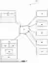


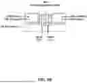


Sources:
- United States Patent and Trademark Office - verify current appl. status at the USPTO↗
Recent applications in this class:
- » 20260145219 2026-05-28
HOT-STAMPING ALUMINUM FORMATION PROCESS - » 20260145218 2026-05-28
HOT AIR THERMOFORMING OF ALUMINUM SHEETMETAL CHASSIS WITH 3D TEXTURING - » 20260124660 2026-05-07
PLATED STEEL SHEET FOR HOT PRESS FORMING, AND METHOD OF MANUFACTURING THE SAME - » 20260097429 2026-04-09
METHOD OF MANUFACTURING HOT PRESS-FORMED MEMBER HAVING EXCELLENT PRODUCTIVITY, WELDABILITY AND FORMABILITY - » 20260097428 2026-04-09
COLD ROLLED STEEL SHEET FOR HOT-PRESS FORMING HAVING EXCELLENT SURFACE QUALITY, HOT-PRESS-FORMED MEMBER, AND METHOD FOR MANUFACTURING SAME - » 20250387821 2025-12-25
DEVICE AND METHOD FOR HOT STAMPING - » 20250332626 2025-10-30
MANUFACTURING METHOD FOR HOT-STAMPED PARTS - » 20250319509 2025-10-16
PLATED STEEL SHEETS FOR HOT PRESS FORMING HAVING EXCELLENT HYDROGEN BRITTLENESS RESISTANCE AND IMPACT RESISTANCE, HOT PRESS FORMED PARTS, AND MANUFACTURING METHODS THEREOF - » 20250222506 2025-07-10
CRACK-CONTAINING HOT-STAMPED COATED STEEL PART WITH EXCELLENT SPOT-WELDABILITY AND EXCELLENT PAINTING ADHESION - » 20250222505 2025-07-10
PRODUCTION METHOD AND DIE FOR HOT STAMPED MEMBER COMPRISING LOCAL SOFT REGION, AND HOT STAMPED MEMBER