SINGLE-MACHINE MULTI-STATION LINKAGE PRESS MACHINE
US20260175282A1
2026-06-25
19/239,849
2025-06-16
Smart Summary: A new machine can perform multiple punching tasks at once while also cleaning itself. It has a table with several bottom dies and a sliding pressure plate that holds punching heads. Each bottom die has holes that blow away dust and a sensor to detect any raised dust. This design helps keep the machine clean and prevents damage from dust buildup during continuous use. Overall, it lowers production costs and improves efficiency in manufacturing. 🚀 TL;DR
Abstract:
Disclosed is a single-machine multi-station linkage press machine, including a press machine and cleaning devices. A bearing table is configured on the press machine, a plurality of bottom dies are arranged on the bearing table, a down pressure plate is guided and slidably arranged on the bearing table, a plurality of punching heads adapted to the bottom dies are arranged on the down pressure plate, upward dust-blowing purging holes are arranged on each bottom die, and a detection unit for detecting raised dust are arranged on each bottom die. The present disclosure may perform simultaneous punching operations on multiple-station dies while automatically cleaning the die cavities and the punching heads and removing dust and particulate matter generated by metal deformation, further preventing damage to the dies caused by particle accumulation during continuous punching processes, and achieving reduced production costs and enhanced production efficiency.
Inventors:
- Bo Yang 2 🇨🇳 Jinhua, China
- Tianwei Zhang 1 🇨🇳 Jinhua, China
- Weiguo Yao 1 🇨🇳 Jinhua, China
- Guangzheng Wu 1 🇨🇳 Jinhua, China
- Chunlei Wang 1 🇨🇳 Jinhua, China
Applicant:
Interested in similar patents?
Get notified when new applications in this technology area are published.
Classification:
B21D45/003 » CPC main
Ejecting or stripping-off devices arranged in machines or tools dealt with in this subclass in punching machines or punching tools
B21D45/00 IPC
Ejecting or stripping-off devices arranged in machines or tools dealt with in this subclass
Description
CROSS-REFERENCE TO RELATED APPLICATION
This application claims priority of Chinese Patent Application No. 202411911911.X, filed on Dec. 24, 2024, the entire contents of which are incorporated herein by reference.
TECHNICAL FIELD
The present disclosure relates to the technical field of press machines, and in particular to a single-machine multi-station linkage press machine.
BACKGROUND
Press machines (including punch presses and hydraulic presses) are designed as precision-structured universal press machines, characterized by versatile applications and high production efficiency. The press machines can be extensively utilized in processes such as cutting, punching, blanking, bending, riveting, and forming. The components are processed by applying intense pressure to metal billets, inducing plastic deformation and subsequent fracture.
In the production process of battery casings, the press machines are required to perform punch forming of the battery casings. Current battery casing forming processes are performed using single-station operation on individual machines. This method is characterized by low forming efficiency and cannot meet the demands of large-scale battery casing production. Therefore, it is necessary to develop a multi-station linkage press machine.
During the battery casing production, since battery casings are products formed through metal deformation, some minute metal particles are cracked out at bending zones of the metal during punch forming, descending into the forming die cavity. Repeated accumulation of these particles causes damage to the die cavity.
SUMMARY
Press machines in current use are limited to single-station operation and lack the function for removing particulate matter accumulated within die cavities.
In response to these limitations in the related art, the present disclosure provides a single-machine multi-station linkage press machine.
To solve the above technical problems, the present disclosure employs the following technical solutions: a single-machine multi-station linkage press machine includes a press machine, a bearing table being configured on the press machine, and a plurality of bottom dies being arranged on the bearing table, in which a down pressure plate is guided and slidably arranged on the bearing table, a plurality of punching heads adapted to the bottom dies are arranged on the down pressure plate, upward dust-blowing purging holes are arranged on each bottom die, and a detection unit for detecting raised dust is arranged on each bottom die; and cleaning devices, each cleaning device including cleaning pieces for cleaning particulate matter in a die cavity of the bottom die, and moving mechanisms for driving the cleaning pieces into a punching station, in which the cleaning piece is an elastic membrane; the punching head presses downward on the elastic membrane to drive the elastic membrane into the die cavity of the bottom die; and a surface of the elastic membrane is coated with a viscous material, and the surface of the elastic membrane is abutted against the die cavity, causing the particulate matter to be adhered to the surface of the elastic membrane.
The beneficial effects reside in that the linkage press machine can perform simultaneous punching operations on multiple-station dies while automatically removing dust and particulate matter generated by metal deformation from the die cavities, further preventing damage to the dies caused by particle accumulation during continuous punching processes, thereby achieving reduced production costs and enhanced operational efficiency.
In the above solution, preferably, an annular groove is disposed on a peripheral wall of the die cavity of the bottom die, and the annular groove is connected to a dust exhaust device, thereby adsorbing the dust in the die cavity.
In the above solution, preferably, in each cleaning device, two cleaning pieces are arranged in opposing orientations, one layer is used for adhering to and removing the particulate matter in the die cavity, and the other layer is used for adhering to and removing the particulate matter from the punching head.
In the above solution, preferably, the cleaning device further includes feeding pieces and a receiving piece, with one end of each cleaning piece wound around the feeding pieces, and the other end wound around the receiving piece; and the feeding pieces and the receiving piece are located on left and right sides of the punching head.
In the above solution, preferably, the cleaning device further includes sealing pieces and an expansion mechanism, peripheral walls of the two cleaning pieces located above the die cavity are sealed by the sealing pieces, and the expansion mechanism is used for filling an interlayer between the sealed cleaning pieces with a filling material; and when expanded and deformed, upper and lower cleaning pieces are tightly attached to the punching head and the die cavity of the bottom die.
In the above solution, preferably, top contact blocks are arranged on the down pressure plate, the top contact blocks are pressed against a main body frame after the punching head moves downward into position, and the peripheral walls of the two cleaning pieces located above the die cavity are sealed by the sealing pieces under applied pressure, forming a sealed interlayer.
In the above solution, preferably, the cleaning device further includes the main body frame, punching holes for the punching head to pass through are disposed on the main body frame, and a passage cavity for the cleaning pieces to pass through is transversely disposed on the punching holes; the sealing piece includes an annular pressure ring and guide abutting rods, and the sealing piece is slidably arranged in the passage cavity through vertical guidance of the guide abutting rods; and the cleaning pieces are pressed against an upper wall of the passage cavity during upward movement, forming a sealed interlayer between the two cleaning pieces within a pressure contact range.
In the above solution, preferably, the expansion mechanism includes an inflation nozzle, the inflation nozzle is arranged on the guide abutting rod, and a head portion of the inflation nozzle enters from a side face to a middle portion between the two cleaning pieces; and when the upper and lower cleaning pieces are sealed by the sealing pieces, a front end of the inflation nozzle is located in the sealed interlayer between the two cleaning pieces.
In the above solution, preferably, an elastic sealing ring is arranged on the annular pressure ring, an elastic sealing ring is arranged on an upper wall of the passage cavity, and the two elastic sealing rings are vertically aligned with each other.
In the above solution, preferably, a sliding groove is disposed on a side face of the guide abutting rod, and the inflation nozzle is slidably arranged on the sliding groove in a vertical movement.
The present disclosure has the following beneficial effects: the single-machine multi-station linkage press machine provided by the present disclosure can perform simultaneous punching operations on multiple-station dies while automatically cleaning the die cavities and the punching heads and removing dust and particulate matter generated by metal deformation, further preventing damage to the dies caused by particle accumulation during continuous punching processes, thereby achieving reduced production costs and enhanced operational efficiency.
BRIEF DESCRIPTION OF THE DRAWINGS
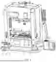
FIG. 1 is a schematic diagram of the present disclosure.
FIG. 2 is a front view of the present disclosure.
FIG. 3 is a cross-sectional view of the present disclosure.
FIG. 4 is a schematic diagram of a cleaning device of the present disclosure.
FIG. 5 is a cross-sectional view of the cleaning device of the present disclosure.
FIG. 6 is a schematic diagram of a sealing piece of the present disclosure.
FIG. 7 is a partial enlarged view of the sealing piece located in a passage cavity of the present disclosure.
DETAILED DESCRIPTION
The present disclosure is further described in detail below in combination with the accompanying drawings and specific implementations.
Embodiment 1
Referring to FIGS. 1-7,
-
- a single-machine multi-station linkage press machine includes a press machine 1, and the press machine 1 includes a bearing table 11 for fixing dies and a down pressure plate 12 for fixing punching heads of the dies. The down pressure plate 12 and the bearing table 11 are arranged in parallel, and the down pressure plate 11 is capable of being moved vertically while maintaining parallelism with the bearing table 11 during operation of the press machine 1.
A plurality of bottom dies 2 are arranged on the bearing table 11, die cavities for forming are arranged on the bottom dies 2, a plurality of purging holes 21 are evenly disposed on a bottom face of each die cavity, and the purging holes 21 can upwardly spray high-pressure air streams, thereby causing particulate matter or dust within the die cavity to be expelled upward from the die cavity. While an annular groove 22 is disposed on a peripheral wall of a middle portion of the die cavity, and the annular groove 22 is communicated with a dust absorption port of a dust absorption device, thereby generating a negative pressure suction force around the annular groove 22, causing surrounding dust or particulate matter to be drawn into the dust absorption device, further reducing the dust within the die cavity. The annular groove 22, in combined operation with the purging holes 21 at the bottom, ensures the removal of a majority of dust and particulate matter.
The annular groove 22 is arranged in a circumferential direction of the die cavity, resulting in particulate matter or dust located at the middle portion of the die cavity failing to be adsorbed. Such particulate matter or dust is blown upward onto an upper surface of the bottom die 2, dispersed into the ambient air, and either settles back into the die cavity or is carried outward, while the settled dust and particulate matter accumulate incrementally at the bottom of the die cavity over successive punching cycles, thereby causing a progressive increase in the quantity of dust and particulate matter expelled during subsequent purging cycles.
A detection unit 3 for detecting dust and particulate matter is arranged on the bottom die 2, and the detection unit 3 may be implemented as a laser dust detector. During upward emission of high-pressure air streams through the purging holes 21, this laser dust detector can detect dust within the passing air streams, thereby identifying the concentration of dust or particulate matter suspended above the bottom die 2.
When the dust or particulate matter content in the die cavity is high, the higher the dust or particulate matter content dispersed above the bottom die 2 by the air streams, the greater the value detected by detection unit 3. Therefore, by monitoring dust levels through the detection unit 3, the cleaning device 4 arranged on the press machine can be controlled to clean the die cavity once the value reaches a preset threshold.
The cleaning device 4 includes cleaning pieces 41, moving mechanisms 42, feeding pieces 43, a receiving piece 44, sealing pieces 45, an expansion mechanism 46, and a main body frame 47. The moving mechanisms include rail groups 421 and moving blocks 422, the rail groups 421 are arranged on the bearing table 11, the moving blocks 422 are guided and slidably arranged on the rail groups 421, and servo motors are arranged on the moving blocks 422, causing the moving blocks 422 to move precisely forward and backward on the rail groups 421. Moreover, the rail groups 421 and the moving blocks 422 belong to high-load-bearing type moving components, which can withstand a relatively large load-bearing capacity.
The main body frame 47 is elastically connected to the moving blocks 422 in a telescopic manner through elastic guide sliding components, with one end of the elastic guide sliding component mounted at a bottom of the main body frame 47, and the other end connected to an upper end of the moving block 422. The elastic guide sliding components can elastically contract under pressure, thereby causing the entire main body frame 47 to undergo guided downward movement when subjected to downward pressure. When the pressure is released, it can automatically return upward to its initial state.
Punching holes 47, a passage cavity 472, a material cavity 473 and a material receiving cavity 474 are disposed on the main body frame 47. The material cavity 473 and the material receiving cavity 474 are located at left and right ends of the main body frame 47, and the material cavity 473 is transversely communicated with the material receiving cavity 474 through the passage cavity 472. The punching holes 471 are vertically arranged and perpendicular to the passage cavity 472. Both the feeding piece 43 and the receiving piece 44 are roller shafts, of which two feeding pieces 43 and one receiving piece 44 are arranged. The feeding pieces 43 is damped and rotatably arranged in the material cavity 473 in a vertical movement, the receiving piece 44 is arranged in the material receiving cavity 474, a power piece is arranged on the receiving piece 44, and the power piece can rotate under the control of an electronic control unit. The cleaning piece 41 is an elastic membrane with single-sided adhesiveness. When subjected to pressure, the elastic membrane undergoes elastic deformation, thereby generating elongation and deformation bulging. Two cleaning pieces are arranged, with ends of the cleaning pieces wound around two feeding pieces 43, and the other ends jointly arranged on the receiving piece 44. Moreover, an intermediate connecting portion passes through the passage cavity 472, and the passage cavity 472 is maintained parallel to the down pressure plate 12. During downward movement of the punching head, a lower end of the punching head 121 is pressed against the cleaning pieces 41, thereby driving the cleaning pieces 41 into the die cavity.
The sealing piece 45 includes an annular pressure ring 451 and guide abutting rods 452 arranged at four corners on a lower end face of the annular pressure ring, and a guiding hole is disposed on a lower end face of the passage cavity 472. The sealing piece 45 is guided and slidably arranged in the guide hole through four guide abutting rods 452, thereby causing the annular pressure ring 451 to slidably arranged in the passage cavity 472 in a vertical movement. An elastic sealing ring 4511 is arranged on an upper surface of the annular pressure ring 451, with another elastic sealing ring 4511 further arranged on an upper end wall of the passage cavity 472 at a position corresponding to the annular pressure ring 451, and upper and lower elastic sealing rings 4511 are aligned. Four electromagnets are evenly distributed in the upper end wall of the passage cavity 472 above the annular pressure ring 451, and the electromagnets are energized to attract the annular pressure ring 451 upward, while front and back cleaning pieces 41 pass between the two elastic sealing rings 4511. When the electromagnets are energized, the area where the two cleaning pieces 41 are located in the elastic sealing rings 4511 is hermetically sealed through the two elastic sealing rings 4511.
Outer faces of the two cleaning pieces 41 are coated with viscous materials, while press-contact faces of the elastic sealing rings 4511 are further coated with viscous materials, resulting in persistent adhesion of the cleaning pieces 41 to the upper and lower elastic sealing rings 4511 following de-energization of the electromagnets. Therefore, a plurality of micro-holes are disposed on upper planes of the elastic sealing rings 4511, while oleaginous materials are stored in the elastic sealing rings 4511. When the two elastic sealing rings 4511 are abutted against each other for deformation, the area where the cleaning pieces 41 are located in the elastic sealing rings 4511 is hermetically sealed, and the stored oleaginous materials are squeezed out from interiors of the micro-holes and flow onto the surfaces of the elastic sealing rings 4511, thereby causing the contact positions between the elastic sealing rings 4511 and the cleaning pieces 41 to be not adhered.
The expansion mechanism 46 includes an inflation nozzle 461 and a docking joint 462, the inflation nozzle 461 has a C-shaped structure, a sliding groove 4521 is disposed on a guide abutting rod 452, and a C-shaped lower end of the inflation nozzle 461 is guided and slidably arranged in the sliding groove 4521, and is connected to one end of a flexible pipeline arranged in the guide abutting rod 452. An abutting hole is disposed at a lower end of the guide abutting rod 452, the other end of the flexible pipeline is communicated with the abutting hole, and the docking joint 462 is arranged on an upper end face of the bottom die 2.
Top contact blocks 122 are arranged on the down pressure plate 12, and the top contact blocks 122 are pressed against the main body frame 47 after the punching head 121 moves downward into position. At this time, the abutting hole at the lower end of the guide abutting rod 452 is inserted into the docking joint 462 on the bottom die 2, thereby realizing the supply of compressed air, and causing the inflation nozzle 461 to eject the compressed air.
The inflation nozzle 461 features a C-shaped upper end with a flattened profile, and enters a middle position of the cleaning pieces 41 form side faces of the cleaning pieces, with one cleaning piece 41 passing above the inflation nozzle 461 and the other passing beneath the inflation nozzle 461. When the down pressure plate 12 begins to move downward, the electromagnets are energized to attract the annular pressure ring 451 upward, and the area where the two cleaning pieces 41 are located in the elastic sealing rings 4511 is hermetically sealed through the two elastic sealing rings 4511, and the inflation nozzle 461 is further located between the two elastic sealing rings 4511. As the down pressure plate 12 continues its downward movement, the punching head 121 is in contact with the cleaning pieces 41, causing the cleaning pieces 41 on the contact position to be circumferentially compressed. With the sustained downward travel of the punching head 121, the cleaning pieces 41 are elastically deformed while being drawn into the die cavity in conjunction with the punching head 121.
After the down pressure plate 12 moves downward into position, the abutting hole at the lower end of the guide abutting rod 452 is inserted into the docking joint 462 on the bottom die 2 at this time, thereby realizing the supply of compressed air, and causing the inflation nozzle 461 to eject the compressed air. Furthermore, the two cleaning pieces 41 expand under the action of compressed air supplied to the middle space, causing the upper cleaning piece 41 to adhere tightly to the punching head 121 and the lower cleaning piece 41 to adhere tightly to an inner wall of the die cavity. The viscous materials on the surfaces of the cleaning pieces 41 can trap dust or particulate matter on the punching head 121 and the die cavity.
An operating principle or a method of application is as follows.
The down pressure plate 12 moves downward, while driving the multi-station punching heads to perform punch forming operations.
After each forming cycle, the purging holes 21 at the bottom of the die cavities can eject high-pressure air streams upward, and the annular grooves 22 generate negative pressure suction on the high-speed air streams to entrain dust. However, a portion of the dust particles that are not fully removed may settle back into the die cavities. Following repeated punching operations, dust and particulate matter accumulate on the bottom faces of the die cavities, causing a progressive increase in the quantity of dust and particulate matter expelled during subsequent purging cycles. With elevated dust or particulate matter content dispersed above the bottom dies 2 by the air streams, the detection units 3 can monitor dust levels. Upon reaching a preset value, the cleaning devices 4 arranged on the press machine are controlled to execute cleaning operations on the die cavities.
The moving blocks 422 are controlled to move, positioning the main body frames 47 beneath the punching heads 121. When the down pressure plate 12 begins to move downward, the electromagnets are energized to attract the annular pressure rings 451 upward, and the areas where the cleaning pieces 41 are located in the elastic sealing rings 4511 are hermetically sealed through the elastic sealing rings 4511, and the inflation nozzles 461 are further located between the elastic sealing rings 4511. As the down pressure plate 12 continues its downward movement, the punching heads 121 are in contact with the cleaning pieces 41, causing the cleaning pieces 41 on the contact positions to be circumferentially compressed. With the sustained downward travel of the punching heads 121, the cleaning pieces 41 are elastically deformed while being drawn into the die cavities in conjunction with the punching heads 121.
After the down pressure plate 12 moves downward into position, the abutting hole at the lower end of the guide abutting rod 452 is inserted into the docking joint 462 on the bottom die 2 at this time, thereby realizing the supply of compressed air, and causing the inflation nozzle 461 to eject the compressed air. Furthermore, the two cleaning pieces 41 expand under the action of compressed air supplied to the middle space, causing the upper cleaning piece 41 to adhere tightly to the punching head 121 and the lower cleaning piece 41 to adhere tightly to an inner wall of the die cavity. The viscous materials on the surfaces of the cleaning pieces 41 can trap dust or particulate matter on the punching head 121 and the die cavity.
After staying for a period of time, the down pressure plate 12 starts to restore upward. During this restoring phase, the abutting holes disengage from the docking joints 462, thereby cutting off the compressed air supply. Moreover, the cleaning pieces 41 return to a closely adhered configuration under inherent elastic forces, expelling previously introduced air through the inflation nozzles 461. As the punching heads 121 completes its upward return motion, the cleaning pieces 41 restore to the initial flat state.
The punching heads 121 and the surfaces of the die cavities exhibit high surface finish, which prevents the cleaning pieces 41 from adhering to the surfaces of the punching heads 121 and the die cavities. When subjected to inherent elastic restoring forces, the cleaning pieces 41 achieve self-release. However, dust or particulate matter remain adhered to the surfaces of cleaning pieces 41.
Upon the down pressure plate 12 returning to its initial height, the electromagnets are powered off, causing the cleaning pieces 41 to separate. The receiving pieces 44 are started to rotate, winding the used portion of the cleaning pieces 41 around the receiving pieces 44, while pulling the two feeding pieces 43 to rotate and advance the unused portion into the position beneath the punching heads 121, getting ready for the next cleaning. The moving blocks 422 move backward, driving the main body frames 47 move away from beneath the punching heads 121, thereby completing a full cleaning cycle.
Embodiment 2
Referring to FIGS. 1-7, the difference from Embodiment 1 lies in the operation timing of receiving piece 44, while all other configurations remain identical.
In this embodiment, after the cleaning pieces 41 complete the die cavity cleaning process, this device resets to its initial position, with the receiving piece 44 remaining stationary. As a result, the used portion of the cleaning pieces 41 remains positioned within the punching holes. When the air streams are ejected upward from the purging holes 21, a portion of the blown dust and particulate matter is carried by the air streams, causing impacts on the used cleaning pieces 41, and leading to continuous accumulation of adhered dust and particulate matter.
When the detection unit 3 monitors elevated dust contents, the receiving piece 44 is stared to work, winding the used portion around the receiving piece 44, while advancing the unused portion into the punching holes, further ensuring that the cleaning elements for cleaning the die cavity and the punching head are unused, thereby preserving the adhesive integrity of the surfaces of the cleaning pieces 31.
It is to be noted that the above embodiments are only used for stating the technical solutions of the present disclosure, but not limitation. Although the present disclosure is described in detail by reference to the foregoing embodiments, for those ordinary skilled in the art, it is to be understood that the technical solutions described in the above embodiments may still be modified, or some or all of the technical features may be equivalently replaced. However, these modifications or substitutions do not deviate the essence of the corresponding technical solutions from the scope of the technical solutions of each embodiment of the present disclosure.
Claims
1. A single-machine multi-station linkage press machine, comprising a press machine (1), a bearing table (11) being configured on the press machine (1), and a plurality of bottom dies (2) being arranged on the bearing table (11), wherein:
a down pressure plate (12) is guided and slidably arranged on the bearing table (11), a plurality of punching heads (121) adapted to the bottom dies (2) is arranged on the down pressure plate (12), upward dust-blowing purging holes (21) is arranged on each bottom die (2), and a detection unit (3) for detecting raised dust is arranged on each bottom die (2); and
cleaning devices (4), each cleaning device (4) comprising cleaning pieces (41) for cleaning particulate matter in a die cavity of the bottom die (2), and moving mechanisms (42) for driving the cleaning pieces (41) into a punching station, wherein:
the cleaning piece (41) is an elastic membrane; the punching head (121) presses downward on the elastic membrane to drive the elastic membrane into the die cavity of the bottom die (2); and a surface of the elastic membrane is coated with a viscous material, and the surface of the elastic membrane is abutted against the die cavity, causing the particulate matter to be adhered to the surface of the elastic membrane.
2. The single-machine multi-station linkage press machine according to claim 1, wherein an annular groove (22) is disposed on a peripheral wall of the die cavity of the bottom die (2), and the annular groove (22) is connected to a dust absorption device, adsorbing the dust in the die cavity.
3. The single-machine multi-station linkage press machine according to claim 1, wherein in each cleaning device (4), two cleaning pieces (41) are arranged in opposing orientations, one layer is used for adhering to and removing the particulate matter in the die cavity, and the other layer is used for adhering to and removing the particulate matter from the punching head (121).
4. The single-machine multi-station linkage press machine according to claim 3, wherein the cleaning device (4) further comprises feeding pieces (43) and a receiving piece (44), with one end of each cleaning piece (41) wound around the feeding pieces (43), and the other end wound around the receiving piece and the feeding pieces (43) and the receiving piece are located on left and right sides of the punching head (121).
5. The single-machine multi-station linkage press machine according to claim 3, wherein the cleaning device (4) further comprises sealing pieces (45) and an expansion mechanism (46), peripheral walls of the two cleaning pieces (41) located above the die cavity are sealed by the sealing pieces (45), and the expansion mechanism (46) is used for filling an interlayer between the sealed cleaning pieces (41) with a filling material; and when expanded and deformed, upper and lower cleaning pieces (41) are tightly attached to the punching head (121) and the die cavity of the bottom die (2).
6. The single-machine multi-station linkage press machine according to claim 5, wherein top contact blocks (122) are arranged on the down pressure plate (12), the top contact blocks (122) are pressed against a main body frame (47) after the punching head (121) moves downward into position, and the peripheral walls of the two cleaning pieces (41) located above the die cavity are sealed by the sealing pieces (45) under applied pressure, forming a sealed interlayer.
7. The single-machine multi-station linkage press machine according to claim 5, wherein the cleaning device (4) further comprises the main body frame (47), punching holes (471) for the punching head (121) to pass through are disposed on the main body frame (47), and a passage cavity (472) for the cleaning pieces (41) to pass through is transversely disposed on the punching holes (471); the sealing piece (45) comprises an annular pressure ring (451) and guide abutting rods (452), and the sealing piece (45) is slidably arranged in the passage cavity (472) through vertical guidance of the guide abutting rods (452); and the cleaning pieces (41) are pressed against an upper wall of the passage cavity (472) during upward movement, forming a sealed interlayer between the two cleaning pieces (41) within a pressure contact range.
8. The single-machine multi-station linkage press machine according to claim 7, wherein the expansion mechanism (46) comprises an inflation nozzle (461), the inflation nozzle (461) is arranged on the guide abutting rod (452), and a head portion of the inflation nozzle (461) enters from a side face to a middle portion between the two cleaning pieces (41); and when the upper and lower cleaning pieces (41) are sealed by the sealing pieces (45), a front end of the inflation nozzle (461) is located in the sealed interlayer between the two cleaning pieces (41).
9. The single-machine multi-station linkage press machine according to claim 7, wherein an elastic sealing ring (4511) is arranged on the annular pressure ring (451), an elastic sealing ring (4511) is arranged on an upper wall of the passage cavity (472), and the two elastic sealing rings (4511) are vertically aligned with each other.
10. The single-machine multi-station linkage press machine according to claim 8, wherein a sliding groove (4521) is disposed on a side face of the guide abutting rod (452), and the inflation nozzle (451) is slidably arranged on the sliding groove (4521) in a vertical movement.
Images & Drawings included:


Sources:
- United States Patent and Trademark Office - verify current appl. status at the USPTO↗
Recent applications in this class:
- » 20260102815 2026-04-16
SYSTEMS AND METHODS FOR A HYDRAULIC TOOL - » 20220305545 2022-09-29
STRIPPER UNIT - » 20160325338 2016-11-10
Method for Creating Through-Passages in a Metal Body by Means of High-Speed Impact Cutting - » 20150306653 2015-10-29
Method for removing a workpiece part and machine tool - » 20150068375 2015-03-12
Method and device for precision cutting of workpieces in a press - » 20150053059 2015-02-26
Device and method for transferring workpieces into and out of a tool - » 20110079122 2011-04-07
Device and method for manufacturing work - » 20090035117 2009-02-05
Removing a processed part - » 20090010731 2009-01-08
Workpiece part discharge system - » 20080016934 2008-01-24
Method and device for the production of stamped parts