MULTI-STATION DEVICE FOR PRODUCING AND WELDING PRESTRESSED POSITIONING MESH OF BOX GIRDER
US20260175286A1
2026-06-25
19/413,474
2025-12-09
Smart Summary: A device is designed to create and weld a special mesh used in box girders. It starts by straightening and cutting steel bars into the right sizes. Then, these bars are moved along different conveyors for long and short pieces. The long bars can be bent if needed before they are assembled together with the short bars. Finally, everything is welded together and then unloaded for use. 🚀 TL;DR
Abstract:
A multi-station device for producing and welding prestressed positioning mesh of box girder, including a straightener, a load conveyor, a long bar conveyor, a short bar conveyor, an assembly conveyor, a bender, an assembly and carry mechanism, a weld mechanism, and an unload mechanism, wherein steel bar raw materials are straightened and cut by the straightener, an outlet of the straightener is connected to an inlet of the load conveyor, long bars and short bars after straightening and cutting are sent to the load conveyor and then transported to the long bar conveyor and the short bar conveyor, respectively, the long bars are sent to the bender for bending or without bending, the long bars and the short bars pass through the assembly conveyor, the assembly and carry mechanism and the weld mechanism in sequence to complete assembly and weld treatment, and are unloaded by the unload mechanism.
Inventors:
- Xiangcai Fu 1 🇨🇳 Anhui Province, China
- Zhendong Zhang 1 🇨🇳 Anhui Province, China
- Xiang Shen 1 🇨🇳 Anhui Province, China
- Tao Tang 1 🇨🇳 Anhui Province, China
- Jiangming Mao 1 🇨🇳 Anhui Province, China
- Hehuan Wang 1 🇨🇳 Anhui Province, China
- Lianka Zhang 1 🇨🇳 Anhui Province, China
- Xiguo Zhao 1 🇨🇳 Anhui Province, China
Applicant:
Interested in similar patents?
Get notified when new applications in this technology area are published.
Classification:
B21F15/08 » CPC main
Connecting wire to wire or other metallic material or objects; Connecting parts by means of wire wire with wire with additional connecting elements or material making use of soldering or welding
B21F1/026 » CPC further
Bending wire other than coiling; Straightening wire; Straightening Straightening and cutting
B21F11/00 » CPC further
Cutting wire
B21F23/00 » CPC further
Feeding wire in wire-working machines or apparatus
B21F1/02 IPC
Bending wire other than coiling; Straightening wire Straightening
Description
CROSS-REFERENCE TO RELATED APPLICATIONS
This application claims the priority and benefit of Chinese patent application No. 202411877863.7, filed on Dec. 19, 2024. The entirety of Chinese patent application No. 202411877863.7 is hereby incorporated by reference herein and made a part of this specification.
TECHNICAL FIELD
This disclosure relates to the technical field of steel mesh production, specifically to a multi-station device for producing and welding prestressed positioning mesh of box girder.
BACKGROUND ART
There is currently no production line for small box girders in the existing technical solutions. In addition, the existing production methods are not fully automated, resulting in low production efficiency and high costs. Therefore, it is necessary to provide a fully automated small box girder production line to achieve fully automated welding production of small box girders and improve production efficiency.
SUMMARY
This disclosure provides a multi-station device for producing and welding prestressed positioning mesh of box girder to overcome the problems existing in the exist technology.
In order to achieve the above-mentioned purpose of the disclosure, a multi-station device for producing and welding prestressed positioning mesh of box girder is provided, which includes a straightener, a load conveyor, a long bar conveyor, a short bar conveyor, an assembly conveyor, a bender, an assembly and carry mechanism, a weld mechanism, and an unload mechanism, wherein steel bar raw materials are straightened and cut by the straightener, an outlet of the straightener is connected to an inlet of the load conveyor, long bars and short bars after straightening and cutting are sent to the load conveyor and then transported to the long bar conveyor and the short bar conveyor, respectively, the long bars are sent to the bender for bending or without bending, the long bars and the short bars pass through the assembly conveyor, the assembly and carry mechanism and the weld mechanism in sequence to complete assembly and weld treatment, and are unloaded by the unload mechanism, wherein a short bar push module is arranged on one side of the load conveyor, the short bar push module includes a first two-stage cylinder assembly and a stop assembly, wherein the first two-stage cylinder assembly includes a first two-stage cylinder, a first cylinder support frame for fixing the first two-stage cylinder, and a first push plate mounted at an end of the first two-stage cylinder, in an initial state, the first two-stage cylinder is located in middle of an installation end of the first cylinder support frame, the short bars can be pushed in different directions by extending or retracting two cylinders of the first two-stage cylinder, respectively, wherein the stop assembly includes a sensor, a stop plate, and a stop drive mechanism, when the sensor detects the short bar, the stop drive mechanism lowers the entire stop assembly, so that the stop plate prevents the short bar from moving forward, and then the first two-stage cylinder pushes the short bar to load; when the sensor detects the long bar, the stop drive mechanism raises the entire stop assembly, so that the stop plate rises, the long bar continue to be conveyed forward with the load conveyor.
In one aspect of the disclosure, the load conveyor includes a load support, a load conveyor chain track and a load drive mechanism are provided on the load support, a power output of the load drive mechanism meshes with the load conveyor chain track, the load drive mechanism drives the load conveyor chain track to move along a conveying direction. A guide trough is provided on the load conveyor chain track, and a drop frame is provided above the guide trough, the drop frame is connected to a hydraulic cylinder at an end of the straightener through a connection plate, a cutter head is also provided at the end of the straightener, the hydraulic cylinder drives the cutter head to move, and the steel bar raw materials cut by the cutter head fall into the guide trough through the drop frame for conveying.
In one aspect of the disclosure, the short bar conveyor includes a first short bar conveyor line and a second short bar conveyor line, and both the first short bar conveyor line and the second short bar conveyor line are chain plate lines composed of a plurality of chain plates arranged in sequence, the first short bar conveyor line is provided with a plurality of short bar support seats for receiving the short bar, two ends of each chain plate are respectively provided with one of the short bar support seats, each of the short bar support seats is provided with an installation groove that matches the short bar, and an end of the short bar being conveyed is placed in the installation groove. A mechanical limit assembly is respectively mounted on each side of a load inlet of the first short bar conveyor line, and a bottom of the mechanical limit assembly is mounted on the load support.
In one aspect of the disclosure, the assembly conveyor includes a first assembly chain and a second assembly chain, the first assembly chain is arranged inside the first short bar conveyor line and the second assembly chain is arranged inside the second short bar conveyor line. The first assembly chain is provided with two identical pallet assemblies, each of the pallet assemblies is composed of a plurality of independently arranged pallets, and the pallets move on the first assembly chain.
In one aspect of the disclosure, each of the pallet assemblies includes a motor reducer, a gear connected to an output end of the motor reducer, a pallet body, two long bar limits and a short bar limit, the motor reducer, the two long bar limits and the short bar limit are all mounted on the pallet body, the short bar limit is provided between the two long bar limits, the gear is drivingly connected to a rack on the first assembly chain.
In one aspect of the disclosure, a slide plate is provided at a bottom of the pallet body, the slide plate slips fit with a slide rail on the first assembly chain, and a buckle is provided on the long bar limit, the buckle is composed of an electric push rod and a connection rod, a first end of the electric push rod is connected to the slide plate and a second end of the electric push rod is connected to the connection rod, one end of the connection rod is configured to limit the long bar.
In one aspect of the disclosure, the assembly and carry mechanism includes a short bar carrying module, the short bar carrying module is provided with a short bar carrying bracket and a plurality of short bar carrying grippers, the plurality of short bar carrying grippers are mounted on the short bar carrying bracket.
In one aspect of the disclosure, the long bar conveyor includes a first long bar transfer module and a second long bar transfer module, the first long bar transfer module and the second long bar transfer module have a same structure, both of the first long bar transfer module and the second long bar transfer module include a first transfer line and a second transfer line arranged sequentially along the conveying direction of the long bar in the load conveyor.
In one aspect of the disclosure, the long bar conveyor includes a long bar pushing module, and the long bar pushing module includes a second two-stage cylinder assembly. The second two-stage cylinder assembly includes a second two-stage cylinder, a second cylinder support frame for fixing the second two-stage cylinder, and a second push plate mounted at an end of the second two-stage cylinder, in an initial state, the second two-stage cylinder is located in middle of an installation end of the second cylinder support frame, the long bars can be pushed in different directions by extending or retracting two cylinders of the second two-stage cylinder, respectively.
In one aspect of the disclosure, the first transfer line includes a chain plate drive mechanism, a lift module, a drive chain plate, a plurality of installation seats, a plurality of first rollers, a first transfer bracket, and a first roller drive mechanism, the first roller drive mechanism and the lift module are both mounted at a bottom of a lift bracket, the lift bracket is mounted below the first transfer bracket, the plurality of installation seats are arranged above the first transfer bracket, the plurality of installation seats are spaced apart, the drive chain plate or the first roller is provided between two adjacent installation seats, the drive chain plate and the second roller are arranged alternately, the chain plate drive mechanism is mounted on one side of the installation seat.
In one aspect of the disclosure, the lift module includes the lift bracket, a lift mechanism, and a lift base plate, the lift base plate is mounted above the lift bracket, a lift slide rail is provided on one side of the lift bracket, a lift slider is slidably mounted on the lift slide rail, the lift slider is connected to a first end of a lift connection plate, and a second end of the lift connection plate is connected to a bottom surface of the lift base plate, the lift mechanism is also mounted on the lift bracket, an upper end of the lift mechanism is connected to the bottom surface of the lift base plate, in a non-lift state, the upper end of the lift bracket is non in contact with the lift base plate.
In one aspect of the disclosure, the second transfer line includes a second transfer bracket, a plurality of second rollers, and a second roller drive mechanism, a height of the second transfer bracket is higher than a height of the first transfer bracket, the plurality of second rollers are mounted above the second transfer bracket, the second roller drive mechanism is mounted at a bottom of the second transfer bracket, and a power output of the second roller drive mechanism is connected to each second roller through a chain.
In one aspect of the disclosure, the bender includes a bend bracket, a bend platform, and a position plate, wherein the bend platform is mounted on the bend bracket, a bend drive mechanism is also mounted at a bottom of the bend bracket, and a power output of the bend drive mechanism is connected to the position plate.
In one aspect of the disclosure, a bottom of the bend platform is provided with two cylinder structures, and two bend movable plates and a bend fixed plate are provided above the bend platform, the bend fixed plate is located between the two bend movable plates, and the two cylinder structures are respectively located at both ends of the bend platform, the bend movable plates are pushed to a position of the bend fixed plate in middle of the bend platform through the two cylinder structures.
In one aspect of the disclosure, the assembly and carry mechanism further includes a long bar carrying module, wherein the long bar carrying module includes a long bar carrying support frame, a synchronous belt, a long bar carrying drive mechanism, and a long bar carrying assembly, the long bar carrying drive mechanism is mounted on the long bar carrying support frame, a power output of the long bar carrying drive mechanism is connected to a synchronization assembly, the long bar carrying assembly is mounted on the synchronous belt, and the synchronous belt is sleeved on the synchronization assembly, the long bar carrying drive mechanism drives the synchronization assembly to rotate, the synchronization assembly drives the synchronous belt to rotate, and the synchronous belt drives the long bar carrying assembly to move.
In one aspect of the disclosure, the assembly and carry mechanism further includes a long bar carrying module, wherein the unload mechanism includes an unload and carry module and an unload platform, the unload and carry module includes an unload and carry bracket and an unload and carry gripper, the unload and carry gripper is mounted on the unload and carry bracket, a product gripped by the unload and carry gripper is carried to the unload platform.
Compared with the existing technology, the beneficial effects of the disclosure are that:
(1) The device of the disclosure enables the full-automatic small box girder welding production through providing the straightener, the load conveyor, the long bar conveyor, the short bar conveyor, the assembly conveyor, a bender, the assembly and carry mechanism, the weld mechanism and the unload mechanism. The production efficiency is improved, and it is suitable for welding steel mesh pieces with different sizes.
(2) According to the disclosure, the accuracy of positioning and conveying is improved through the drop frame arranged on the load conveyor which limits the movement of long or short bars conveyed on the load conveyor chain track. In addition, a guide trough structure is provided on the upper end face of the load conveyor chain track. The spacing of this guide trough structure gradually decreases from the end closer to the straightener to the end farther away from the straightener. This means the spacing at the inlet is greater than the spacing at the outlet of the steel bars. This facilitates both the entry of the steel bars and the delivery of them from the designated outlet, allowing for more accurate transmission to the next workstation's conveyor line.
(3) According to the disclosure, a mechanical limit assembly is respectively mounted on each side of a load inlet of the first short bar conveyor line, and a bottom of the mechanical limit assembly is mounted on the load support. The distance between the two mechanical limit assemblies is not less than the length of the short bar. The mechanical limit assemblies are arranged to facilitate the positioning of the position direction of the short bar transportation and reduce the error of the short bar transportation and placement position.
BRIEF DESCRIPTION OF THE DRAWINGS
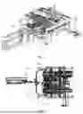
FIG. 1 is a stereoscopic schematic diagram of the overall structure of the present disclosure.
FIG. 2 is a top view of FIG. 1.
FIG. 3 is a partial structural schematic diagram of the present disclosure with the straightener omitted.
FIG. 4 is a partial structural schematic diagram of the load conveyor of the present disclosure with the guide trough omitted.
FIG. 5 is a partial top view of the load conveyor.
FIG. 6 is a partial structural schematic diagram of the short bar push module of the present disclosure.
FIG. 7 is a partial structural schematic diagram of the short bar push module of the present disclosure from another angle.
FIG. 8 is a schematic structural diagram of the first two-stage cylinder assembly of the present disclosure.
FIG. 9 is a schematic structural diagram of the first assembly chain of the present disclosure.
FIG. 10 is an enlarged structural schematic diagram of the pallet assembly in FIG. 9 of the present disclosure.
FIG. 11 is a schematic structural diagram of the first assembly chain of the present disclosure without mounting the pallet assembly.
FIG. 12 is a perspective view of the pallet assembly of the present disclosure.
FIG. 13 is a schematic structural diagram of the pallet assembly without the upper end of the pallet body.
FIG. 14 is a side view of FIG. 12 of the present disclosure.
FIG. 15 is a structural schematic diagram of the short bar carrying module of the present disclosure.
FIG. 16 is a partial structural schematic diagram of the short bar carrying bracket in FIG. 15.
FIG. 17 is a partial structural schematic diagram of the short bar carrying gripper in FIG. 15.
FIG. 18 is a schematic diagram of the carrying state of the short bar carrying module in this disclosure.
FIG. 19 is a side view of the present disclosure including the short bar carrying module.
FIG. 20 is a partial structural schematic diagram of the long bar conveyor in the present disclosure.
FIG. 21 is a schematic structural diagram of the second two-stage cylinder assembly of the present disclosure.
FIG. 22 is a partial structural diagram of FIG. 20 according to the present disclosure.
FIG. 23 is a front view of FIG. 22 of the present disclosure.
FIG. 24 is a partial structural schematic diagram of the first transfer line of the present disclosure.
FIG. 25 is a front view of FIG. 24.
FIG. 26 is a schematic structural diagram of the bend structure of the present disclosure bending the steel bar.
FIG. 27 is a side view of FIG. 26.
FIG. 28 is a front view of FIG. 26.
FIG. 29 is a schematic structural diagram of the position of the long bar carrying module according to the present disclosure.
FIG. 30 is a schematic structural diagram of the long bar carrying module of the present disclosure.
FIG. 31 is a schematic structural diagram of the long bar carrying gripper in FIG. 30.
FIG. 32 is a top view of FIG. 31.
FIG. 33 is a schematic structural diagram of the weld mechanism of the present disclosure.
FIG. 34 is a partial schematic structural diagram of the weld mechanism.
FIG. 35 is a schematic structural diagram of the weld assembly.
FIG. 36 is a schematic structural diagram of the unload mechanism.
FIG. 37 is a schematic structural diagram of the unload and carry gripper in FIG. 36.
FIG. 38 is a schematic structural diagram of the unload platform of the present disclosure.
Reference numerals: 1. straightener; 2. load conveyor; 201. load support; 202. load conveyor chain track; 203. load drive mechanism; 204. drop frame; 205. guide trough; 3. long bar conveyor; 301. first long bar transfer module; 302. second long bar transfer module; 303. first transfer line; 304. second transfer line; 305. second two-stage cylinder; 306. second cylinder support frame; 307. second push plate; 4. short bar conveyor; 401. first short bar conveyor line; 402. second short bar conveyor line; 403. short bar support seat; 404. mechanical limit assembly; 405. first two-stage cylinder; 406. first cylinder support frame; 407. first push plate; 408. stop assembly; 409. stop plate; 410. stop drive mechanism; 411. chain plate drive mechanism; 412. drive chain plate; 413. installation seat; 414. first roller; 415. first transfer bracket; 416. first roller drive mechanism; 417. lift bracket; 418. lift mechanism; 419. lift base plate; 420. second transfer bracket; 421. second roller; 422. second roller drive mechanism; 423. short bar carrying module; 424. lift slide rail; 425. lift slider; 426. lift connection plate; 5. assembly conveyor; 501. first assembly chain; 502. second assembly chain; 503. long bar limit; 504. short bar limit; 505. buckle; 506. electric push rod; 507. connection rod; 508. motor reducer; 509. gear; 510. rack; 511. pallet body; 512. slide plate; 513. slide rail; 514. laser rangefinder; 515. photoelectric switch; 516. laser sensor; 517. proximity switch sensing plate; 518. short bar carrying bracket; 519. short bar carrying gripper; 520. pallet assembly; 6. bender; 601. bend bracket; 602. bend platform; 603. position plate; 604. bend movable plate; 605. bend fixed plate; 606. pressure plate; 607. bend drive mechanism; 608. cylinder structure; 7. assembly and carry mechanism; 701. long bar carrying support frame; 702. synchronous belt; 703. long bar carrying drive mechanism; 704. synchronization assembly; 705. long bar carrying bracket; 706. long bar carrying gripper; 8. weld mechanism; 801. weld bracket; 802. weld assembly; 803. synchronous motor; 804. weld gun; 805. weld wire reel; 9. unload mechanism; 901. unload and carry bracket; 902. unload and carry gripper; 903. unload platform.
DETAILED DESCRIPTION
The present disclosure is further described and explained with the accompanying drawings and specific embodiments. The technical features of each embodiment in this disclosure can be combined accordingly, provided that there is no conflict between them.
To make the above-mentioned objects, features and advantages of the present disclosure more apparent and understandable, the specific embodiments of the present disclosure will be described in detail below with reference to the accompanying drawings. Numerous specific details are set forth in the following description in order to provide a full understanding of the disclosure.
However, the present disclosure can be implemented in many other ways different from those described herein, and those skilled in the art can make similar modifications without departing from the spirit of the disclosure. Therefore, the present disclosure is not limited to the specific embodiments disclosed below. The technical features in the various embodiments of the present disclosure can be combined accordingly without conflict with each other.
In the description of this disclosure, it should be understood that when an element is considered to be “connected” to another element, it can be a direct connection to the other element or an indirect connection, i.e., there is an intermediate element. Conversely, when an element is connected to another element “directly,” there are no intermediate elements.
In the description of this disclosure, it should be understood that the terms “first” and “second” are used only for descriptive purposes and should not be construed as indicating or implying relative importance or implicitly specifying the number of technical features indicated. Therefore, features defined as “first” or “second” may explicitly or implicitly include at least one of those features.
EXAMPLES
Referring to FIGS. 1-3, the disclosure provides a multi-station device for producing and welding prestressed positioning mesh of box girder, which includes a straightener 1, a load conveyor 2, a long bar conveyor 3, a short bar conveyor 4, an assembly conveyor 5, a bender 6, an assembly and carry mechanism, a weld mechanism 8, and an unload mechanism 9. The steel bar raw material is straightened by straightener 1, and cut into the required length, which is set according to the actual situation. In this embodiment, based on the product of the small box girder, the length of the steel bars of the small box girder is classified into long bars and short bars. In particular, all long bars have the same length and all short bars have the same length. It should be noted that, the lengths of the long and short bars can be adjusted according to the actual product. The straightener 1 is existing technology and will not be described in detail here. The outlet of the straightener 1 is connected to the inlet of the load conveyor 2. After straightening and cutting, the long and short bars are conveyed to the load conveyor 2 in a mixed state and conveyed to the next station. It should be noted that, the mixed state means that the long and short bars can be conveyed alternately, a batch of short bars can be conveyed first and then a batch of long bars can be conveyed, or a batch of long bars can be conveyed first and then another batch of long bars can be conveyed. That is, there are no restrictions on the order and periodicity of conveying long and short bars. The next stations are long bar conveyor 3 and short bar conveyor 4. In particular, the long bars and short bars are sorted at the output of load conveyor 2. The sorted short bars enter short bar conveyor 4, and the long bars continue to be conveyed by load conveyor 2 until they enter long bar conveyor 3, and the conveyed long bars are conveyed to bender 6 for bending treatment or not. Then the long bars and short bars are assembled and welded by assembly conveyor 5, assembly and carry mechanism and weld mechanism 8, and finally the unload action is realized by the unload mechanism 9.
In this embodiment, the first end of the load conveyor 2 is connected to the outlet of the straightener 1 at the previous station, and the second end of the load conveyor 2 is connected to the next station. It is configured to convey the long and short bars cut by the straightener 1 to the next station. Specifically, a movable adjustable cutter head structure is arranged at the output of the straighter 1 corresponding to the inlet of the load conveyor 2. The cutter head is mounted on the hydraulic cylinder via a installation plate. The cutter head structure can move horizontally under the drive of the hydraulic cylinder at the end of the straightener 1 as needed to perform cutting operations on the steel bars at different positions. The load conveyor 2 includes a load support 201, on which a load conveyor chain track 202 and a load drive mechanism 203 are provided. The power output of the load drive mechanism 203 is engaged with the load conveyor chain track 202. By starting the load drive mechanism 203, the load conveyor chain track 202 is driven to move along the conveying direction. In particular, the load drive mechanism 203 is located on one side of the load support 201, and the load conveyor chain track 202 is located directly above the load support 201. Furthermore, a guide trough 205 is provided on the upper end face of the load conveyor chain track 202, and a drop frame 204 is provided above the guide trough 205. The drop frame 204 is connected to the hydraulic cylinder through a connection plate, that is, the drop frame 204 will move synchronously with the movement of the cutter head. It should be noted that, the cut position of the cutter head is located inside the inlet of the drop frame 204. The drop frame 204 can be composed of two steel plates, which distribute on the upper left and right sides of the load conveyor chain track 202 respectively. From top to bottom, the inlet of the drop frame 204 is smaller than the outlet of the drop frame 204. The structure and position of the drop frame 204 are provided to prevent the cut steel bars from falling outside the load conveyor chain track 202. The cut steel bars fall through the drop frame 204 into the guide trough 205. In particular, the structure of the guide trough 205 is opposite to that of the drop frame 204. The guide trough 205 far away from the load conveyor chain track 202 is the inlet. The opening of the guide trough 205 gradually decreases from large to small in the direction close to the load conveyor chain track 202. In addition, the opening of the guide trough 205 also gradually decreases from large to small from a position close to the straightener 1 to a position far away from the straightener 1. This structural design of the guide trough 205 facilitates the stable reception of the steel bars falling from the drop frame 204 and allows the steel bars to be smoothly conveyed from the head to the tail of the load conveyor chain track 202. It should be noted that the guide trough 205 can also be made of two steel plates installed on both sides of the load conveyor chain track 202. Furthermore, the load drive mechanism 203 can be selected, but is not limited to, existing conventional drive motors.
In this embodiment, the short bar conveyor 4 includes two conveyor lines symmetrically arranged on both sides of the conveyor chain track, namely the first short bar conveyor line 401 and the second short bar conveyor line 402. Both the first short bar conveyor line 401 and the second short bar conveyor line 402 extend along the conveying direction, and the first short bar conveyor line 401 and the second short bar conveyor line 402 extend gradually away from each other. The conveying structure and conveying principle of the first short bar conveyor line 401 and the second short bar conveyor line 402 are exactly the same, and the structure is roughly L-shaped. In addition, the first short bar conveyor line 401 and the second short bar conveyor line 402 are preferably chain plate lines composed of a plurality of chain plates arranged in sequence. The conveying process of the first short bar conveyor line 401 is described in detail here, while the conveying process of the second short bar conveyor line 402 is not repeated. The first short bar conveyor line 401 is provided with a short bar support seat 403 for receiving the short bar. Two ends of each chain plate are respectively provided with one short bar support seat 403. The stability of short bar transportation or placement can be effectively improved. Specifically, the short bar support seat 403 is provided with an installation groove that matches the thickness of the short bar. The end of the short bar during transport is placed in the installation groove and transported with the movement of the chain plate line. It should be noted that at least one short bar can be placed on each chain plate for transport. Furthermore, referring to FIGS. 6 and 7, a mechanical limit assembly 404 is respectively mounted on each side of a load inlet of the first short bar conveyor line 401, and a bottom of the mechanical limit assembly 404 is mounted on the load support 201. The distance between the two mechanical limit assemblies 404 is not less than the length of the short bar. The mechanical limit assemblies 404 are arranged to facilitate the positioning of the position direction of the short bar transportation and reduce the error of the short bar transportation and placement position.
Specifically, as shown in FIGS. 6-8, a short bar push module is also provided on one side of the load conveyor 2. The short bar push module is configured to transport the short bars conveyed from the load conveyor 2 to the first short bar conveyor line 401 and the second short bar conveyor line 402. In particular, the transport method can be gripping, pushing or other methods to transport the short bars. In some embodiments, one or two short bar conveying modules can be provided. When two short bar conveying modules are provided, one short bar conveying module transports the short bar to the first short bar conveyor line 401, while the other short bar conveying module transports the short bar to the second short bar conveyor line 402. When one short bar conveying module is provided, the short bar conveying module transports the short bar to the first short bar conveyor line 401 and the second short bar conveyor line 402, and it can transport the short bar to the two conveying lines according to a certain cycle or sequence.
In this embodiment, the short bar push module includes a first two-stage cylinder 405 assembly and a stop assembly 408. The first two-stage cylinder 405 assembly includes a first two-stage cylinder 405 composed of two cylinders, a first cylinder support frame 406 for fixing the first two-stage cylinder 405, and a first push plate 407 mounted at an end of the first two-stage cylinder 405. In an initial state, the first two-stage cylinder 405 is located in middle of an installation end of the first cylinder support frame 406, the short bars are pushed in the left and right directions by extending or retracting the two cylinders in the first two-stage cylinder 405 respectively. Specifically, the first push plate 407 is an inverted U-shaped plate with its opening facing downwards. It is configured to limit the conveyed short bars in the first push plate 407. It should be noted that the opening of the first push plate 407 is adapted to the end of the guide trough 205, so as to improve the accurate effect of positioning the steel bars. In particular, the stop assembly 408 includes at least a sensor, a stop plate 409, and a stop drive mechanism 410, when the sensor detects the short bar, the stop drive mechanism 410 lowers the entire stop assembly 408, so that the stop plate 409 prevents the short bar from moving forward, and then the first two-stage cylinder 405 pushes the short bar to load; when the sensor detects the long bar, the stop drive mechanism 410 raises the entire stop assembly 408, so that the stop plate 409 rises, the long bar continue to be conveyed forward with the load conveyor 2. It should be noticed that, the stop drive mechanism 410 can be selected, but is not limited to, existing conventional drive motors.
In this embodiment, referring to FIGS. 9-14, the assembly conveyor 5 includes a first assembly chain 501 corresponding to the first short bar conveyor line 401 and a second assembly chain 502 corresponding to the second short bar conveyor line 402. The first assembly chain 501 and the second assembly chain 502 are located inside the first short bar conveyor line 401 and the second short bar conveyor line 402. That is, when short bars are conveyed, the first assembly chain 501 is configured to receive short bars from the first short bar conveyor line 401, and the second assembly chain 502 is configured to receive short bars from the second short bar conveyor line 402. In addition, when long bars are conveyed, the first assembly chain 501 and the second assembly chain 502 are also configured to receive corresponding long bars to assemble short bars. The structure and assembly principle of the first assembly chain 501 and the second assembly chain 502 are exactly the same. Here, the first assembly chain 501 is described in detail as an example, while the second assembly chain 502 will not be described in detail. Specifically, the first assembly chain 501 is provided with two identical pallet assemblies 520. Each pallet assembly 520 consists of a plurality of independently arranged pallets. The number of pallets is determined according to the number of short bars on the small box girder product. For example, if the product includes four parallel short bars, then the number of pallets is 4. The pallet can move on the first assembly chain 501, and during the movement, the spacing between the plurality of pallets on the same pallet assembly 520 can be adjusted. During the adjustment of the pallet spacing, the spacing between the short bars can be adjusted, which can be compatible with small box girders of different models and spacings. It should be specifically noted that, the pallet assembly 520 has three working positions on the first assembly chain 501 depending on the different processes. In particular, one working position is configured to receive short bars from the first short bar conveyor line 401. After receiving the short bars, the pallet assembly 520 moves to the weld working position, where it waits for the long bars to be placed. Then, the long bars and short bars are welded and fixed together. After the welding and fixing are completed, the small box girder product is initially formed. Then, it moves to the unload position for unloading. Thus, a pallet assembly 520 finally completes a small box girder product. Specifically, the first assembly chain 501 moves by means of matching transmission of gear 509 and rack 510, and a plurality of movable and independent pallet assemblies 520 are provided above the first assembly chain 501.
Specifically, referring to FIGS. 12-14, a pallet assembly 520 includes a motor reducer 508, a gear 509 connected to the output of the motor reducer 508, a pallet body 511, a long bar limit 503, and a short bar limit 504. The motor reducer 508 is a mechanical transmission device composed of a motor and a reducer. It converts the high-speed rotation of the motor into a low-speed, high-torque output through a reducer to drive various mechanical equipment and tools. The gear 509 is in transmission connection with the rack 510 on the first assembly chain 501. Two long bar limits 503 are provided, and a short bar limit 504 is provided between the two long bar limits 503. The long bar limits 503 are configured to place the long bars, and the short bar limit 504 is configured to place the short bars. Since the long bars are relatively long, in order to ensure that the limiting of the long bars is more stable, a buckle 505 structure is provided on the long bar limit 503. The buckle 505 structure serves to fix the long bars and also prevents vibration during the welding process of the long bars and short bars. Furthermore, the buckle 505 is composed of an electric push rod 506 and a connection rod 507, which realize the opening and closing action of the buckle 505. The bottom of the pallet body 511 is provided with a slide plate 512, which slides in cooperation with the slide rail 502 on the first assembly chain 501. The first end of the electric push rod 506 is connected to the slide plate 512, and the second end is connected to the connection rod 507. One end of the connection rod 507 is configured to limit the long bar. It should be noted that the spacing between the two long bars can be adjusted according to the variation of positions between long bar limits 503. Furthermore, the spacing adjustment method is as follows: the electric push rod 506 is configured for connection, both ends can slide freely. The electric push rod 506 ensures that the stroke is evenly distributed on both sides through the maximum limit on both sides when it is working. The bottom of each long bar limit 503 is fixed to two separate slide plates 512. The distance between the slide plates 512 is adjusted by the electric push rod 506. In particular, a laser rangefinder 514 and a photoelectric switch 515 may also be arranged on the slide plates 512. The laser rangefinder 514 is configured to monitor the adjustable spacing parameters between the two slide plates 512. The photoelectric switch 515 is configured to detect the long bars. The pallet body 511 is also provided with a laser sensor 516 and a proximity switch sensing plate 517. The laser sensor 516 is configured for non-contact measurement of the pallet body 511 at a distance, and the proximity switch sensing plate 517 is configured to sense and monitor the distance between adjacent pallet assemblies 520. The laser rangefinder 514, photoelectric switch 515, laser sensor 516, and proximity switch sensing plate 517 work together to achieve the effect of adjusting the spacing between the long bars. The motor reducer 508, long bar limits 503, and short bar limits 504 are all mounted on the pallet body 511.
In this embodiment, referring to FIGS. 15-19, the assembly and carry mechanism includes a short bar carrying module 423. The short bar carrying module 423 is configured to transport the short bars on the first short bar conveyor line 401 and the second short bar conveyor line 402 to the first assembly chain 501 and the second assembly chain 502 respectively. One short bar carrying module 423 can be provided or two short bar carrying modules 423 can be provided depending on the number of assembly chains. The short bar carrying module 423 is provided with a short bar carrying bracket 518 and a plurality of short bar carrying grippers 519. The short bar carrying module 423 adopts the matching transmission of the gear 509 and the rack 510 to achieve transport. Preferably, the number of short bar carrying grippers 519 is consistent with the number of pallets in a pallet assembly 520, so that the short bars on a pallet assembly 520 can be filled after one transport, thereby improving transport efficiency. Furthermore, the short bar carrying module 423 is mounted on one side of the first assembly chain 501 and/or the second assembly chain 502. The short bar carrying gripper 519 is movably mounted on the short bar carrying bracket 518. For example, the short bar carrying gripper 519 can be driven to lift and lower by an electric cylinder or a pneumatic cylinder. After the short bar carrying gripper 519 lowers to grip the short bar, it rises again to transport it to the corresponding position on the first assembly chain 501 to realize the transport action of the short bar. Referring to FIG. 17, four short bars can be moved at once and placed onto the pallet assembly 520 of the first assembly chain 501.
In this embodiment, referring to FIGS. 20-25, the long bar conveyor 3 is located inside the short bar conveyor 4. Specifically, the long bar conveyor 3 includes a long bar pushing module, a first long bar transfer module 301, and a second long bar transfer module 302. Since the short bars have already been transported to the first assembly chain 501 and the second assembly chain 502 during the conveying process of the load conveyor 2 and have entered the weld working position to wait for welding with the long bars, after the short bars are transported, the long bars continue to be transported along the load conveyor 2. Then, the long bars enter the first long bar transfer module 301 and the second long bar transfer module 302 through the long bar push module.
In particular, the first long bar transfer module 301 and the second long bar transfer module 302 have the same structure and principle. Both the first long bar transfer module 301 and the second long bar transfer module 302 include the first transfer line 303 and the second transfer line 304. It should be noted that, the description of the first long bar transfer module 301 is taken as an example. The second long bar transfer module 302 is not described repeatedly. Specifically, the first transfer line 303 and the second transfer line 304 are arranged sequentially along the conveying direction of the long bar in the load conveyor 2, and the first transfer line 303 is provided below the end of the load conveyor chain track 202 of the load conveyor 2. Further, the long bar pushing module includes a second two-stage cylinder 305 assembly. In particular, the two second two-stage cylinder 305 assemblies are arranged on both sides of the first transfer line 303, and the second two-stage cylinder 305 assembly includes a second two-stage cylinder 305 composed of two cylinders, a second cylinder support frame 306 for fixing the second two-stage cylinder 305, and a second push plate 307 mounted at the end of the second two-stage cylinder 305. It should be noted that, the pushing principle of the second two-stage cylinder 305 assembly is similar to that of the first two-stage cylinder 305 assembly. In the initial state, the second two-stage cylinder 305 is located in the middle of the installation end of the second cylinder support frame 306. The two cylinders in the second two-stage cylinder 305 extend or retract respectively to push the long bars in two directions. Specifically, the second push plate 307 is an inverted U-shaped plate with its opening facing downwards. This opening is configured to limit the transferred long bar from being located in the second push plate 307. The difference between the second push plate 307 and the first push plate 407 is the length. Because the length of the long bar is longer than that of the short bar, a longer second push plate 307 is required to limit the length of the long bar. In order to make the pushing process more stable, two second cylinder support frames 306 and two second two-stage cylinders 305 are provided. The ends of the two second two-stage cylinders 305 are connected to the same second push plate 307. The two second cylinder support frames 306 are mounted on both sides of the first transfer line 303 along the transport direction of the long bar.
In some specific embodiments, the first transfer line 303 includes a chain plate drive mechanism 411, a lift module, a drive chain plate 412, a plurality of installation seats 413, a plurality of first rollers 414, a first transfer bracket 415, and a first roller drive mechanism 416. The lift module includes a lift bracket 417, a lift mechanism 418, and a lift base plate 419. To save space, the first roller drive mechanism 416 and the lift module are both mounted at the bottom of the lift bracket 417, the lift bracket 417 is mounted below the first transfer bracket 415, a plurality of installation seats 413 are arranged above the first transfer bracket 415, with the plurality of installation seats 413 spaced apart. A drive chain plate 412 or a first roller 414 is provided between adjacent installation seats 413. The drive chain plate 412 and the second roller 421 are arranged alternately. A chain plate drive mechanism 411 is mounted on one side of the installation seat 413. The output of the chain plate drive mechanism 411 drives the drive chain plate 412 to perform the function of transferring and transporting long bars. The drive chain plate 412 can also be provided with a buckle 505 structure. Adjacent first rollers 414 are connected by a chain to ensure synchronous rolling. The chain is connected to the output of the first roller drive mechanism 416. The activation of the first roller drive mechanism 416 drives the chain to move between each roller.
Furthermore, a plurality of first rollers 414 are integrated and mounted on the same lift base plate 419. The first roller drive mechanism 416 is also mounted below the lift base plate 419. In this embodiment, the lift base plate 419 is mounted above the lift bracket 417, and a lift slide rail 424 is arranged on the side of the lift bracket 417. The lift slider 425 is slidably mounted on the lift slide rail 424. The lift slider 425 is connected to the first end of the lift connection plate 426. The second end of the lift connection plate 426 is connected to the bottom surface of the lift base plate 419. A lift mechanism 418 is also mounted on the lift bracket 417. The upper end of the lift mechanism 418 is connected to the bottom surface of the lift base plate 419. In the non-lifting state, the upper end of the lift bracket 417 is connected to the lift base plate 419 in a non-contact manner. When the lifting action is performed, the lift mechanism 418 is activated, and the lift base plate 419 is raised through the cooperation of the lift slide rail 424, the lift slider 425 and the lift connection plate 426. The first roller 414 and the first roller drive mechanism 416 mounted on the lift base plate 419 are lifted together. It should be noted that the chain plate drive mechanism 411 and the first roller drive mechanism 416 can be selected from, but are not limited to, conventional drive motors, and the lift mechanism 418 can also be any conventional lift device that can achieve the lifting effect. The corresponding existing structures will not be described in detail.
In some specific embodiments, the second transfer line 304 includes a second transfer bracket 420, a plurality of second rollers 421 and a second roller drive mechanism 422. The height of the second transfer bracket 420 is higher than the height of the first transfer bracket 415. Therefore, a lift module needs to be provided on the first transfer line 303 to achieve lifting, so that the long bar can be pushed forward smoothly. In addition, the second transfer bracket 420 also plays a transfer role to prevent excessive load. The plurality of second rollers 421 are mounted above the second transfer bracket 420, the second roller drive mechanism 422 is mounted at a bottom of the second transfer bracket 420, and a power output of the second roller drive mechanism 422 is connected to each second roller 421 through a chain to ensure synchronous rolling. Meanwhile, the second roller 421 can transport the long bar to the next station, namely the bender 6. It should be further explained that, according to the product characteristics of small box girders, since a small box girder finished product includes two long bars, the first long bar transfer module 301 and the second long bar transfer module 302 both transport the two parallel long bars to the bender 6 at one time.
In this embodiment, referring to FIGS. 26-28, the bender 6 is located at the output of the second transfer line 304. The bender 6 includes a bend bracket 601, a bend platform 602, and a position plate 603. The bend platform 602 is mounted on the bend bracket 601. Specifically, there are two bend brackets 601, and one bend platform 602 is mounted on each bend bracket 601. The first bend platform 602 is configured to receive long bars conveyed from the first long bar transfer module 301, and the second bend platform 602 is configured to receive long bars conveyed from the second long bar transfer module 302. If the product requires bending of the long bars, the bender 6 will bend the long bars. If bending is not required, the product will be temporarily placed without bending. The two pairs of long bars on the two bend platforms 602 can be used to make two finished products. Then, the long bars on the two bend platforms 602 are sent to the pallet assembly 520 on the first assembly chain 501 or the second assembly chain 502 through the long bar carrying module. One pair of long bars are stacked vertically together with the short bars on a plurality of pallets on the pallet assembly 520. A single transport by the long bar carrying module can enable two products on the first assembly chain 501 or the second assembly chain 502 to complete the initial assembly and await welding fixation. Specifically, the bottom of the bend platform 602 is provided with two cylinder structures 608, and two bend movable plates 604 and a bend fixed plate 605 are provided above the bend platform 602, the bend fixed plate 605 is located between the two bend movable plates 604, and the two cylinder structures 608 are respectively located at both ends of the bend platform 602, the bend movable plates 604 for pushing at both ends are pushed to the bend fixed plate 605 in middle of the bend platform 602 to achieve the bending effect of the long bar. It should be further explained that between each bend movable plate 604 and bend fixed plate 605 is provided with a bend angle, for example, set to an approximate S-shaped bending shape, in order to achieve the required bending effect. Furthermore, a pressure plate 606 can be mounted above the bend fixed plate 605 to fix and tighten the long bars, thereby improving bending accuracy. In particular, the bend bracket 601 is also installed with a bend drive mechanism 607 at its bottom. The power output of the bend drive mechanism 607 is connected to the position plate 603. The position plate 603 moves along the length of the bend drive mechanism 607 and is located inside the bend bracket 601. Its range of motion is limited by the bend bracket 601. The purpose of setting the position plate 603 is to push the long bar to the designated position for bending operation according to the bending position. It should be noted that when not performing a bending operation, the bend drive mechanism 607 does not need to be started. Furthermore, the bend drive mechanism 607 can be selected, but is not limited to, existing conventional drive motors, and will not be described in detail here.
In a specific embodiment, referring to FIGS. 29-32, the assembly and carry mechanism further includes a long bar carrying module. The long bar carrying module uses a synchronous belt 702 to drive the long bars to achieve the carrying effect. Specifically, the long bar carrying module is configured to transport the bent or unbent long bars on the two bend platforms 602 to the first assembly chain 501 or the second assembly chain 502 to perform corresponding welding operations with the short bars. Specifically, the long bar carrying module includes a long bar carrying support frame 701, a synchronous belt 702, a long bar carrying drive mechanism 703, and a long bar transport assembly. The long bar carrying support frame 701 is installed with the long bar carrying drive mechanism 703, and the power output of the long bar carrying drive mechanism 703 is connected to a synchronization assembly 704. The synchronization assembly 704 includes a plurality of synchronous pulleys and a synchronous rod. Each end of the synchronous rod has one synchronous pulley, with the first synchronous pulley serving as a drive pulley and the second synchronous pulley as a driven pulley. The drive pulley is driven by the power output of the long bar carrying drive mechanism 703 to move. A driven wheel is provided at a position away from the drive wheel and the driven wheel. That is, a synchronous wheel is provided at each of the four corners of the long bar carrying support frame 701. The drive wheel is connected to a driven wheel through a synchronous belt 702. The driven wheel on the synchronous rod is also connected to a driven wheel through a synchronous belt 702. The two synchronous belts 702 are arranged in parallel, and a long bar carrying assembly is provided between the two parallel belts. The movement of the synchronous belts 702 drives the long bar carrying assembly to move. In this embodiment, the long bar carrying assembly includes a long bar carrying bracket 705 and a plurality of long bar carrying grippers 706. The cooperation between the long bar carrying bracket 705 and the plurality of long bar carrying grippers 706 is achieved by a cylinder to realize the lifting action. After the long bar carrying grippers 706 lower to grip the long bar, they rise and transport it to the corresponding position of the first assembly chain 501 or the second assembly chain 502 to realize the transport action of the long bar. As shown in the figures, four long bars are grasped twice, which means there are two sets of long bar structures. Preferably, the long bar carrying gripper 706 has three pairs of fixed grippers for gripping the long bar and transporting it to the short bar. For example, three pairs of grippers are provided according to the bending situation. In particular, from top to bottom, they are the first pair of grippers, the second pair of grippers and the third pair of grippers. The first pair of grippers and the third pair of grippers are configured to grip the unbent long bar, and the second pair of grippers and the third pair of grippers are configured to grip the bent long bar.
In this embodiment, referring to FIGS. 33-35, the weld mechanism 8 is configured to move onto the first assembly chain 501 or the second assembly chain 502 to weld the long bars and short bars together. Specifically, the weld mechanism 8 includes a weld bracket 801 and a weld assembly 802. Preferably, two weld assemblies 802 are provided with identical structures.
Each weld assembly 802 includes a synchronous motor 803 and a weld wire reel 805. Each weld assembly 802 has one synchronous motor 803, which is configured to achieve the adjustment effect when weld different positions. It can be adjusted in two directions according to the model of the small box girder. The synchronous motor 803 is provided with a weld wire reel 805 that can move along the length of the synchronous motor 803. The weld wire reel 805 is provided with an electric push rod 506 or a cylinder, weld wire, weld gun 804, spring clamping structure, etc. Depending on whether it is bent, the spacing between a plurality of weld wires is adjusted by pushing the cylinder. Specifically, the weld wire is mounted on the weld gun 804 for welding. The electric push rod 506/cylinder can adjust the spacing between two weld guns 804 on the same synchronous motor 803. The spring clamping structure can prevent the steel wire from deviating. It should be noted that the weld mechanism 8 is an existing structure, and will not be described in detail here. It should be noted that the initial position of the weld mechanism 8 is arranged between the first assembly chain 501 and the second assembly chain 502.
In this embodiment, referring to FIGS. 36-38, the unload mechanism 9 is located at the end of the entire device. The unload mechanism 9 includes an unload and carry module and an unload platform 903. The unload and carry module includes an unload and carry bracket 901 and an unload and carry gripper 902. The unload and carry module can also adopt the matching transmission of the gear 509 and the rack 510 to achieve transport. Specifically, the unload and carry gripper 902 is mounted on the unload and carry bracket 901. It can be driven by an electric cylinder or a pneumatic cylinder to lift and lower the unload and carry gripper 902. After the unload and carry gripper 902 lowers to pick up the product, it rises and transports it to the unload platform 903, and then the unload operation is realized from the unload platform 903. It should be further explained that a unload conveyor module can be provided below the unload platform 903.
The unload conveyor module consists of components such as a motor, a chain, and a synchronous wheel, which facilitates the movement of the unload platform 903. The structure of the unload conveyor module is a conventional structure. The motor drives the synchronous wheel to rotate, and the chain covers the synchronous wheel for transmission. The unload platform 903 placed on the chain is moved through the chain transmission.
The overall working principle of the device is as follows: firstly, the straightener 1 straightens and cuts the steel bars into short bars and long bars. Then, the straightener 1 transports the short bars to the load conveyor 2, and the short bar conveyor 4 gradually moves the transported short bars onto the first short bar conveyor line 401 and/or the second short bar conveyor line 402. The first short bar conveyor line 401 and the second short bar conveyor line 402 transport the short bars respectively, while the straightener 1 transports the long bars to the load conveyor 2, and the long bar pushing module begins to push the long bars onto the first long bar transfer module 301 and/or the second long bar transfer module 302. The short bar carrying module 423 moves the short bars on the first short bar conveyor line 401 onto the first assembly chain 501, at the same time, moves the short bars on the second short bar conveyor line 402 onto the second assembly chain 502 and then to the weld position. The long bar pushing module pushes the long bars onto the first long bar transfer module 301 and/or the second long bar transfer module 302, and then transports them to the bender 6 for bending. A plurality of pallet assemblies 520 on the first assembly chain 501 reach the weld position, and the long bar carrying module sends the long bars on the two bend platforms 602 onto the pallet assemblies 520 of the first assembly chain 501. At the same time, two pallet assemblies 520 on the second assembly chain 502 reach the weld position, and the long bar carrying module sends the long bars on the two bend platforms 602 onto the pallet assemblies 520 of the second assembly chain 502. The weld module reaches the position above the first assembly chain 501 and begins the welding operation. After the product on the first assembly chain 501 is welded, the weld module returns. The two pallet assemblies 520 on the first assembly chain 501 reach the unload position. The unload and carry module takes away the product on the first assembly chain 501, and the pallet assembly 520 on the first assembly chain 501 returns to its original position. Simultaneously, the weld module reaches the position above the second assembly chain 502 and begins the welding operation. After the product on the second assembly chain 502 is welded, the weld module returns. The two pallet assemblies 520 on the second assembly chain 502 reach the unload position. The unload and carry module takes away the product on the second assembly chain 502, and the pallet assembly 520 on the second assembly chain 502 returns to its original position. The above steps are repeated to achieve dual-station operation of the small box girder. In addition, depending on the space arrangement, four stations can be provided, that is, there are four assembly chains, with two assembly chains are arranged on each side, to further improve work efficiency.
It should be noted that the above content is only used to illustrate the present disclosure, rather than to limit the scope of protection of the present disclosure. Simple modifications or equivalent substitutions of the present disclosure by ordinary skilled in the art do not deviate from the essence and scope of the present disclosure.
Claims
What is claimed is:1. A multi-station device for producing and welding prestressed positioning mesh of box girder, comprising a straightener, a load conveyor, a long bar conveyor, a short bar conveyor, an assembly conveyor, a bender, an assembly and carry mechanism, a weld mechanism, and an unload mechanism,
wherein steel bar raw materials are straightened and cut by the straightener, an outlet of the straightener is connected to an inlet of the load conveyor, long bars and short bars after straightening and cutting are sent to the load conveyor and then transported to the long bar conveyor and the short bar conveyor, respectively, the long bars are sent to the bender for bending or without bending, the long bars and the short bars pass through the assembly conveyor, the assembly and carry mechanism and the weld mechanism in sequence to complete assembly and weld treatment, and are unloaded by the unload mechanism,
wherein a short bar push module is arranged on one side of the load conveyor, the short bar push module comprises a first two-stage cylinder assembly and a stop assembly,
wherein the first two-stage cylinder assembly comprises a first two-stage cylinder, a first cylinder support frame for fixing the first two-stage cylinder, and a first push plate mounted at an end of the first two-stage cylinder, in an initial state, the first two-stage cylinder is located in a middle of an installation end of the first cylinder support frame, the short bars are configured to be pushed in different directions by extending or retracting two cylinders of the first two-stage cylinder, respectively,
wherein the stop assembly comprises a sensor, a stop plate, and a stop drive mechanism, when the sensor detects the short bar, the stop drive mechanism lowers an entirety of the stop assembly, so that the stop plate prevents the short bar from moving forward, and then the first two-stage cylinder pushes the short bar to load; when the sensor detects the long bar, the stop drive mechanism raises the entirety of the stop assembly, so that the stop plate rises, and the long bar continue to be conveyed forward with the load conveyor.
2. The multi-station device for producing and welding prestressed positioning mesh of box girder according to claim 1, wherein the load conveyor comprises a load support, and a load conveyor chain track and a load drive mechanism are provided on the load support,
a power output of the load drive mechanism meshes with the load conveyor chain track, and the load drive mechanism drives the load conveyor chain track to move along a conveying direction,
a guide trough is provided on the load conveyor chain track, and a drop frame is provided above the guide trough, the drop frame is connected to a hydraulic cylinder at an end of the straightener through a connection plate, a cutter head is also provided at the end of the straightener, the hydraulic cylinder drives the cutter head to move, and the steel bar raw materials cut by the cutter head fall into the guide trough through the drop frame for conveying.
3. The multi-station device for producing and welding prestressed positioning mesh of box girder according to claim 2, wherein the short bar conveyor comprises a first short bar conveyor line and a second short bar conveyor line, and both the first short bar conveyor line and the second short bar conveyor line are chain plate lines composed of a plurality of chain plates arranged in sequence,
the first short bar conveyor line is provided with a plurality of short bar support seats for receiving the short bar, two ends of each chain plate of the plurality of chain plates are respectively provided with one of the plurality of short bar support seats, each of the plurality of short bar support seats is provided with an installation groove that matches the short bar, and an end of the short bar being conveyed is placed in the installation groove,
a mechanical limit assembly is respectively mounted on each side of a load inlet of the first short bar conveyor line, and a bottom of the mechanical limit assembly is mounted on the load support.
4. The multi-station device for producing and welding prestressed positioning mesh of box girder according to claim 3, wherein the assembly conveyor comprises a first assembly chain and a second assembly chain, the first assembly chain is arranged inside the first short bar conveyor line and the second assembly chain is arranged inside the second short bar conveyor line, the first assembly chain is provided with two identical pallet assemblies, each of the two identical pallet assemblies is composed of a plurality of independently arranged pallets, and the plurality of independently arranged pallets move on the first assembly chain.
5. The multi-station device for producing and welding prestressed positioning mesh of box girder according to claim 4, wherein each of the two identical pallet assemblies comprises a motor reducer, a gear connected to an output end of the motor reducer, a pallet body, two long bar limits and a short bar limit, the motor reducer, the two long bar limits and the short bar limit are all mounted on the pallet body, the short bar limit is provided between the two long bar limits, and the gear is drivingly connected to a rack on the first assembly chain.
6. The multi-station device for producing and welding prestressed positioning mesh of box girder according to claim 5, wherein a slide plate is provided at a bottom of the pallet body, the slide plate slips fit with a slide rail on the first assembly chain, and a buckle is provided on the long bar limit, the buckle is composed of an electric push rod and a connection rod, a first end of the electric push rod is connected to the slide plate and a second end of the electric push rod is connected to the connection rod, and one end of the connection rod is configured to limit the long bar.
7. The multi-station device for producing and welding prestressed positioning mesh of box girder according to claim 1, wherein the assembly and carry mechanism comprises a short bar carrying module, the short bar carrying module is provided with a short bar carrying bracket and a plurality of short bar carrying grippers, and the plurality of short bar carrying grippers are mounted on the short bar carrying bracket.
8. The multi-station device for producing and welding prestressed positioning mesh of box girder according to claim 1, wherein the long bar conveyor comprises a first long bar transfer module and a second long bar transfer module, the first long bar transfer module and the second long bar transfer module have a same structure, both of the first long bar transfer module and the second long bar transfer module comprise a first transfer line and a second transfer line arranged sequentially along a conveying direction of the long bar in the load conveyor.
9. The multi-station device for producing and welding prestressed positioning mesh of box girder according to claim 8, wherein the long bar conveyor comprises a long bar pushing module, and the long bar pushing module comprises a second two-stage cylinder assembly,
the second two-stage cylinder assembly comprises a second two-stage cylinder, a second cylinder support frame for fixing the second two-stage cylinder, and a second push plate mounted at an end of the second two-stage cylinder, in an initial state, the second two-stage cylinder is located in a middle of an installation end of the second cylinder support frame, the long bars are configured to be pushed in different directions by extending or retracting two cylinders of the second two-stage cylinder, respectively.
10. The multi-station device for producing and welding prestressed positioning mesh of box girder according to claim 8, wherein the first transfer line comprises a chain plate drive mechanism, a lift module, a drive chain plate, a plurality of installation seats, a plurality of first rollers, a first transfer bracket, and a first roller drive mechanism, the first roller drive mechanism and the lift module are both mounted at a bottom of a lift bracket, the lift bracket is mounted below the first transfer bracket, the plurality of installation seats are arranged above the first transfer bracket, the plurality of installation seats are spaced apart, the drive chain plate or one of the plurality of first rollers is provided between two adjacent installation seats of the plurality of installation seats, the drive chain plate and the plurality of first rollers are arranged alternately, and the chain plate drive mechanism is mounted on one side of the one of the plurality of installation seats.
11. The multi-station device for producing and welding prestressed positioning mesh of box girder according to claim 10, wherein the lift module comprises the lift bracket, a lift mechanism, and a lift base plate, the lift base plate is mounted above the lift bracket, a lift slide rail is provided on one side of the lift bracket, a lift slider is slidably mounted on the lift slide rail, the lift slider is connected to a first end of a lift connection plate, and a second end of the lift connection plate is connected to a bottom surface of the lift base plate, the lift mechanism is also mounted on the lift bracket, an upper end of the lift mechanism is connected to the bottom surface of the lift base plate, in a non-lift state, an upper end of the lift bracket is non in contact with the lift base plate.
12. The multi-station device for producing and welding prestressed positioning mesh of box girder according to claim 11, wherein the second transfer line comprises a second transfer bracket, a plurality of second rollers, and a second roller drive mechanism, a height of the second transfer bracket is higher than a height of the first transfer bracket, the plurality of second rollers are mounted above the second transfer bracket, the second roller drive mechanism is mounted at a bottom of the second transfer bracket, and a power output of the second roller drive mechanism is connected to each of the plurality of second rollers through a chain.
13. The multi-station device for producing and welding prestressed positioning mesh of box girder according to claim 1, wherein the bender comprises a bend bracket, a bend platform, and a position plate, wherein the bend platform is mounted on the bend bracket, a bend drive mechanism is also mounted at a bottom of the bend bracket, and a power output of the bend drive mechanism is connected to the position plate.
14. The multi-station device for producing and welding prestressed positioning mesh of box girder according to claim 13, wherein a bottom of the bend platform is provided with two cylinder structures, and two bend movable plates and a bend fixed plate are provided above the bend platform, the bend fixed plate is located between the two bend movable plates, and the two cylinder structures are respectively located at both ends of the bend platform, and the two bend movable plates are pushed to a position of the bend fixed plate in a middle of the bend platform through the two cylinder structures.
15. The multi-station device for producing and welding prestressed positioning mesh of box girder according to claim 1, wherein the assembly and carry mechanism further comprises a long bar carrying module, wherein the long bar carrying module comprises a long bar carrying support frame, a synchronous belt, a long bar carrying drive mechanism, and a long bar carrying assembly,
the long bar carrying drive mechanism is mounted on the long bar carrying support frame, a power output of the long bar carrying drive mechanism is connected to a synchronization assembly, the long bar carrying assembly is mounted on the synchronous belt, and the synchronous belt is sleeved on the synchronization assembly,
the long bar carrying drive mechanism drives the synchronization assembly to rotate, the synchronization assembly drives the synchronous belt to rotate, and the synchronous belt drives the long bar carrying assembly to move.
16. The multi-station device for producing and welding prestressed positioning mesh of box girder according to claim 1, wherein the unload mechanism comprises an unload and carry module and an unload platform, the unload and carry module comprises an unload and carry bracket and an unload and carry gripper, the unload and carry gripper is mounted on the unload and carry bracket, a product gripped by the unload and carry gripper is carried to the unload platform.
17. The multi-station device for producing and welding prestressed positioning mesh of box girder according to claim 9, wherein the first transfer line comprises a chain plate drive mechanism, a lift module, a drive chain plate, a plurality of installation seats, a plurality of first rollers, a first transfer bracket, and a first roller drive mechanism, the first roller drive mechanism and the lift module are both mounted at a bottom of a lift bracket, the lift bracket is mounted below the first transfer bracket, the plurality of installation seats are arranged above the first transfer bracket, the plurality of installation seats are spaced apart, the drive chain plate or one of the plurality of first rollers is provided between two adjacent installation seats of the plurality of installation seats, the drive chain plate and the plurality of first rollers are arranged alternately, and the chain plate drive mechanism is mounted on one side of the one of the plurality of installation seats.
18. The multi-station device for producing and welding prestressed positioning mesh of box girder according to claim 17, wherein the lift module comprises the lift bracket, a lift mechanism, and a lift base plate, the lift base plate is mounted above the lift bracket, a lift slide rail is provided on one side of the lift bracket, a lift slider is slidably mounted on the lift slide rail, the lift slider is connected to a first end of a lift connection plate, and a second end of the lift connection plate is connected to a bottom surface of the lift base plate, the lift mechanism is also mounted on the lift bracket, an upper end of the lift mechanism is connected to the bottom surface of the lift base plate, in a non-lift state, an upper end of the lift bracket is non in contact with the lift base plate.
19. The multi-station device for producing and welding prestressed positioning mesh of box girder according to claim 18, wherein the second transfer line comprises a second transfer bracket, a plurality of second rollers, and a second roller drive mechanism, a height of the second transfer bracket is higher than a height of the first transfer bracket, the plurality of second rollers are mounted above the second transfer bracket, the second roller drive mechanism is mounted at a bottom of the second transfer bracket, and a power output of the second roller drive mechanism is connected to each of the plurality of second rollers through a chain.
Images & Drawings included:


Sources:
- United States Patent and Trademark Office - verify current appl. status at the USPTO↗
Recent applications in this class:
- » 20100093447 2010-04-15
Helically-wound cable and method - » 20090189007 2009-07-30
Method of and a device for producing parts - » 20080047133 2008-02-28
MANUFACTURING PROCESS AND END PRODUCT OF A WIRE-LIKE STRIP - » 20060143765 2006-07-06
Method for making titanium wire face guard