CONTROL METHOD, ELECTRONIC DEVICE, AND STORAGE MEDIUM FOR FLOATING BODY CAPABLE OF MOVING ON WATER
US20260175950A1
2026-06-25
19/037,720
2025-01-27
Smart Summary: A floating device is designed to move on water and collect objects. It has a container that can hold these objects and an opening that allows them to enter. There is also a rotating device that helps guide the objects into the container while keeping a specific height for the opening. This design makes it easier for the floating device to pick up items from the water's surface. By ensuring the gap is the right size, the device reduces the chances of objects getting stuck. 🚀 TL;DR
Abstract:
A floating body capable of moving on water is provided. The floating body includes: a recovery container with an accommodation space for accommodating target objects and an opening communicating with the accommodation space; and an agitation device rotatably installed on the floating body, forming a gap with the edge of the opening, the projection height of the gap on a vertical plane being within a threshold range, the gap being configured to allow the target objects to pass through and enter the accommodation space. The floating body efficiently handles objects on the water surface by setting the projection height of the gap at the opening of the floating body on the vertical plane within an appropriate threshold range, enhancing its adaptability; by increasing the relative distance between the pinecone-like objects and the floating body, the likelihood of the pinecone-like objects becoming stuck in the gap again is reduced.
Assignee:
- QUILO TECHNOLOGY (JIAXING) CO., LTD. 2 🇨🇳 Jiaxing City, China
Applicant:
Interested in similar patents?
Get notified when new applications in this technology area are published.
Classification:
B63B79/30 » CPC further
Monitoring properties or operating parameters of vessels in operation for diagnosing, testing or predicting the integrity or performance of vessels
B63B79/40 » CPC main
Monitoring properties or operating parameters of vessels in operation for controlling the operation of vessels, e.g. monitoring their speed, routing or maintenance schedules
B63B79/10 » CPC further
Monitoring properties or operating parameters of vessels in operation using sensors, e.g. pressure sensors, strain gauges or accelerometers
Description
CROSS-REFERENCE TO RELATED APPLICATION
The disclosure claims the priority to Chinese Patent Application No. 202411931195.1, filed with the China National Intellectual Property Administration (CNIPA) on Dec. 25, 2024, which is hereby incorporated by reference in its entirety.
FIELD
The disclosure relates to, but is not limited to, the technical field of robotics, and particularly pertains to a control method, an electronic device, and a storage medium for a floating body capable of moving on water.
BACKGROUND
In related prior art, a floating body is an autonomous device primarily used for operations while moving on water surfaces. Given the complex underwater structures, there are often various obstacles (such as wall-like obstacles, stick-like obstacles, etc.). Currently, the methods for freeing a floating body from these obstacles are limited, which are unable to cope with scenarios involving multiple types of obstacles, resulting in relatively inefficient obstacle clearance.
SUMMARY
The embodiments of the present disclosure provide a control method, an electronic device, a storage medium, and a computer program product for a floating body capable of moving on water, to address issues such as limited obstacle escape methods, poor adaptability, and inefficient obstacle escape in related technologies for floating bodies.
The technical solutions of the embodiments of the present disclosure are implemented as follows.
An embodiment of the present disclosure provides a control method for a floating body capable of moving on water. The floating body includes a body and a sensor system located on the body. The sensor system is configured to detect obstacle information around the floating body. The method comprises:
-
- controlling the floating body to execute corresponding obstacle escape actions when detecting that the obstacle information around the floating body constitutes a first trapped scenario, so as to enable the floating body to escape from a space enclosed by a first-type obstacle and a second-type obstacle; wherein the first trapped scenario indicates the presence of a first-type obstacle at the front corner of a first side of the floating body and a second-type obstacle at a second side of the floating body, with the first-type obstacle referring to stick-like obstacles and the second-type obstacle referring to wall-like obstacles, and the second side being the opposite side of the first side.
An embodiment of the present disclosure provides a control method for a floating body capable of moving on water. The floating body includes a body and a sensor system located on the body. The sensor system is configured to detect obstacle information around the floating body. The method comprises:
-
- controlling the floating body to execute corresponding obstacle escape actions when detecting that the obstacle information around the floating body constitutes a second trapped scenario, so as to enable the floating body to escape from a space enclosed by the first-type obstacle and the second-type obstacle; wherein the second trapped scenario indicates the presence of the first-type obstacle at a first side of the floating body and the second-type obstacle at both the second side and the front of the floating body, with the first-type obstacle referring to stick-like obstacles and the second-type obstacle referring to wall-like obstacles, and the second side being the opposite side of the first side.
An embodiment of the present disclosure provides a control method for the floating body capable of moving on water. The floating body includes a body and a sensor system located on the body. The sensor system is configured to detect obstacle information around the floating body. The method comprises:
-
- controlling the floating body to execute corresponding obstacle escape actions when detecting that the obstacle information around the floating body constitutes a third trapped scenario, so as to enable the floating body to escape from a space enclosed by a first-type obstacle and a second-type obstacle; wherein the third trapped scenario indicates the presence of a first-type obstacle at the rear of the floating body and a second-type obstacle at both the first side and the front of the floating body, with the first-type obstacle referring to stick-like obstacles and the second-type obstacle referring to wall-like obstacles.
An embodiment of the present disclosure provides an electronic device comprising a processor and a memory. The memory stores computer programs which can be executed on the processor. When the processor executes the computer programs, it implements any of the aforementioned methods.
An embodiment of the present disclosure provides a computer-readable storage medium having stored thereon computer programs that, when executed by a processor, implement any of the aforementioned methods.
An embodiment of the present disclosure provides a computer program product comprising a non-transitory computer-readable storage medium storing computer programs. When read and executed by a computer, they implement any of the aforementioned methods.
In the embodiment of the present disclosure, on the one hand, the size and position of obstacles can be more accurately determined based on the obstacle information by detecting surrounding obstacle information via the sensor system, thereby accurately identifying whether a complex trapped scenario is formed; on the other hand, when the obstacle information constitutes a complex trapped scenario containing multiple types of obstacles, the floating body can quickly escape by executing obstacle escape actions corresponding to the trapped scenario. Firstly, this not only broadens the obstacle escape methods for the floating body but also improves escape efficiency. Secondly, it reduces the possibility of collisions between the floating body and obstacles. Lastly, it reduces the likelihood of the floating body becoming stuck in place when encountering obstacles. This enhances the floating body's adaptability in complex environments while also expanding its operating range and improving operational efficiency.
It should be understood that the above general description and detailed descriptions hereinafter are merely exemplary and explanatory, and are not intended to limit the present disclosure.
BRIEF DESCRIPTION OF DRAWINGS
The accompanying drawings herein are incorporated into the specification and constitute a part of this specification. These drawings illustrate embodiments consistent with the present disclosure and, together with the specification, serve to explain the technical solutions of the present disclosure.
FIG. 1A is a schematic diagram of the composition structure of a floating body in an embodiment of the present disclosure;
FIG. 1B is a schematic diagram of the composition structure of a floating body in an embodiment of the present disclosure;
FIG. 1C is a schematic diagram of the composition structure of a floating body in an embodiment of the present disclosure;
FIG. 2A is a flowchart illustrating an embodiment of a control method for a floating body capable of moving on water in an embodiment of the present disclosure;
FIG. 2B is a schematic diagram illustrating a floating body in distress in an embodiment of the present disclosure;
FIG. 2C is a schematic diagram illustrating a floating body escaping from distress in an embodiment of the present disclosure;
FIG. 3A is a flowchart illustrating an embodiment of a control method for a floating body capable of moving on water in an embodiment of the present disclosure;
FIG. 3B is a schematic diagram illustrating a floating body in distress in an embodiment of the present disclosure;
FIG. 3C is a schematic diagram illustrating a floating body escaping from distress in an embodiment of the present disclosure;
FIG. 4A is a flowchart illustrating an embodiment of a control method for a floating body capable of moving on water in an embodiment of the present disclosure;
FIG. 4B is a schematic diagram illustrating a floating body in distress in an embodiment of the present disclosure;
FIG. 4C is a schematic diagram illustrating a floating body escaping from distress in an embodiment of the present disclosure; and
FIG. 5 is a hardware entity schematic diagram of an electronic device in an embodiment of the present disclosure.
DESCRIPTION OF EMBODIMENTS
To make the purpose, technical solutions, and advantages of the present disclosure clearer, further detailed descriptions will be provided below in conjunction with the accompanying drawings. The embodiments described should not be regarded as limiting the present disclosure. All other embodiments obtained by persons skilled in the art without creative effort fall within the scope of protection of the present disclosure.
In the following descriptions, references to “some embodiments” describe subsets of all possible embodiments, but it is understood that “some embodiments” can be the same or different subsets of all possible embodiments and can be combined with each other without conflict.
In the following descriptions, the terms “first/second/third” are merely configured to distinguish similar objects and do not represent a specific ordering of the objects. It is understood that “first/second/third” can be interchangeable in specific order or sequence, as permitted, so that the embodiments of the present disclosure described herein can be implemented in an order other than that illustrated or described herein.
Unless otherwise defined, all technical and scientific terms used herein have the same meanings as commonly understood by those skilled in the technical field to which the present disclosure pertains. The terms used herein are for the purpose of describing the embodiments of the present disclosure and are not intended to limit the present disclosure.
The methods provided in the embodiments of the present disclosure can be executed by electronic devices, which can be various types of terminals such as laptops, tablets, desktop computers, set-top boxes, mobile devices (e.g., mobile phones, portable music players, personal digital assistants, dedicated messaging devices, portable gaming devices), floating bodies (e.g., robots), or can be implemented as servers. The server can be an independent physical server, a server cluster or distributed system composed of multiple physical servers, or a cloud server providing basic cloud computing services such as cloud services, cloud databases, cloud computing, cloud functions, cloud storage, network services, cloud communications, middleware services, domain name services, security services, Content Delivery Network (CDN) services, as well as big data and artificial intelligence platforms.
The technical solutions in the embodiments of the present disclosure will be described below clearly and completely in conjunction with the accompanying drawings in the embodiments of the present disclosure.
FIG. 1A is a schematic diagram of the composition structure of a floating body in an embodiment of the present disclosure. As shown in FIG. 1A, the floating body 10 includes a body 11 and a sensor system 12, with the sensor system 12 located on the body 11.
The floating body is an autonomous device capable of moving autonomously in water and completing corresponding tasks autonomously without external human information input and control.
The shape of the body can be any suitable shape, such as circular, square, etc. In some embodiments, part of the body has a circular shape and another part has a square shape. The material of the body can be any suitable material, such as metal. In practice, the shape, material, and other aspects of the body are not limited in the embodiments of the present disclosure.
The sensor system is configured to detect obstacle information around the floating body. Obstacle information can include, but is not limited to, the size of obstacles and the distance from obstacles. Obstacles can include, but are not limited to, a first-type obstacle, a second-type obstacle, a third-type obstacle, and so on. A first-type obstacle refers to stick-like obstacles, such as tree branches and sticks. A second-type obstacle refers to wall-like obstacles, such as walls and pool walls. The shape of these wall-like obstacles can be circular, arcuate, square, L-shaped, and so on. In practice, the shape of wall-like obstacles is not limited in the embodiments of the present disclosure. A third-type obstacle refer to other obstacles besides a first-type obstacle and a second-type obstacle.
The sensor system can include any suitable sensor capable of achieving this function, such as distance sensors, vision sensors, laser sensors, acceleration sensors, angle sensors, infrared sensors, ultrasonic sensors, and so on. In practice, the sensor system can include at least one sensor of at least one type.
In some embodiments, the sensor system includes a first sensor system located inside the body and a second sensor system located on the surface of the body.
The first sensor system is mainly configured to detect the attitude (e.g., tilted angle, rotation angle) and motion information (e.g., acceleration, speed) of the floating body. In some embodiments, the first sensor system can include an Inertial Measurement Unit (IMU). An IMU is a device that measures the attitude angles (or angular rates) and acceleration of an object in three axes. Generally, an IMU includes three single-axis accelerometers and three single-axis gyroscopes. The accelerometers detect acceleration signals of the object in three independent axes of the carrier coordinate system, while the gyroscopes detect angular velocity signals of the carrier relative to the navigation coordinate system. The attitude of the object can be calculated by measuring angular velocity and acceleration of the object in three-dimensional space. In practice, the IMU can be located at any suitable position, such as the center of gravity or the center of the floating body. In this way, the first sensor system not only ensures that the floating body remains balanced in the water to ensure smooth operation and reduce the risk of rolling over but also provides navigation information to facilitate the planning of the overall operational path.
The second sensor system is primarily configured to detect information about obstacles. For instance, it measures the distance between the floating body and obstacles, as well as the size, color, and shape of the obstacles. In some embodiments, this second sensor system comprises at least one sensor of at least one type, such as distance sensors, vision sensors, infrared sensors, laser sensors, ultrasonic sensors, and more. In some embodiments, multiple sensors within this second sensor system can be positioned at the front, sides, rear, and other locations of the floating body. The embodiments of this disclosure do not limit the number of sensors or the specific locations of each sensor on the surface of the floating body. For example, the second sensor system may include five sensors, with four located on the front of the body and one on the right side. In another example, the second sensor system may include four sensors, with two on the front, one on the right side, and one on the rear face of the body.
In some embodiments, the second sensor system comprises a first sensor group located on the front of the body and a second sensor group located on the side of the body.
The first sensor group includes at least one sensor. The first sensor group is primarily configured to detect the distance and direction of obstacles in front of the floating body, ensuring that the floating body can avoid obstacles while operating in the water. The sensors can include, but are not limited to, distance sensors, vision sensors, infrared sensors, laser sensors, ultrasonic sensors, and so on. In some embodiments, the first sensor group includes at least two sensors, these sensors can be of the same or different types. For example, the first sensor group may include two ultrasonic sensors. In another example, it may include one ultrasonic sensor and one vision sensor. In an embodiment, the embodiments of this disclosure do not limit the layout of these at least two sensors on the front of the body.
The second sensor group includes at least one sensor. This second sensor group is primarily configured to detect the distance and direction of obstacles on the sides of the floating body, enhancing its perception capabilities at edges or during turns, and avoiding collisions with side obstacles and dead zones during operation, thereby improving edge operation efficiency. The sensors can include, but are not limited to, distance sensors, vision sensors, infrared sensors, laser sensors, ultrasonic sensors, and so on. In some embodiments, the second sensor group includes at least two sensors, these sensors can be of the same or different types. The second sensor group can be located on the left side, right side, or both sides of the body. For example, the second sensor group is located on the right side of the body. In another example, it is located on the left side. In another example, the second sensor group includes two sensors, one on the right side and another one on the left side of the body. By placing sensors on both sides, the floating body can accurately determine the distance to walls when operating near the left or right wall areas, allowing it to operate not only near right wall areas but also near left wall areas, thereby broadening the use scenarios of the floating body and improving the comprehensiveness of edge operations. In another example, the second sensor group includes two sensors, one on the right side and another one on the left side of the body.
In some embodiments, the first sensor group includes four ultrasonic sensors, and the second sensor group includes one ultrasonic sensor located on the right side of the body.
The four ultrasonic sensors in the first sensor group are all located on the front of the floating body. In an embodiment, the embodiments of this disclosure do not limit the layout of these four ultrasonic sensors on the front. The one ultrasonic sensor in the second sensor group can be positioned anywhere on the right side, such as near the front, rear, or in the middle of the side. In an embodiment, the embodiments of this disclosure do not limit the specific position of the ultrasonic sensor on the right side. In this way, on the one hand, the four ultrasonic sensors on the front provide a wider field of view and help accurately determine the specific location of obstacles, thereby providing a navigation path; on the other hand, the ultrasonic sensor on the right side can accurately determine the distance to the right wall when the floating body operates near the right wall area of a pool, avoiding collisions and dead zones, and improving edge operation efficiency.
FIG. 1B is a schematic diagram of the composition structure of a floating body in an embodiment of this disclosure. As shown in FIG. 1B, the floating body includes a body 11 and a sensor system. The sensor system includes a first sensor system and a second sensor system. The second sensor system includes a first sensor group located on the front of the body and a second sensor group located on the right side of the body. The first sensor group includes four ultrasonic sensors 121, and the second sensor group includes one ultrasonic sensor 122, which is located near the front end of the right side.
In the embodiments of this disclosure, firstly, the first sensor system ensures the smooth operation of the floating body in the water and reduces the risk of tipping over. Secondly, the second sensor system on the side focuses on edge areas, reducing the possibility of dead zones during operation and optimizing edge operations. Finally, the first sensor system and the second sensor system work synergistically, not only detecting obstacles from multiple angles for efficient obstacle avoidance but also optimizing the operation route to ensure comprehensive coverage of the operation path, thereby improving operation coverage.
Based on the aforementioned embodiments, the embodiment of the present disclosure also provides a control method for a floating body capable of moving on the water surface. FIG. 2A is a schematic diagram illustrating the implementation process of a control method for a floating body capable of moving on the water surface in this disclosure. As shown in FIG. 2A, the method includes step S21 as below:
-
- Step S21: controlling the floating body to execute corresponding escape actions to enable the floating body to escape from the space enclosed by the first type of obstacles and the second type of obstacles, in the case where obstacle information around the floating body constitutes a first trapped scenario; wherein, the first trapped scenario indicates that there are a first type of obstacle in front of a first side of the floating body and a second type of obstacle on a second side of the floating body, the first type of obstacle refers to stick-like obstacles, the second type of obstacle refers to wall-like obstacles, and the second side is the side opposite to the first side.
The first side can include, but is not limited to, the left side, the right side, etc. The second side is different from the first side. In an embodiment, if the first side is the left side, then the second side can be the right side; conversely, if the first side is the right side, then the second side can be the left side.
The first trapped scenario can include, but is not limited to, scenarios where there are a first type of obstacle in front of the left side of the floating body and a second type of obstacle on the right side, and scenarios where there are a first type of obstacle in front of the right side of the floating body and a second type of obstacle on the left side. The presence of a first type of obstacle in front refers to the distance between the front corner of the floating body and the first type of obstacle not exceeding a first threshold. The first threshold can be any suitable distance value that can indicate that the distance between the front corner of the floating body and the first type of obstacle is very close, for example, 0 cm, 0.5 cm, 1 cm, etc. The presence of a second type of obstacle on one side refers to the distance between the side of the floating body and the second type of obstacle being within a second threshold range. The second threshold range can be any suitable range, for example, 0 to 51 cm, 0.1 to 48 cm, etc. In some embodiments, this second threshold range can be set according to the sensitivity and accuracy of the side sensors.
In some embodiments, it is possible to determine whether a first trapped scenario is constituted based on at least one obstacle information obtained within a preset time to reduce the false alarm rate. The preset time can be any suitable time, such as 10 ms, 30 ms, etc. In an embodiment, those skilled in the art can autonomously set this preset time according to actual requirements, and the embodiment of this disclosure does not limit it. For example, it is determined whether a first trapped scenario is constituted based on multiple obstacle information obtained within 10 ms. For instance, if multiple obstacle information obtained within 10 ms all constitute a first trapped scenario, then it is determined that the current trapped scenario of the floating body is the first trapped scenario. As another example, if most of the obstacle information obtained within 10 ms constitutes a first trapped scenario, then it is determined that the current trapped scenario of the floating body is the first trapped scenario.
Obstacle information can include, but is not limited to, the size of obstacles, the distance from obstacles, etc. Obstacles can include, but are not limited to, the first type of obstacles, the second type of obstacles, the third type of obstacles, etc.
In some embodiments, the obstacle information around the floating body is determined based on first detection information obtained by a first sensor system and second detection information obtained by a second sensor system. The first detection information is configured to indicate the current movement state of the floating body, and the second detection information is configured to indicate the distance information between the floating body and obstacles.
In some embodiments, the phrase in step S21, “controlling the floating body to execute a corresponding escape action when detecting that the obstacle information around the floating body constitutes a first trapped scenario,” encompasses step S211, which is as follows:
-
- Step S211: controlling the floating body to execute the corresponding escape action when detecting that the obstacle information around the floating body constitutes a first trapped scenario, during the process of the floating body executing a first turning action towards a first side.
The first detection information can include, but is not limited to, current acceleration, current angular velocity, current tilted angle, etc. In some embodiments, the first sensor system can obtain the first detection information in a timed, real-time, or command-based manner. For example, the first sensor system obtains the first detection information when it receives an acquisition command. Alternatively, the first sensor system obtains the first detection information according to a set acquisition duration. In some embodiments, the first detection information can be the same or different when the floating body executes different actions. For instance, the first detection information can include current angular velocity and/or current acceleration when the floating body executes a turning action; the first detection information can include current acceleration and/or current tilted angle when the floating body executes a forward or backward action. In an embodiment, a correspondence between actions and detection information can be established beforehand, and the first detection information corresponding to the current action can be obtained based on this correspondence.
The current motion state can include, but is not limited to, a first abnormal motion state, a second abnormal motion state, a third abnormal motion state, a normal motion state, etc. The first abnormal motion state indicates the presence of a first type of obstacle in the front-left corner and/or front-right corner of the floating body. The second abnormal motion state indicates the presence of a first type of obstacle on the left and/or right side of the floating body. The third abnormal motion state indicates the presence of a first type of obstacle behind the floating body. In an embodiment, the current motion state of the floating body can be determined based on the first detection information.
The second detection information can include, but is not limited to, distance information, size information, etc. The distance information can include the distances between the floating body and various obstacles around it. For example, in the case where there are a first type of obstacle in front of the floating body and a second type of obstacle on the side, the distance information can include the distance between the floating body and the first type of obstacle and the distance between the floating body and the second type of obstacle. In some embodiments, the second sensor system can obtain the second detection information in a timed, real-time, or command-based manner.
In some embodiments, the obstacle information around the floating body can be determined through the first detection information and the second detection information. For example, the first detection information can be configured to assist in determining the presence of a first type of obstacle around the floating body. For instance, when the floating body turns left and the current angular velocity in the first detection information is not greater than an angular velocity threshold, it indicates that the floating body cannot turn left, and thus, there may be a first type of obstacle in the front-left corner of the floating body. The angular velocity threshold can be any suitable value indicating a low angular velocity, such as 0. Alternatively, the second detection information can be configured to determine the presence of a second type of obstacle around the floating body. For example, when the floating body turns left, it can be determined whether there is a second type of obstacle in front of and/or on the side of the floating body based on the distance information in the second detection information.
In an embodiment, the obstacle information around it can be obtained through the sensor system when the floating body is stationary, turning, moving forward, moving backward, etc. For example, when the floating body is powered on (i.e., the floating body is in a stationary state), the obstacle information around it can be obtained through the sensor system to detect whether a first trapped scenario is formed based on the obstacle information. For instance, it can be detected whether a first trapped scenario is formed based on the distance information in the second detection information. Alternatively, during the process of the floating body executing a turning action, the obstacle information around it can be obtained through the sensor system to detect whether a first trapped scenario is formed based on the obstacle information. For example, it can be detected whether a first trapped scenario is formed based on both the first detection information and the second detection information.
The escape actions can include, but are not limited to, backward movement, turning, backward movement followed by turning, etc. In some embodiments, different trapped scenarios can correspond to the same or different escape actions. In an embodiment, a correspondence between trapped scenarios and escape actions can be established beforehand, and the escape action corresponding to the current trapped scenario can be obtained based on this correspondence. For example, the escape action corresponding to the first trapped scenario can be backward movement. Alternatively, the escape action corresponding to the first trapped scenario can be backward movement followed by turning.
In the embodiments of this disclosure, on the one hand, the size and position of the obstacles can be determined more accurately by detecting the obstacle information around through the sensor system based on the obstacle information, thereby accurately identifying whether a first trapped scenario is formed; on the other hand, in the case where the obstacle information constitutes a first trapped scenario containing multiple obstacles, by executing the escape action corresponding to the first trapped scenario to enable the floating body to quickly escape, firstly, it not only broadens the escape methods of the floating body but also improves escape efficiency. Secondly, it reduces the possibility of collisions between the floating body and obstacles. Finally, it reduces the possibility of the floating body being trapped in place when encountering obstacles, thereby enhancing the floating body's adaptability in complex environments while also improving its operating range and efficiency.
In some embodiments, the step S21, “controlling the floating body to execute corresponding escape actions when it is detected that the obstacle information around the floating body constitutes a first distress scenario,” includes step S211 as below:
-
- Step S211: controlling the floating body to execute corresponding escape actions, if it is detected that the obstacle information around the floating body constitutes a first distress scenario when the floating body is executing a first turning action towards a first side.
The first turning action can be any suitable turning action, such as turning left, turning right, etc. The first turning action refers to the action of turning towards the first side. In an embodiment, the process of the floating body executing the first turning action can include, but is not limited to, the floating body initiating the first turning action without the body turning yet, the floating body executing the first turning action with at least part of the body already turned, etc.
In the embodiments of this disclosure, during the process of the floating body executing the turning action, by executing escape actions corresponding to the first distress scenario, the floating body can quickly escape the distress to ensure the normal execution of the turning action.
In some embodiments, during the process of the floating body executing the first turning action, the first detection information includes the current angular velocity and/or current acceleration, and the method further includes step S22 as below:
-
- Step S22: when the current angular velocity is not greater than an angular velocity threshold and/or the current acceleration indicates the presence of a force in front of the first side of the floating body, it is determined that the current motion state of the floating body is detected as a first abnormal motion state.
The angular velocity threshold can be any suitable value indicating a low angular velocity (for example, 0). In an embodiment, when the current angular velocity recorded by the IMU is low and/or the accelerometer of the IMU records the presence of a force in front of the first side, it indicates that there is an abnormality in the floating body's execution of the first turning action. At this point, it can be determined that the current motion state of the floating body is the first abnormal motion state.
In the embodiments of this disclosure, the accuracy of the current motion state is improved by determining the current motion state of the floating body based on the current angular velocity and/or current acceleration, facilitating accurate determination of whether there is a first-type obstacle around the floating body.
In some embodiments, during the process of the floating body executing the first turning action, the method further includes step S23 as below:
-
- Step S23: when the current motion state of the floating body is detected as the first abnormal motion state and the distance information satisfies the first distance condition, it is determined that the obstacle information around the floating body constitutes the first distress scenario; where the first distance condition includes that the distance between the front corner of the first side of the floating body and the first-type obstacle is not greater than a first threshold and the distance between the second side of the floating body and the second-type obstacle is within a second threshold range.
The first threshold can be any suitable distance value, it indicates that the distance between the front corner of the floating body and the first-type obstacle is very close, for example, 0 cm, 0.5 cm, 1 cm, etc. The second threshold range can be any suitable range, for example, 0 to 51 cm, 0.1 to 48 cm, etc. In some embodiments, the second threshold range can be set according to the sensitivity, accuracy, etc., of the side sensors. In some embodiments, the first threshold can be 0 cm, the minimum value of the second threshold can be 0 cm, and the maximum value of the second threshold can be 51 cm.
In an embodiment, when both the current motion state and the distance information of the floating body satisfy the corresponding conditions, it is determined that they constitute the first distress scenario. For example, when the floating body is executing a left-turn action, if the current motion state of the floating body is the first abnormal motion state, the distance between the left front corner of the floating body and the first-type obstacle is not greater than the first threshold, and the distance between the right side of the floating body and the second-type obstacle is within the second threshold range, then it is determined that they constitute the first distress scenario. As another example, when the floating body is executing a right-turn action, if the current motion state of the floating body is the first abnormal motion state, the distance between the right front corner of the floating body and the first-type obstacle is not greater than the first threshold, and the distance between the left side of the floating body and the second-type obstacle is within the second threshold range, then it is determined that they constitute the first distress scenario.
In the embodiments of this disclosure, it is possible to accurately identify whether a complex first distress scenario is formed by comprehensively determining the current distress scenario based on the current motion state and distance information, which not only reduces the possibility of collisions between the floating body and obstacles but also improves the efficiency of escaping the distress.
In some embodiments, the escape action includes a backward movement action, and the “controlling the floating body to execute corresponding escape actions” in step S21 includes step S212 as below:
-
- Step S212: controlling the floating body to execute a backward movement action until no part of the floating body contacts the first-type obstacle.
During the backward movement of the floating body, the distance from the first-type obstacle is obtained in real time. When it is determined that no part of the floating body will contact the first-type obstacle, the floating body is controlled to stop moving backward. In some embodiments, the distance that the floating body moves backward should be sufficiently small to facilitate the operation of the floating body.
In the embodiments of this disclosure, the floating body can quickly escape the distress by controlling the floating body to move backward until no part of the floating body contacts the first-type obstacle, improving the efficiency of escaping the distress while also enhancing the floating body's adaptability in complex environments.
In some embodiments, the escape action also includes the first turning action, and the “controlling the floating body to execute corresponding escape actions” in step S21 also includes step S213 as below:
-
- Step S213: controlling the floating body to execute the first turning action to make the floating body move away from the space enclosed by the first-type obstacle and the second-type obstacle.
After executing the backward movement, the floating body also needs to perform a first turning action. The first turning action can be a left turn, a right turn, etc.
In the embodiments of the present disclosure, by first executing the backward movement and then the left/right turn, the floating body can quickly extricate itself from difficulties, which not only improves the efficiency of extricating from difficulties but also enhances the floating body's adaptability in complex environments.
In some embodiments, the floating body further includes a propulsion system comprising a left propeller and a right propeller; the step S21 of “controlling the floating body to execute corresponding escape actions” further includes at least one of steps S214 to S216 as below:
-
- Step S214: controlling the left propeller and the right propeller to reverse to cause the floating body to execute the backward movement, in the case where the escape action includes a backward movement,
- wherein, under normal conditions, both propellers rotate in the forward direction. When the floating body needs to move backward, both propellers can be controlled to reverse to achieve backward movement of the floating body;
- Step S215: controlling the rotational speed of the left propeller to be lower than that of the right propeller to cause the floating body to execute the turning action towards the left, in the case where the escape action includes a turning action towards the left,
- wherein under normal conditions, the rotational speeds of both propellers are basically the same, the rotational speed of the left propeller can be reduced and/or the rotational speed of the right propeller can be increased to achieve a lower rotational speed of the left propeller compared to the right propeller when the floating body needs to turn left, thereby enabling the floating body to turn left;
- Step S216: controlling the rotational speed of the left propeller is controlled to be higher than that of the right propeller to cause the floating body to execute the turning action towards the right, in the case where the escape action includes a turning action towards the right,
- wherein, the rotational speed of the left propeller can be increased and/or the rotational speed of the right propeller can be reduced to achieve a higher rotational speed of the left propeller compared to the right propeller when the floating body needs to turn right, thereby enabling the floating body to turn right.
In the embodiments of the present disclosure, precise control of the movement of the floating body is achieved by regulating the rotational direction, speed, and other parameters of the two propellers.
An example is provided below where the information about obstacles surrounding the floating body during the execution of a left-turn action (corresponding to the aforementioned first turning action) constitutes a first trapped scenario.
FIG. 2B is a schematic diagram of a trapped floating body in an embodiment of the present disclosure. As shown in FIG. 2B, when the body 11 of the floating body executes a left-turn action, the current angular velocity and current acceleration are acquired through a first sensor system, and distance information is acquired through a second sensor system. When the distance information indicates that the distance between the body 11 and a pool wall obstacle 222 is within a second threshold range, and at least a portion of a stick-like obstacle 221 is in contact with the left front corner of the floating body, it is determined that the detected obstacle information surrounding the floating body constitutes a first trapped scenario. Then, specific escape actions can be controlled for the floating body, namely: the floating body moves backward until no part of the floating body is in contact with the stick-like obstacle 221, and then turns left to move away from the space enclosed by the stick-like obstacle 221 and the pool wall obstacle 222.
In some embodiments, the presence of a stick-like obstacle at the left front corner of the floating body can be determined with the assistance of the current angular velocity, current acceleration, etc. For example, when the current angular velocity is zero or low, it indicates that the floating body cannot turn, which may indicate the presence of a stick-like obstacle at the left front corner of the floating body. Another example, when the current angular velocity indicates a continuous force in the left front direction of the floating body, it indicates that the floating body is obstructed while attempting to turn left, which may indicate the presence of a stick-like obstacle at the left front corner of the floating body.
In some embodiments, the presence of a stick-like obstacle at the left front corner of the floating body can be determined with the assistance of action feedback information, which refers to feedback information for turning left. For example, when the floating body is controlled to turn left, but the actual directional offset fed back by the IMU does not reach the offset for turning left, it indicates that the floating body is obstructed while attempting to turn left, which may indicate the presence of a stick-like obstacle at the left front corner of the floating body.
FIG. 2C is a schematic diagram of a floating body escaping from a trapped situation in an embodiment of the present disclosure. As shown in FIG. 2C, the floating body has escaped from the space enclosed by the stick-like obstacle 221 and the pool wall obstacle 222.
The embodiment of present disclosure further provides a control method for a floating body capable of moving on water based on the aforementioned embodiments. FIG. 3A is a flowchart illustrating the embodiment of a control method for a floating body capable of moving on water provided in an embodiment of the present disclosure. As shown in FIG. 3A, the method includes step S31 as below:
-
- Step S31: controlling floating body to execute corresponding escape actions to enable the floating body to escape from the space enclosed by a first type of obstacle and a second type of obstacle, in the case where the detected obstacle information surrounding the floating body constitutes a second trapped scenario; wherein the second trapped scenario indicates that a first-side of the floating body has a first type of obstacle, and both a second-side and the front of the floating body have second type of obstacles, the first type of obstacle refers to a stick-like obstacle, the second type of obstacle refers to a wall-like obstacle, and the second-side is the side opposite to the first-side,
- wherein, the first-side can include, but is not limited to, the left side, the right side, and so on.
The second-side is different from the first-side. In an embodiment, if the first-side is the left side, then the second-side can be the right side; conversely, if the first-side is the right side, then the second-side can be the left side.
The second trapped scenario can include, but is not limited to, situations where there are a first-type obstacle on the left side of the floating body and a second-type obstacle on both the right side and the front of the floating body, or where there are a first-type obstacle on the right side of the floating body and a second-type obstacle on both the left side and the front of the floating body. The presence of a first-type obstacle on the left/right side refers to the distance between the left/right side of the floating body and the first-type obstacle being no greater than a first threshold. The first threshold can be any suitable value that indicates a close distance between the left/right side of the floating body and the first-type obstacle, such as 0 cm, 0.5 cm, 1 cm, etc. The presence of a second-type obstacle on the left/right side means that the distance between the left/right side of the floating body and the second-type obstacle falls within a second threshold range. The second threshold range can be any suitable range, such as 0 to 51 cm, 0.1 to 48 cm, etc. In some embodiments, this second threshold range can be set according to the sensitivity and accuracy of the side sensors. The presence of a second-type obstacle in front refers to the distance between the front of the floating body and the second-type obstacle falling within the second threshold range.
In some embodiments, it can be determined whether a second trapped scenario is formed based on at least one obstacle information obtained within a preset time to reduce the false alarm rate. The preset time can be any suitable duration. In an embodiment, a person skilled in the field can set this preset time autonomously according to actual requirements, and this embodiment of the present disclosure does not limit it. For example, it can be determined whether a second trapped scenario is formed based on multiple obstacle information obtained over 15 ms. For instance, if multiple obstacle information obtained within 15 ms all constitute a second trapped scenario, then it is determined that the current trapped scenario for the floating body is the second trapped scenario. Another example, if most of the obstacle information obtained within 15 ms constitute a second trapped scenario, then it is determined that the current trapped scenario for the floating body is the second trapped scenario.
Obstacle information can include, but is not limited to, the size of obstacles and the distance to obstacles. Obstacles can include, but are not limited to, a first-type obstacle, a second-type obstacle, a third-type obstacle, etc.
In some embodiments, it is determined to get the obstacle information around the floating body based on first detection information obtained by a first sensor system and second detection information obtained by a second sensor system. The first detection information is configured to indicate the current motion state of the floating body, and the second detection information is configured to indicate distance information between the floating body and obstacles.
The first detection information can include, but is not limited to, current acceleration, current angular velocity, current tilted angle, etc. In some embodiments, the first sensor system can obtain the first detection information in a timed, real-time, or command-based manner. In some embodiments, when the floating body performs different actions, this first detection information can be the same or different. For example, when the floating body performs a forward or backward action, the first detection information can include current acceleration and/or current tilted angle. In an embodiment, a correspondence between actions and detection information can be established beforehand, and the first detection information corresponding to the current action can be obtained based on this correspondence.
The current motion state can include, but is not limited to, a first abnormal motion state, a second abnormal motion state, a third abnormal motion state, a normal motion state, etc. In an embodiment, it can be determined to get the current motion state of the floating body based on the first detection information.
The second detection information can include, but is not limited to, distance information and size information. The distance information can include the distances between the floating body and various obstacles around it. In some embodiments, the second sensor system can obtain the second detection information in a timed, real-time, or command-based manner.
In some embodiments, it can be determined to get the obstacle information around the floating body through the first detection information and the second detection information. For example, the first detection information can be configured to assist in determining whether there is a first-type obstacle around the floating body. For instance, when the floating body moves forward, if the current acceleration in the first detection information indicates the presence of a force on the left side of the floating body, then there may be a first-type obstacle on the left side of the floating body. Another example, if the current tilted angle in the first detection information indicates that the floating body has a clockwise rotation tendency, then there may be a first-type obstacle on the left side of the floating body. Another example, the second detection information can be configured to determine whether there is a second-type obstacle around the floating body. For instance, it can be determined whether there is a second-type obstacle in front of and/or on the sides of the floating body based on the distance information in the second detection information.
In an embodiment, when the floating body is stationary, turning, moving forward, moving backward, etc., the sensor system can be configured to obtain obstacle information around it. For example, when the floating body is powered on (i.e., the floating body is in a stationary state), the sensor system can be configured to obtain obstacle information around it, and it can be detected whether a second trapped scenario is formed based on the obstacle information. For instance, it can be detected whether a second trapped scenario is formed based on the distance information in the second detection information. Another example, the sensor system can be configured to obtain obstacle information around it during the process of the floating body performing a forward action, and it can be detected whether a second trapped scenario is formed based on the obstacle information. For instance, it can be detected whether a second trapped scenario is formed based on the first detection information and the second detection information.
The escape actions can include, but are not limited to, reversing, steering, reversing and then steering, etc. In some embodiments, different trapped scenarios can correspond to the same or different escape actions. In an embodiment, a correspondence between trapped scenarios and escape actions can be established beforehand. Then, the escape action corresponding to the current trapped scenario can be obtained based on this correspondence. For example, the escape action corresponding to the second trapped scenario can be a reversing action.
In the embodiments of this disclosure, on the one hand, the sensor system detects surrounding obstacle information, enabling more accurate determination of the size and location of obstacles based on the obstacle information, and thus accurately identifying whether the second trapped scenario is present; on the other hand, when the obstacle information constitutes the second trapped scenario containing multiple obstacles, executing the escape action corresponding to the second trapped scenario allows the floating body to quickly escape. Firstly, this not only broadens the escape methods for the floating body but also improves escape efficiency. Secondly, it reduces the possibility of collisions between the floating body and obstacles. Finally, it reduces the likelihood of the floating body being trapped in place when encountering obstacles. This enhances the floating body's adaptability in complex environments while also expanding its operating range and improving operational efficiency.
In some embodiments, the step “controlling the floating body to execute the corresponding escape action when detecting that the obstacle information around the floating body constitutes the second trapped scenario” in step S31 includes step S311 as below:
-
- Step S311: controlling the floating body to execute the corresponding escape action when detecting that the obstacle information around the floating body constitutes the second trapped scenario, during the process of the floating body executing a forward motion,
- wherein, the process of the floating body executing a forward motion can include, but is not limited to, the floating body executing a forward motion without the body advancing, the floating body executing a forward motion with at least part of the body advancing, etc.
In this embodiment of the disclosure, during the process of the floating body executing a forward motion, executing the escape action corresponding to the second trapped scenario allows the floating body to quickly escape, ensuring the normal execution of steering actions.
In some embodiments, the first detection information includes current acceleration and/or current tilted angle during the process of the floating body executing a forward motion, and the method further includes step S32 as below:
-
- Step S32: when the current acceleration indicates the presence of a force on a first side of the floating body, and/or the current tilted angle indicates that the floating body is tilted, it is determined that the current motion state of the floating body is detected as a second abnormal motion state, which indicates the presence of a first type of obstacle on the first side of the floating body,
- wherein, when the IMU senses a small acceleration on a second side and/or a change in angular velocity in the Z-axis direction of the IMU (i.e., the floating body is tilted), it indicates that the forward motion of the floating body is abnormal. At this point, it can be determined that the current motion state of the floating body is the second abnormal motion state.
In this embodiment of the disclosure, it is determined to get the current motion state of the floating body based on the current acceleration and/or current tilted angle to improve the accuracy of the current motion state, facilitating accurate determination of whether there is a first-type obstacle around the floating body.
In some embodiments, during the process of the floating body executing a forward motion, the method further includes step S33 as below:
-
- Step S33: it is determined that the obstacle information around the floating body is detected to constitute the second trapped scenario, when detecting that the current motion state of the floating body is the second abnormal motion state and the distance information satisfies the second distance condition; wherein the second distance condition includes that the distance between the first side of the floating body and the first-type obstacle is not greater than a first threshold, and the distances between the second side and the front of the floating body and a second-type obstacle are both within a second threshold range,
- wherein, the first threshold can be any suitable distance value that can indicate that the distance between the first side of the floating body and the first-type obstacle is very close, such as 0 cm, 0.5 cm, 1 cm, etc. The second threshold range can be any suitable range, such as 0 to 51 cm, 0.1 to 48 cm, etc. In some embodiments, the second threshold range can be set according to the sensitivity and accuracy of the side sensors. In some embodiments, the first threshold can be 0 cm, the minimum value of the second threshold can be 0 cm, and the maximum value of the second threshold can be 51 cm.
In an embodiment, it is determined that a second trapped scenario is present, when both the current motion state and the distance information of the floating body satisfy the corresponding conditions. For example, if the current motion state of the floating body is the second abnormal motion state, the distance between the left side of the floating body and the first-type obstacle is not greater than the first threshold, and the distances between the right side and the front of the floating body and the second-type obstacle are both within the second threshold range, then it is determined that a second trapped scenario is present. As another example, if the current motion state of the floating body is the second abnormal motion state, the distance between the right side of the floating body and the first-type obstacle is not greater than the first threshold, and the distances between the left side and the front of the floating body and the second-type obstacle are both within the second threshold range, then it is determined that a second trapped scenario is present.
In this embodiment of the disclosure, it is comprehensively determined to get the current trapped scenario based on the current motion state and distance information to allow accurate identification of whether a complex second trapped scenario is present, which not only reduces the possibility of collisions between the floating body and obstacles but also improves escape efficiency.
In some embodiments, the escape action includes a backward movement action. The “controlling the floating body to execute the corresponding escape action” in Step S31 includes Step S312 as below:
-
- Step S312: Controlling the floating body to execute a backward movement action until no part of the floating body is in contact with the first-type obstacle.
- wherein, the distance from the first-type obstacle is obtained in real-time during the backward movement of the floating body. When it is determined that no part of the floating body will come into contact with the first-type obstacle, the floating body is controlled to stop moving backward. In some embodiments, the distance the floating body moves backward should be sufficiently small to facilitate the floating body's operations.
In this embodiment of the present disclosure, by controlling the floating body to move backward until no part of it is in contact with the first-type obstacle, the floating body can quickly escape from the trapped situation, which not only improves the escape efficiency but also enhances the floating body's adaptability in complex environments.
In some embodiments, the floating body further includes a propulsion system comprising a left propeller and a right propeller; the “controlling the floating body to execute the corresponding escape action” in Step S31 also includes at least one of Steps S313 to S315 as below:
-
- Step S313: controlling the left and right propellers to rotate in reverse to enable the floating body to execute the backward movement action, in the case where the escape action includes a backward movement action,
- wherein, normally, both propellers rotate in the forward direction, both propellers can be controlled to rotate in reverse to achieve backward movement of the floating body when the floating body needs to move backward;
- Step S314: controlling the rotational speed of the left propeller to be lower than that of the right propeller to enable the floating body to execute a turning action to the left, in the case where the escape action includes a turning action to the left,
- wherein, normally, the rotational speeds of both propellers are basically the same, the rotational speed of the left propeller can be reduced and/or the rotational speed of the right propeller can be increased to achieve a lower rotational speed for the left propeller than the right one when the floating body needs to turn left, thereby enabling the floating body to turn left;
- Step S315: control the rotational speed of the left propeller to be higher than that of the right propeller to enable the floating body to execute a turning action to the right in the case where the escape action includes a turning action to the right,
- wherein, the rotational speed of the left propeller can be increased and/or the rotational speed of the right propeller can be reduced to achieve a higher rotational speed for the left propeller than the right one when the floating body needs to turn right, thereby enabling the floating body to turn right.
In this embodiment of the present disclosure, precise control of the floating body's movement is achieved by regulating the rotational direction and speed of the two propellers.
Below is an example where the obstacle information around the floating body constitutes a second trapped scenario during its forward movement.
FIG. 3B is a schematic diagram illustrating a trapped floating body in an embodiment of the present disclosure. As shown in FIG. 3B, when the body 11 of the floating body executes a forward movement action, the current acceleration and current tilted angle are obtained through the first sensor system, and distance information is obtained through the second sensor system. When the distance information indicates that the distances between the right side and front of the body 11 and the pool wall obstacle 322 are within a second threshold range, and at least a part of the stick-like obstacle 321 is in contact with the left side of the floating body, it is determined that the obstacle information around the floating body constitutes a second trapped scenario. Then, a specific escape action can be controlled, namely: controlling the floating body to move backward until no part of it comes into contact with the stick-like obstacle 321 to escape from the space enclosed by the stick-like obstacle 321 and the pool wall obstacle 322.
In some embodiments, the current acceleration and current tilted angle can be configured to assist in determining whether there is a stick-like obstacle on the left side of the floating body. For example, when the current acceleration indicates the presence of a force on the left side of the floating body, it can indicate that there may be a stick-like obstacle on the left side of the floating body. Another example is when the current tilted angle indicates a slight clockwise rotation trend of the floating body, it can indicate that there may be a stick-like obstacle at the left front corner of the floating body.
FIG. 3C is a schematic diagram illustrating a floating body escaping from a trapped situation in an embodiment of the present disclosure. As shown in FIG. 3C, the floating body has escaped from the space enclosed by the stick-like obstacle 321 and the pool wall obstacle 322.
Based on the aforementioned embodiments, the present embodiment of the disclosure further provides a control method for a floating body capable of moving on water. FIG. 4A is a schematic diagram illustrating the implementation process of a control method for a floating body capable of moving on water in an embodiment of the present disclosure. As shown in FIG. 4A, the method includes step S41 as below:
-
- Step S41: controlling the floating body to execute corresponding escape actions to enable the floating body to escape from the space enclosed by the first type of obstacles and the second type of obstacles, in the case where obstacle information around the floating body constitutes a third trapped scenario; wherein the third trapped scenario indicates that there are a first-type obstacle in the rear of the floating body and a second-type obstacle on both the first side and the front of the floating body, with the first-type obstacle referring to stick-like obstacles and the second-type obstacle referring to wall-like obstacles,
- wherein, the first side can include, but is not limited to, the left side, right side, etc.
The third trapped scenario can include, but is not limited to, situations where there are a first-type obstacle in the rear of the floating body and a second-type obstacle on both the right side and the front of the floating body, or where there are a first-type obstacle in the rear of the floating body and a second-type obstacle on both the left side and the front of the floating body. The presence of a first-type obstacle in the rear means that the distance between the rear of the floating body and the first-type obstacle is not greater than a first threshold. The first threshold can be any suitable distance value that indicates the proximity between the rear of the floating body and the first-type obstacle, such as 0 cm, 0.5 cm, 1 cm, etc. The presence of a second-type obstacle on the left/right side means that the distance between the left/right side of the floating body and the second-type obstacle falls within a second threshold range. The second threshold range can be any suitable range, such as 0 to 51 cm, 0.1 to 48 cm, etc. In some embodiments, this second threshold range can be set according to the sensitivity and accuracy of the side sensors. The presence of a second-type obstacle in front means that the distance between the front of the floating body and the second-type obstacle falls within the second threshold range.
In some embodiments, it can be determined whether a third trapped scenario is constituted based on at least one obstacle information obtained within a preset time to reduce the false alarm rate. The preset time can be any suitable duration. In an embodiment, these skilled in the art can independently set this preset time according to actual needs, and the present embodiment of the disclosure does not limit it. For example, it can be determined whether a third trapped scenario is constituted based on multiple obstacle information obtained within 5 milliseconds (ms). For instance, if multiple obstacle information obtained within 5 ms all constitute a third trapped scenario, then it is determined that the current trapped scenario for the floating body is the third trapped scenario. Another example is that if most of the obstacle information obtained within 5 ms constitute a third trapped scenario, then it is determined that the current trapped scenario for the floating body is the third trapped scenario.
Obstacle information can include, but is not limited to, the size of obstacles, the distance from obstacles, etc. Obstacles can include, but are not limited to, a first-type obstacle, a second-type obstacle, a third-type obstacle, etc.
In some embodiments, it is determined to get the obstacle information around the floating body through first detection information obtained by a first sensor system and second detection information obtained by a second sensor system. The first detection information is configured to indicate the current motion state of the floating body, and the second detection information is configured to indicate the distance information between the floating body and obstacles.
The first detection information can include, but is not limited to, current acceleration, current angular velocity, current tilted angle, etc. In some embodiments, the first sensor system can obtain the first detection information on a timed, real-time, or command-based basis. In some embodiments, when the floating body executes different actions, the first detection information can be the same or different. For example, when the floating body executes a forward or backward motion, the first detection information can include current acceleration and/or current tilted angle. In an embodiment, a correspondence between actions and detection information can be established beforehand, and the first detection information corresponding to the current action can be obtained based on this correspondence.
The current motion state can include, but is not limited to, a first abnormal motion state, a second abnormal motion state, a third abnormal motion state, a normal motion state, etc. In an embodiment, it can be determined to get the current motion state of the floating body based on the first detection information.
The second detection information can include, but is not limited to, distance information, size information, etc. The distance information can include the distances between the floating body and surrounding obstacles. In some embodiments, the second sensor system can obtain the second detection information on a timed, real-time, or command-based basis.
In some embodiments, it can be determined to get the obstacle information around the floating body through the first detection information and the second detection information. For example, the first detection information can be configured to assist in determining whether there is a first-type obstacle around the floating body. For instance, when the floating body is moving backwards, if the current acceleration in the first detection information indicates that there is a force acting on the rear of the floating body, then there may be a first-type obstacle behind the floating body. Another example is that if the current tilted angle in the first detection information indicates that the posture of the floating body is slightly tilted, then there may be a first-type obstacle behind the floating body. As another example, the second detection information can be configured to determine whether there is a second-type obstacle around the floating body. For instance, it can be determined whether there is a second-type obstacle in front and/or on the side of the floating body based on the distance information in the second detection information.
In an embodiment, when the floating body is stationary, turning, moving forward, moving backward, etc., obstacle information around it can be obtained through the sensor system. For example, when the floating body is powered on (i.e., the floating body is in a stationary state), obstacle information around it can be obtained through the sensor system, and it can be detected whether it constitutes a third trapped scenario based on the obstacle information. Another example is that during the process of the floating body executing a turning action, obstacle information around it can be obtained through the sensor system, and it can be detected whether it constitutes a third trapped scenario based on the obstacle information.
The escape actions can include, but are not limited to, backing up, turning, backing up first and then turning, etc. In some embodiments, different trapped scenarios can correspond to the same or different escape actions. In an embodiment, a correspondence between trapped scenarios and escape actions can be pre-established. Then, the escape action corresponding to the current trapped scenario can be obtained based on this correspondence. For example, the escape action corresponding to the third trapped scenario can be a turning action.
In the embodiments of this disclosure, on the one hand, the sensor system detects the surrounding obstacle information, which enables more accurate determination of the size and position of obstacles based on the obstacle information, thereby accurately identifying whether it constitutes the third trapped scenario; on the other hand, when the obstacle information constitutes the third trapped scenario containing multiple obstacles, executing the escape action corresponding to the third trapped scenario enables the floating body to quickly escape. Firstly, this not only broadens the escape methods for the floating body but also improves escape efficiency. Secondly, it reduces the possibility of collisions between the floating body and obstacles. Finally, it reduces the likelihood of the floating body becoming stuck in place when encountering obstacles. This enhances the floating body's adaptability in complex environments while also increasing its operating range and efficiency.
In some embodiments, “controlling the floating body to execute the corresponding escape action when detecting that the obstacle information around the floating body constitutes the third trapped scenario” in step S41 includes step S411 as below:
-
- Step S411: controlling the floating body to execute the corresponding escape action when detecting that the obstacle information around the floating body constitutes the third trapped scenario, while the floating body is executing a backward motion;
- wherein, the process of the floating body executing a backward motion can include, but is not limited to, the floating body executing a backward motion but the body has not retreated, the floating body executing a backward motion and at least part of the body has retreated, etc.
In this embodiment of the disclosure, while the floating body is executing a backward motion, executing the escape action corresponding to the third trapped scenario enables the floating body to quickly escape, ensuring the normal execution of the turning action.
In some embodiments, while the floating body is executing a backward motion, the first detection information includes the current acceleration and/or current tilted angle, and the method further includes step S42 as below:
-
- Step S42: when the current acceleration indicates the presence of a force behind the floating body, the current tilted angle indicates that the floating body is tilting, and/or the action feedback information indicates an increase in the load of the motor in the power system of the floating body, it is determined that the current motion state of the floating body detected is a third abnormal motion state, which indicates the presence of a first type of obstacle behind the floating body.
Wherein, the action feedback information refers to the feedback information when executing the backward instruction. The action feedback information can include, but is not limited to, motor load information, wheel set motion information of the floating body, etc. In some embodiments, when the IMU detects that the current acceleration does not match the expected value, detects changes in the current angular velocity, detects changes in attitude angles, and/or detects an increase in motor load, it indicates an abnormality in the backward motion of the floating body. At this point, it can be determined that the current motion state of the floating body is the third abnormal motion state.
In this embodiment of the disclosure, determining the current motion state of the floating body through current acceleration, current tilted angle, motor load, and/or wheel set motion improves the accuracy of the current motion state, facilitating accurate determination of whether there is a first-type obstacle around the floating body.
In some embodiments, while the floating body is executing a backward motion, the method further includes step S43 as below:
-
- Step S43: it is determined that the obstacle information around the floating body constitutes the third trapped scenario, when detecting that the current motion state of the floating body is the third abnormal motion state and the distance information satisfies the third distance condition; wherein the third distance condition includes that the distance between the rear of the floating body and the first-type obstacle is not greater than a first threshold and the distances between the first side and the front of the floating body and a second-type obstacle are both within a second threshold range.
Wherein, the first threshold can be any suitable distance value that can indicate that the distance between the rear of the floating body and the first-type obstacle is very close, such as 0 cm, 0.5 cm, 1 cm, etc. The second threshold range can be any suitable range, such as 0 to 51 cm, 0.1 to 48 cm, etc. In some embodiments, the second threshold range can be set according to the sensitivity and accuracy of the side sensors. In some embodiments, the first threshold can be 0 cm, the minimum value of the second threshold can be 0 cm, and the maximum value of the second threshold can be 51 cm.
In an embodiment, when both the current motion state and distance information of the floating body satisfy the corresponding conditions, it is determined to constitute the third trapped scenario. For example, if the current motion state of the floating body is the third abnormal motion state, the distance between the rear of the floating body and the first-type obstacle is not greater than the first threshold, and the distances between the right side and the front of the floating body and the second-type obstacle are both within the second threshold range, then it is determined to constitute the third trapped scenario. Another example, if the current motion state of the floating body is the third abnormal motion state, the distance between the rear of the floating body and the first-type obstacle is not greater than the first threshold, and the distances between the left side and the front of the floating body and the second-type obstacle are both within the second threshold range, then it is determined to constitute the third trapped scenario.
In the embodiments of the present disclosure, the current trapped scenario is comprehensively determined based on the current motion state and distance information, which enables accurate identification of whether a complex third trapped scenario is present. This not only reduces the possibility of collision between the floating body and obstacles but also improves the efficiency of escaping from the trapped scenario.
In some embodiments, the escape action includes a second steering action towards the second side, which is the opposite side of the first side. The step “controlling the floating body to execute the corresponding escape action” in Step S41 includes Step S412 as below:
-
- Step S412: controlling the floating body to execute the second steering action so that no part of the floating body contacts the first type of obstacle,
- wherein, the second steering action can be any suitable steering action, such as turning left or turning right. The second steering action refers to steering towards the second side. For example, when there is a first type of obstacle in the rear of the floating body, and second type of obstacles exist in front and on the right, the escape action includes turning left. Another example, when there is a first type of obstacle in the rear of the floating body, and second type of obstacles exist in front and on the left, the escape action includes turning right.
In the embodiments of the present disclosure, the floating body can quickly escape from the trapped scenario until no part of the floating body contacts the first type of obstacle by executing the second steering action, which improves the efficiency of escaping from the trapped scenario and enhances the floating body's adaptability in complex environments.
In some embodiments, the floating body further includes a propulsion system comprising a left propeller and a right propeller; the step “controlling the floating body to execute the corresponding escape action” in Step S41 further includes at least one of Steps S414 to S416 as below:
-
- Step S414: controlling both the left propeller and the right propeller to rotate in reverse to enable the floating body to execute the backward motion, in the case where the escape action includes a backward motion,
- wherein, under normal circumstances, both propellers rotate in the forward direction, when the floating body needs to move backward, both propellers can be controlled to rotate in reverse to achieve backward motion of the floating body;
- Step S415: controlling the rotational speed of the left propeller to be lower than that of the right propeller to enable the floating body to execute the steering action towards the left, in the case where the escape action includes a steering action towards the left,
- wherein, under normal circumstances, the rotational speeds of both propellers are substantially the same, when the floating body needs to turn left, the rotational speed of the left propeller can be reduced and/or the rotational speed of the right propeller can be increased to achieve a lower rotational speed for the left propeller compared to the right, thereby enabling the floating body to turn left;
- Step S416: controlling the rotational speed of the left propeller to be higher than that of the right propeller to enable the floating body to execute the steering action towards the right, in the case where the escape action includes a steering action towards the right,
- wherein, when the floating body needs to turn right, the rotational speed of the left propeller can be increased and/or the rotational speed of the right propeller can be reduced to achieve a higher rotational speed for the left propeller compared to the right, thereby enabling the floating body to turn right.
In the embodiments of the present disclosure, precise control of the floating body's motion is achieved by regulating the rotational direction and speed of the two propellers.
An example is shown as below where the obstacle information around the floating body constitutes a third trapped scenario while the floating body is executing a backward motion.
FIG. 4B is a schematic diagram of a trapped floating body in an embodiment of the present disclosure. As shown in FIG. 4B, when the body 11 of the floating body executes a backward motion, the current acceleration and current tilted angle are obtained through a first sensor system, and distance information is obtained through a second sensor system. When the distance information indicates that the distances between the right side and the front of the body 11 and the pool wall obstacle 422 are both within a second threshold range, and at least a part of the stick-like obstacle 421 is in contact with the rear side of the floating body, it is determined that the obstacle information around the floating body constitutes a third trapped scenario. Then, the floating body can be controlled to execute a specific escape action, namely: turning left until no part of the floating body contacts the stick-like obstacle 421 to escape from the space enclosed by the stick-like obstacle 421 and the pool wall obstacle 422.
In some embodiments, the current acceleration, current tilted angle, etc., can be configured to auxiliarily determine whether there is a stick-like obstacle in the rear of the floating body. For example, when the current acceleration indicates that there is a force acting from the rear of the floating body, it may indicate the presence of a stick-like obstacle in the rear of the floating body. Another example is when the current tilted angle indicates a slight tilt in the attitude of the floating body, it may indicate the presence of a stick-like obstacle in the rear of the floating body.
In some embodiments, motion feedback information can be configured to auxiliarily determine whether there is a stick-like obstacle in the rear of the floating body. This motion feedback information refers to the feedback information of the backward motion. For example, when the floating body is controlled to move backward but an increase in the load of the motor of the propulsion system and/or inconsistent movement of the wheel set of the floating body are detected, it indicates that the floating body is obstructed while attempting to move backward, and thus it may indicate the presence of a stick-like obstacle in the rear of the floating body.
FIG. 4C illustrates a schematic diagram of a floating body escaping from an obstacle scenario in an embodiment of the present disclosure. As shown in FIG. 4C, the floating body has escaped from the space enclosed by stick-like obstacles 421 and pool wall obstacles 422.
It should be noted that, in the embodiments of the present disclosure, if the aforementioned method is implemented in the form of software functional modules and sold or used as an independent product, it can also be stored in a computer-readable storage medium. Based on this understanding, the technical solution of the embodiments of the present disclosure, essentially or in terms of the contributions made to related technologies, can be embodied in the form of a software product stored in a storage medium. The software product comprises several instructions for causing an electronic device (which can be a personal computer, a server, or a network device, etc.) to execute all or part of the method described in various embodiments of the present disclosure. The aforementioned storage medium includes various media that can store program codes, such as USB flash drives, portable hard drives, Read Only Memory (ROM), magnetic disks, or optical disks. In this way, the embodiments of the present disclosure are not limited to any specific hardware and software combination.
An embodiment of the present disclosure provides an electronic device, comprising a memory and a processor. The memory stores computer programs executed on the processor, and the processor implements the aforementioned method when executing the computer programs.
An embodiment of the present disclosure provides a computer-readable storage medium storing computer programs. When executed by a processor, the computer programs implement the aforementioned method. The computer-readable storage medium can be transient or non-transient.
An embodiment of the present disclosure provides a computer program product. The computer program product comprises a non-transient computer-readable storage medium storing computer programs. When the computer programs are read and executed by a computer, part or all of the steps in the aforementioned method are implemented. The computer program product can be implemented specifically through hardware, software, or a combination thereof. In one optional embodiment, the computer program product is embodied specifically as a computer storage medium. In another optional embodiment, the computer program product is embodied specifically as a software product, such as a Software Development Kit (SDK), and so on.
It should be noted that FIG. 5 provides a hardware entity schematic diagram of an electronic device according to an embodiment of the present disclosure. As shown in FIG. 5, the hardware entity of the electronic device 500 comprises: a processor 501, a communication interface 502, and a memory 503.
The processor 501 typically controls the overall operation of the electronic device 500.
The communication interface 502 enables the electronic device to communicate with other terminals or servers via a network.
The memory 503 is configured to store instructions and disclosures executable by the processor 501. It can also cache data to be processed or already processed by the processor 501 and various modules in the electronic device 500 (e.g., image data, audio data, voice communication data, and video communication data). It can be implemented through Flash memory or Random Access Memory (RAM). Data transmission between the processor 501, the communication interface 502, and the memory 503 can be performed via a bus 504.
It should be understood here that the descriptions of the storage medium and device embodiments above are similar to those of the method embodiments and have similar beneficial effects. For technical details not disclosed in the storage medium and device embodiments of the present disclosure, please refer to the descriptions of the method embodiments of the present disclosure for understanding.
It should be understood that throughout the specification, the term “an embodiment” or “one embodiment” means that specific features, structures, or characteristics related to the embodiment are included in at least one embodiment of the present disclosure. Therefore, the appearance of the phrase “in an embodiment” or “in one embodiment” in various places throughout the specification does not necessarily refer to the same embodiment. Furthermore, these specific features, structures, or characteristics can be combined in any suitable manner in one or more embodiments. It should be understood that the order of the sequences mentioned in the various embodiments of the present disclosure does not necessarily imply the order of execution, and the execution order of the sequences should be determined by their functions and internal logic without imposing any limitation on the implementation process of the embodiments of the present disclosure. The serial numbers of the embodiments of the present disclosure are merely for description and do not represent the superiority or inferiority of the embodiments.
It should be noted that in this context, the terms “include,” “contain,” or any of their other variants are intended to encompass non-exclusive inclusion, such that a process, method, article, or device that includes a series of elements includes not only those elements but also other elements that are not explicitly listed, or further includes inherent elements of such a process, method, article, or device. In the absence of more restrictions, elements limited by the phrase “including a . . . ” do not exclude the presence of additional identical elements in the process, method, article, or device that includes the elements.
In several embodiments provided in this disclosure, it should be understood that the disclosed devices and methods can be implemented through other means. The described device embodiments above are merely illustrative. For example, the division of units is solely a logical functional division, and there can be other division methods during actual implementation. For example, multiple units or components can be combined, or integrated into another system, or some features can be ignored or not executed. Additionally, the coupling, direct coupling, or communication connection displayed or discussed among the various components can be through some interfaces, and the indirect coupling or communication connection of devices or units can be electrical, mechanical, or other forms.
The units described as separate components can be, or can also be not, physically separated. The components displayed as units can be, or can also be not, physical units; they can be located in one place or distributed across multiple network units. Some or all of the units can be selected based on actual needs to achieve the purpose of this embodiment.
Furthermore, the functional units in the embodiments of this disclosure can be fully integrated into one processing unit, or each unit can be a separate unit, or two or more units can be integrated into one unit. The aforementioned integrated units can be implemented in hardware form or in the form of hardware plus software functional units.
A person skilled in the art can understand that all or some of the steps for implementing the method embodiments described above can be completed by program instructions-related hardware. The aforementioned program can be stored in a computer-readable storage medium, and when executed, the program performs steps including the method embodiments described above. The aforementioned storage medium includes various media that can store program codes, such as removable storage devices, Read Only Memory (ROM), magnetic disks, or optical disks.
Alternatively, if the aforementioned integrated units in this disclosure are implemented in the form of software functional modules and sold or used as independent products, they can also be stored in a computer-readable storage medium. Based on this understanding, the technical solution of this disclosure, or the part that contributes to related technologies, can be embodied in the form of a software product. This computer software product is stored in a storage medium and includes several instructions for causing an electronic device (which can be a personal computer, server, or network device, etc.) to execute all or part of the methods described in the various embodiments of this disclosure. The aforementioned storage medium includes various media that can store program codes, such as removable storage devices, ROM, magnetic disks, or optical disks.
The above description is only the embodiments of this disclosure, but the protection scope of this disclosure is not limited to this. A person skilled in this technical field can easily think of variations or substitutions within the technical scope disclosed in this disclosure, which should all be covered within the protection scope of this disclosure.
Claims
1. A control method for a floating body capable of moving on water, wherein the floating body comprises a body and a sensor system located on the body, the sensor system being configured to detect obstacle information around the floating body, the method comprising:
controlling the floating body to execute corresponding escape actions in the case where the detected obstacle information around the floating body constitutes a first trapped scenario, to enable the floating body to escape from a space enclosed by a first-type obstacle and a second-type obstacle;
wherein the first trapped scenario indicates that the first-type obstacle is provided in front of a first side of the floating body and the second-type obstacle is provided on a second side of the floating body, the first-type obstacle referring to a stick-like obstacle, the second-type obstacle referring to a wall-like obstacle, and the second side being the side opposite to the first side.
2. The control method according to claim 1, wherein the controlling the floating body to execute corresponding escape actions in the case where the detected obstacle information around the floating body constitutes a first trapped scenario comprises:
controlling the floating body to execute corresponding escape actions, when the detected obstacle information around the floating body constitutes the first trapped scenario during the process of the floating body executing a first turning action towards the first side.
3. The control method according to claim 1, wherein the sensor system comprises a first sensor system located inside the body and a second sensor system located on the surface of the body, the obstacle information around the floating body being determined based on first detection information obtained by the first sensor system and second detection information obtained by the second sensor system, the first detection information being configured to indicate the current motion state of the floating body, and the second detection information being configured to indicate distance information between the floating body and obstacles.
4. The control method according to claim 3, wherein during the process of the floating body executing the first turning action, the first detection information includes current angular velocity and/or current acceleration, the method further comprising:
determining that the current motion state of the floating body is detected to be a first abnormal motion state in the case where the current angular velocity is not greater than an angular velocity threshold and/or the current acceleration indicates the presence of a force in front of the first side of the floating body, the first abnormal motion state indicating the presence of the first-type obstacle in front of the first side of the floating body.
5. The control method according to claim 4, wherein during the process of the floating body executing the first turning action, the method further comprising:
determining that the detected obstacle information around the floating body constitutes the first trapped scenario in the case where the current motion state of the floating body is detected to be the first abnormal motion state and the distance information satisfies a first distance condition;
wherein the first distance condition includes that the distance, between the front corner of the first side of the floating body and the first-type obstacle, is not greater than a first threshold and the distance, between the second side of the floating body and the second-type obstacle, is within a second threshold range.
6. The control method according to claim 1, wherein the escape actions comprise a backward movement action, and the controlling the floating body to execute corresponding escape actions comprises:
controlling the floating body to execute the backward movement action until no part of the floating body is in contact with the first-type obstacle.
7. The control method according to claim 1, wherein in the case where the obstacle information around the floating body constitutes the first trapped scenario, the escape actions further comprise a first turning action towards the first side;
the controlling the floating body to execute corresponding escape actions further comprises:
controlling the floating body to execute the first turning action to enable the floating body to move away from the space enclosed by the first-type obstacle and the second-type obstacle.
8. The control method according to claim 1, wherein the floating body further comprises a propulsion system comprising a left propeller and a right propeller;
the controlling the floating body to execute corresponding escape actions comprises:
controlling the left propeller and the right propeller to rotate in reverse in the case where the escape actions comprise a backward movement action, to enable the floating body to execute the backward movement action;
controlling the rotational speed of the left propeller to be lower than that of the right propeller in the case where the escape actions comprise a turning action towards the left, to enable the floating body to execute the turning action towards the left;
controlling the rotational speed of the left propeller to be higher than that of the right propeller in the case where the escape actions comprise a turning action towards the right, to enable the floating body to execute the turning action towards the right.
9. A control method for a floating body capable of moving on water, wherein the floating body comprises a body and a sensor system located on the body, the sensor system being configured to detect obstacle information around the floating body, the method comprising:
controlling the floating body to execute corresponding escape actions in the case where the detected obstacle information around the floating body constitutes a second trapped scenario, to enable the floating body to escape from a space enclosed by a first-type obstacle and a second-type obstacle;
wherein the second trapped scenario indicates that a first-type obstacle is provided on a first side of the floating body and a second-type obstacle is provided on a second side and in front of the floating body, the first-type obstacle referring to a stick-like obstacle, the second-type obstacle referring to a wall-like obstacle, and the second side being the side opposite to the first side.
10. The control method according to claim 9, wherein the sensor system comprises a first sensor system located inside the body and a second sensor system located on the surface of the body, the obstacle information around the floating body being determined based on first detection information obtained by the first sensor system and second detection information obtained by the second sensor system, the first detection information being configured to indicate the current motion state of the floating body, and the second detection information being configured to indicate distance information between the floating body and obstacles.
11. The control method according to claim 10, wherein the first detection information includes current acceleration and/or current tilted angle, the method further comprising:
determining that the current motion state of the floating body is detected to be a second abnormal motion state in the case where the current acceleration indicates the presence of a force on the first side of the floating body and/or the current tilted angle indicates that the floating body is tilted, the second abnormal motion state indicating the presence of the first-type obstacle on the first side of the floating body.
12. The control method according to claim 11, wherein the method further comprises:
determining that the detected obstacle information around the floating body constitutes the second trapped scenario in the case where the current motion state of the floating body is detected to be the second abnormal motion state and the distance information satisfies a second distance condition;
wherein the second distance condition includes that the distance, between the first side of the floating body and the first-type obstacle, is not greater than a first threshold and the distance, between the second side and the front of the floating body and the second-type obstacle, is within a second threshold range.
13. The control method according to claim 9, wherein the escape actions comprise a backward movement action, and the controlling the floating body to execute corresponding escape actions comprises:
controlling the floating body to execute the backward movement action until no part of the floating body is in contact with the first-type obstacle.
14. The control method according to claim 9, wherein the floating body further comprises a propulsion system comprising a left propeller and a right propeller;
the controlling the floating body to execute corresponding escape actions comprises:
controlling the left propeller and the right propeller to rotate in reverse in the case where the escape actions comprise a backward movement action, to enable the floating body to execute the backward movement action;
controlling the rotational speed of the left propeller to be lower than that of the right propeller in the case where the escape actions comprise a turning action towards the left, to enable the floating body to execute the turning action towards the left;
controlling the rotational speed of the left propeller to be higher than that of the right propeller in the case where the escape actions comprise a turning action towards the right, to enable the floating body to execute the turning action towards the right.
15. A control method for a floating body capable of moving on water, wherein the floating body comprises a body and a sensor system located on the body, the sensor system being configured to detect obstacle information around the floating body, the method comprising:
controlling the floating body to execute corresponding escape actions to enable the floating body to escape from a space enclosed by a first-type obstacle and a second-type obstacle when the detected obstacle information around the floating body constitutes a third trapped scenario, during the process of the floating body executing a backward movement action;
wherein the third trapped scenario indicates that a first-type obstacle is provided at the rear of the floating body and a second-type obstacle provided on a first side and in front of the floating body, the first-type obstacle referring to a stick-like obstacle, the second-type obstacle referring to a wall-like obstacle.
16. The control method according to claim 15, wherein the sensor system comprises a first sensor system located inside the body and a second sensor system located on the surface of the body, the obstacle information around the floating body being determined based on first detection information obtained by the first sensor system and second detection information obtained by the second sensor system, the first detection information being configured to indicate the current motion state of the floating body, and the second detection information being configured to indicate distance information between the floating body and obstacles.
17. The control method according to claim 16, wherein the first detection information comprises current acceleration and/or current tilted angle, and the method further comprising:
determining that the current motion state of the floating body is detected as a third abnormal motion state when the current acceleration indicates the presence of a force at the rear of the floating body, the current tilted angle indicates that the floating body is tilted, and/or action feedback information indicates an increased load on a motor in the power system of the floating body, wherein the third abnormal motion state indicates the presence of the first type of obstacle at the rear of the floating body.
18. The control method according to claim 17, wherein the method further comprising:
determining that obstacle information around the floating body constitutes a third trapped scenario when the current motion state of the floating body is detected as the third abnormal motion state and the distance information satisfies a third distance condition;
wherein the third distance condition includes that the distance, between the rear of the floating body and the first type of obstacle, is not greater than a first threshold and the distance, between a first side and the front of the floating body and the second type of obstacle, is within a second threshold range.
19. The control method according to claim 15, wherein the escape action comprises a second turning action towards a second side, wherein the second side is the opposite side to the first side;
controlling the floating body to execute the corresponding escape action comprises:
controlling the floating body to execute the second turning action to ensure that no part of the floating body contacts the first type of obstacle.
20. The control method according to claim 15, wherein the floating body further comprises a power system comprising a left propeller and a right propeller;
controlling the floating body to execute the corresponding escape action comprises:
controlling both the left propeller and the right propeller to reverse in the case where the escape action comprises a backward movement, to enable the floating body to execute the backward movement;
controlling the rotational speed of the left propeller to be lower than that of the right propeller in the case where the escape action comprises a turning action towards the left, to enable the floating body to execute the turning action towards the left;
controlling the rotational speed of the left propeller to be higher than that of the right propeller in the case where the escape action comprises a turning action towards the right, to enable the floating body to execute the turning action towards the right.
Images & Drawings included:
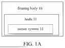


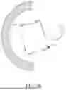
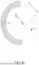
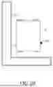


Sources:
- United States Patent and Trademark Office - verify current appl. status at the USPTO↗
Recent applications in this class:
- » 20260159204 2026-06-11
SYSTEM FOR AND METHOD OF REMOTELY OPERATING WATERCRAFT - » 20260116516 2026-04-30
INFORMATION PROCESSING APPARATUS, INFORMATION PROCESSING METHOD, AND STORAGE MEDIUM - » 20260097833 2026-04-09
MANAGING PASSENGER TRANSPORT BETWEEN MARINE VESSELS - » 20260062104 2026-03-05
MAINTENANCE MANAGEMENT METHOD FOR A SHIP - » 20260042520 2026-02-12
WATERCRAFT - » 20260028098 2026-01-29
MOBILE ENERGY HARVESTING DEVICE FOR ENERGY GENERATION, CONVERSION, AND DELIVERY - » 20260021877 2026-01-22
Feasible Forces and Torque of a Vessel - » 20260008526 2026-01-08
DEVICE AND METHOD FOR SENSING AND CORRECTING MARINE TRANSPORTATION ENVIRONMENT OF SHIP - » 20250376250 2025-12-11
MARINE INPUT DEVICE SATURATION - » 20250353582 2025-11-20
METHOD AND DEVICE FOR RELAYING ENGINE CONTROL MESSAGE
Recent applications for this Assignee:
- » 19037909 2026-05-26
Floating body apparatus and system