STORAGE BOX HAVING PLATE-SHAPED WALL STRUCTURE AND CAPABLE OF BEING REPEATEDLY DISASSEMBLED AND ASSEMBLED
US20260176019A1
2026-06-25
19/028,212
2025-01-17
Smart Summary: A storage box is designed with flat walls that can be easily taken apart and put back together. It consists of two types of walls: first, second, and third plate-shaped walls. When assembled, the first and second walls fit between the third walls, creating a sturdy structure. Special heads on the walls fit into grooves on other walls to hold everything together securely. The box can be disassembled and reassembled multiple times without losing its strength. 🚀 TL;DR
Abstract:
A storage box having a plate-shaped wall structure and capable of being repeatedly disassembled and assembled includes two first plate-shaped walls, two second plate-shaped walls, and two third plate-shaped walls. When the storage box is in an assembled state, the two first plate-shaped walls and the two second plate-shaped walls are located between the two third plate-shaped walls, the two first plate-shaped walls are located between the two second plate-shaped walls, first insertion heads of the first plate-shaped walls are inserted into first insertion grooves of the second plate-shaped walls, second insertion heads of the first plate-shaped walls are inserted into second insertion grooves of the third plate-shaped walls, third insertion heads of the second plate-shaped walls are inserted into third insertion grooves of the third plate-shaped walls, and the third plate-shaped walls are connected to the first plate-shaped walls or the second plate-shaped walls via unlockable first locking structures.
Assignee:
- Taizhou Niu Shang Niu Trading Co., Ltd. 1 🇨🇳 Taizhou, China
Applicant:
Interested in similar patents?
Get notified when new applications in this technology area are published.
Classification:
B65D11/1873 » CPC main
Containers having bodies formed by interconnecting or uniting two or more rigid, or substantially rigid, components made wholly or mainly of plastics material collapsible, i.e. with walls hinged together or detachably connected with detachable components all walls are detached from each other to collapse the container
Description
CROSS REFERENCE TO RELATED APPLICATIONS
This application claims priority benefits to Chinese Patent Application No. 2024232167549, filed on Dec. 25, 2024; the contents of which are incorporated herein by reference.
TECHNICAL FIELD
The present disclosure belongs to the technical field of household items, relates to a storage box, and in particular, to a storage box having a plate-shaped wall structure and capable of being repeatedly disassembled and assembled.
BACKGROUND
With the continuous change in living space of people and increasingly refined demands for storage and organization, storage boxes have become indispensable items in many scenes such as home, office, and travel. Traditional storage boxes are usually designed in a fixed structure, which occupies a large storage space when not in use and is inconvenient to carry and store. This problem has become increasingly prominent in modern life where space resources are insufficient, prompting people to seek a more flexible storage solution with high space utilization.
SUMMARY
The present disclosure provides a storage box having a plate-shaped wall structure and capable of being repeatedly disassembled and assembled. The technical problem to be solved by the present disclosure is how to provide a storage box which is assembled from plate-shaped walls and can be repeatedly disassembled and assembled, to improve the convenience of disassembling and assembling the storage box.
The technical problem to be solved by the present disclosure can be realized by the following technical solutions. A storage box having a plate-shaped wall structure and capable of being repeatedly disassembled and assembled includes two first plate-shaped walls, two second plate-shaped walls, and two third plate-shaped walls; the first plate-shaped wall includes a rectangular first wall body, two opposite side surfaces of the first wall body are provided with one group of first insertion heads, and the other two opposite side surfaces are provided with one group of second insertion heads; the second plate-shaped wall includes a rectangular second wall body, the second wall body is provided with two groups of first insertion grooves in one-to-one correspondence to the two groups of first insertion heads of the first plate-shaped wall, and two opposite side surfaces of the second wall body are provided with one group of third insertion heads; the third plate-shaped wall includes a rectangular third wall body, the third wall body is provided with two groups of second insertion grooves in one-to-one correspondence to the two groups of second insertion heads of the first plate-shaped wall, and the third wall body is further provided with two groups of third insertion grooves in one-to-one correspondence to the two groups of third insertion heads of the second plate-shaped wall; a put-in/take-out opening is formed in the first wall body of either of the first plate-shaped walls, or in the second wall body of either of the second plate-shaped walls, or in the third wall body of either of the third plate-shaped walls; when the storage box is in an assembled state, the six plate-shaped walls define a storage space, the two first plate-shaped walls and the two second plate-shaped walls are located between the two third plate-shaped walls disposed in parallel, the two first plate-shaped walls are located between the two second plate-shaped walls disposed in parallel, the two first plate-shaped walls are disposed in parallel, the first insertion head of the first plate-shaped wall is inserted into the first insertion groove of the second plate-shaped wall, the second insertion head of the first plate-shaped wall is inserted into the second insertion groove of the third plate-shaped wall, and the third insertion head of the second plate-shaped wall is inserted into the third insertion groove of the third plate-shaped wall; and when the storage box is in the assembled state, the two third plate-shaped walls and the two first plate-shaped walls or the two third plate-shaped walls and the two second plate-shaped walls are both connected via unlockable first locking structures.
When the storage box is in a disassembled state, the six plate-shaped walls can be stacked to reduce the space occupied by the storage box when the storage box is not in use. The process of switching the storage box from the disassembled state to the assembled state is roughly as follows: first, the two parallel first plate-shaped walls are disposed between the two parallel second plate-shaped walls, and the first insertion head is inserted into the first insertion groove; then, the two first plate-shaped walls and two second plate-shaped walls are disposed between the two third plate-shaped walls disposed in parallel, the second insertion head is inserted into the second insertion groove, and the third insertion head is inserted into the third insertion groove; and finally, the first locking structure is operated to be in a locked state, so that the second plate-shaped wall and the third plate-shaped wall are in the locked state, that is, the second plate-shaped wall and the third plate-shaped wall will not be naturally separated when the storage box is arbitrarily flipped over and shaken. When the storage box is in the assembled state, the put-in/take-out opening may be provided upward or horizontally. Based on actual usage, any plate-shaped wall can be used as the bottom wall of the storage box.
Assuming that the put-in/take-out opening is formed in the first wall body of one first plate-shaped wall, the same structure can be used for the two second plate-shaped walls or the two third plate-shaped walls, thereby reducing the manufacturing cost of the storage box and improving the convenience of disassembling and assembling the storage box.
The process of switching the storage box from the assembled state to the disassembled state is roughly as follows: first, the first locking structure is operated to be in the unlocked state; then, the third plate-shaped wall is moved along a thickness direction of the third plate-shaped wall to separate the third plate-shaped walls from the two first plate-shaped walls and the two second plate-shaped walls; and finally, the second plate-shaped wall is moved along a thickness direction of the second plate-shaped wall to separate the second plate-shaped walls from the two first plate-shaped walls. Preferably, the six plate-shaped walls can be stacked, which is conducive to the storage of the storage box.
Compared with the related art, the storage box is convenient to be disassembled and assembled. The first locking structure can be repeatedly locked and unlocked, and the insertion head can be repeatedly inserted into and removed from the insertion groove, so that the storage box can be repeatedly disassembled and assembled. The six side walls of the storage box all use a plate-shaped structure, and some side walls may use the same components based on the situation, to reduce the manufacturing cost and improve the convenience of disassembly and assembly.
When the storage box having a plate-shaped wall structure and capable of being repeatedly disassembled and assembled is in the assembled state, a side surface of the first wall body of the first plate-shaped wall abuts against an inner plate surface of the second plate-shaped wall, a side surface of the first wall body of the first plate-shaped wall abuts against an inner plate surface of the third plate-shaped wall, a side surface of the second wall body of the second plate-shaped wall abuts against the inner plate surface of the third plate-shaped wall, and the first locking structure is configured to limit the movement of the first plate-shaped wall relative to the third plate-shaped wall in a direction in which the second insertion head is inserted into the second insertion groove, or the first locking structure is configured to limit the movement of the second plate-shaped wall relative to the third plate-shaped wall in a direction in which the third insertion head is inserted into the third insertion groove.
When the storage box having a plate-shaped wall structure and capable of being repeatedly disassembled and assembled is in the assembled state, the two first plate-shaped walls and the two second plate-shaped walls are also connected via second locking structures, and the second locking structure is configured to limit the movement of the first plate-shaped wall relative to the second plate-shaped wall in a direction in which the first insertion head is inserted into the first insertion groove.
Preferably, the first locking structure has the same structure as the second locking structure.
In the storage box having a plate-shaped wall structure and capable of being repeatedly disassembled and assembled, the first locking structure includes a T-shaped lock and an insertion sheet provided with a locking slot, the T-shaped lock includes a cap portion and a rod portion, the rod portion is fixedly connected to the side surface of the first wall body of the first plate-shaped wall or the side surface of the second wall body of the second plate-shaped wall, the insertion sheet is slidably connected to the third plate-shaped wall, an avoidance hole is formed in the third plate-shaped wall for the T-shaped lock to pass through, and when the rod portion is located in the locking slot, and the cap portion is in contact with the insertion sheet, the first locking structure is in a locked state.
In the storage box having a plate-shaped wall structure and capable of being repeatedly disassembled and assembled, a strip-shaped mounting groove is formed in an outer side surface of the third plate-shaped wall, the insertion sheet is located in the mounting groove, and the insertion sheet can move in a longitudinal line direction of the mounting groove. A limit stop strip is fixed in the mounting groove, the insertion sheet is located between the limit stop strip and a bottom wall of the mounting groove, a positioning groove is formed in the bottom wall of the mounting groove, a forming groove is formed in the insertion sheet for enclosing to form an elastic portion, and when the first locking structure is in the locked state, the elastic portion is embedded in the positioning groove to limit the movement of the insertion sheet.
In the storage box having a plate-shaped wall structure and capable of being repeatedly disassembled and assembled, the first locking structure includes a latch and a locking rod, one end of the latch is provided with a locking groove, the other end of the latch is rotatably connected to the first plate-shaped wall or the second plate-shaped wall via a shaft, the locking rod is fixedly connected to the third plate-shaped wall, and when the locking rod is embedded in the locking groove, the first locking structure is in a locked state.
BRIEF DESCRIPTION OF DRAWINGS
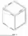
FIG. 1 is a schematic perspective structural diagram of a storage box with a door in a closed state according to Embodiment 1.
FIG. 2 is a schematic perspective structural diagram of the storage box with the door in an opened state according to Embodiment 1.
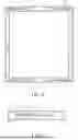
FIG. 3 is a schematic perspective structural diagram of the storage box in a disassembled state according to Embodiment 1.
FIG. 4 is a schematic top view of the storage box in an assembled state according to Embodiment 1.
FIG. 5 is a sectional view along A-A in FIG. 4.
FIG. 6 is a sectional view along B-B in FIG. 5.
FIG. 7 is a schematic right view of the storage box in the assembled state according to Embodiment 1.
FIG. 8 is a sectional view along C-C in FIG. 7.
FIG. 9 is an enlarged view of a partial structure in FIG. 8.
FIG. 10 is a schematic perspective structural diagram of a storage box in an assembled state according to Embodiment 2.
FIG. 11 is a schematic perspective structural diagram of the storage box in a disassembled state according to Embodiment 2.
FIG. 12 is a schematic right view of the storage box in the assembled state according to Embodiment 2.
FIG. 13 is a sectional view along D-D in FIG. 12.
FIG. 14 is an enlarged view of a partial structure in FIG. 13.
FIG. 15 is a sectional view along E-E in FIG. 12.
Description of reference numerals: 1: first plate-shaped wall; 1a: first wall body; 1b: first insertion head; 1c: second insertion head; 2: second plate-shaped wall; 2a: second wall body; 2b: first insertion groove; 2c: third insertion head; 3: third plate-shaped wall; 3a: third wall body; 3b: second insertion groove; 3c: third insertion groove; 4: put-in/take-out opening; 5: door; 6-1: first locking structure; 6-2: second locking structure; 6a: T-shaped lock; 6a1: cap portion; 6a2: rod portion; 6b: insertion sheet; 6b1: locking slot; 6b2: forming groove; 6b3: elastic portion; 6b4: sliding force portion; 6c: avoidance hole; 6d: mounting groove; 6e: limit stop strip; 6f: positioning groove; 6g: latch; 6g1: locking groove; 6h: locking rod.
DETAILED DESCRIPTION
The following describes in detail the technical solutions in the present disclosure by using specific embodiments of the present disclosure and with reference to the accompanying drawings, but the present disclosure is not limited to these embodiments.
Embodiment 1: As shown in FIG. 3, a storage box having a plate-shaped wall structure and capable of being repeatedly disassembled and assembled includes two first plate-shaped walls 1, two second plate-shaped walls 2, and two third plate-shaped walls 3.
The first plate-shaped wall 1 includes a rectangular first wall body 1a, two opposite side surfaces of the first wall body 1a are provided with one group of first insertion heads 1b, and the other two opposite side surfaces are provided with one group of second insertion heads 1c. In the accompanying drawings of this specification, one group of first insertion heads 1b includes two first insertion heads 1b, and one group of second insertion heads 1c includes two second insertion heads 1c.
The second plate-shaped wall 2 includes a rectangular second wall body 2a, the second wall body 2a is provided with two groups of first insertion grooves 2b in one-to-one correspondence to the two groups of first insertion heads 1b of the first plate-shaped wall 1, and two opposite side surfaces of the second wall body 2a are provided with one group of third insertion heads 2c. In the accompanying drawings of this specification, one group of third insertion heads 2c includes four third insertion heads 2c.
The third plate-shaped wall 3 includes a rectangular third wall body 3a, the third wall body 3a is provided with two groups of second insertion grooves 3b in one-to-one correspondence to the two groups of second insertion heads 1c of the first plate-shaped wall 1, and the third wall body 3a is further provided with two groups of third insertion grooves 3c in one-to-one correspondence to the two groups of third insertion heads 2c of the second plate-shaped wall 2.
In the accompanying drawings of this specification, a put-in/take-out opening 4 is formed in the first wall body 1a of one first plate-shaped wall 1, and the first plate-shaped wall 1 is rotatably connected to a door 5 for covering the put-in/take-out opening 4.
As shown in FIG. 1, FIG. 2, and FIG. 4 to FIG. 8, when the storage box is in an assembled state, the six plate-shaped walls define a storage space. The two first plate-shaped walls 1 and the two second plate-shaped walls 2 are located between the two third plate-shaped walls 3 disposed in parallel. The two first plate-shaped walls 1 are located between the two second plate-shaped walls 2 disposed in parallel. The two first plate-shaped walls 1 are disposed in parallel. The first insertion head 1b of the first plate-shaped wall 1 is inserted into the first insertion groove 2b of the second plate-shaped wall 2. A side surface of the first wall body 1a of the first plate-shaped wall 1 abuts against an inner plate surface of the second plate-shaped wall 2. The second insertion head 1c of the first plate-shaped wall 1 is inserted into the second insertion groove 3b of the third plate-shaped wall 3. A side surface of the first wall body 1a of the first plate-shaped wall 1 abuts against an inner plate surface of the third plate-shaped wall 3. The third insertion head 2c of the second plate-shaped wall 2 is inserted into the third insertion groove 3c of the third plate-shaped wall 3. A side surface of the second wall body 2a of the second plate-shaped wall 2 abuts against the inner plate surface of the third plate-shaped wall 3.
As shown in FIG. 1 to FIG. 9, the storage box further includes a plurality of groups of unlockable first locking structures 6-1 and a plurality of groups of unlockable second locking structures 6-2. When the storage box is in the assembled state, the two third plate-shaped walls 3 and the two second plate-shaped walls 2 are connected via the first locking structures 6-1. When in a locked state, the first locking structure 6-1 is configured to limit the movement of the second plate-shaped wall 2 relative to the third plate-shaped wall 3 in a direction in which the third insertion head 2c is inserted into the third insertion groove 3c, that is, limit the movement of the second plate-shaped wall 2 relative to the third plate-shaped wall 3 in a direction of an arrow X. The two first plate-shaped walls 1 and the two second plate-shaped walls 2 are connected via the second locking structures 6-2. When in a locked state, the second locking structure 6-2 is configured to limit the movement of the first plate-shaped wall 1 relative to the second plate-shaped wall 2 in a direction in which the first insertion head 1b is inserted into the first insertion groove 2b, that is, limit the movement of the second plate-shaped wall 2 relative to the first plate-shaped wall 1 in a direction of an arrow Y. In the accompanying drawings of this specification, each third plate-shaped wall 3 and each second plate-shaped wall 2 are connected via two groups of first locking structures 6-1, and each first plate-shaped wall 1 and each second plate-shaped wall 2 are connected via one group of second locking structures 6-2.
The structure and the principle of the first locking structure 6-1 are the same as those of the second locking structure 6-2. The locking structure includes a T-shaped lock 6a and an insertion sheet 6b provided with a locking slot 6b1. The T-shaped lock 6a includes a cap portion 6a1 and a rod portion 6a2. The rod portion 6a2 can be located in the lock slot 6b1 by moving the insertion sheet 6b, and the cap portion 6a1 is in contact with the insertion sheet 6b to achieve the locking function.
As shown in FIG. 8 and FIG. 9, the rod portion 6a2 of the first locking structure 6-1 is fixedly connected to the side surface of the second wall body 2a of the second plate-shaped wall 2, the insertion sheet 6b is slidably connected to the third plate-shaped wall 3, and an avoidance hole 6c is formed in the third plate-shaped wall 3 for the T-shaped lock 6a to pass through. Specifically, a strip-shaped mounting groove 6d is formed in an outer side surface of the third plate-shaped wall 3, the insertion sheet 6b is located in the mounting groove 6d, and the insertion sheet 6b can move in a longitudinal line direction of the mounting groove 6d. A limit stop strip 6e is fixed in the mounting groove 6d, and the insertion sheet 6b is located between the limit stop strip 6e and a bottom wall of the mounting groove 6d. A positioning groove 6f is formed in the bottom wall of the mounting groove 6d, and a forming groove 6b2 is formed in the insertion sheet 6b for enclosing to form an elastic portion 6b3 and is in a circuitous shape. When the rod portion 6a2 is located in the locking slot 6b1, the elastic portion 6b3 is embedded in the positioning groove 6f to limit the movement of the insertion sheet 6b, thereby reducing the possibility of accidental unlocking.
The first plate-shaped wall 1, the second plate-shaped wall 2, and the third plate-shaped wall 3 are all made of plastic. The positioning groove 6f is directly opposite to the limit stop strip 6e, which not only realizes that the limit stop strip 6e and the third plate-shaped wall 3 are integrally connected, improves the structural strength, but also simplifies the injection molding mold.
Differences between the second locking structure 6-2 and the first locking structure 6-1 lie in that the rod portion 6a2 of the second locking structure 6-2 is fixedly connected to the side surface of the first wall body 1a of the first plate-shaped wall 1, the mounting groove 6d configured to mount the insertion sheet 6b is located on an outer side surface of the second plate-shaped wall 2, and the avoidance hole 6c is also formed in the second plate-shaped wall 2.
The insertion sheet 6b is provided with a sliding force portion 6b4. When unlocking is required, a force is applied to the sliding force portion 6b4 to force the insertion sheet 6b to move in the longitudinal line direction of the mounting groove 6d until the T-shaped lock 6a is completely separated from the insertion sheet 6b.
Embodiment 2: As shown in FIG. 10 to FIG. 15, the structure and the principle of this embodiment are basically the same as those of Embodiment 1. Basic similarities are not described in detail, and only differences are described. Differences lie in that one group of first insertion heads 1b of the first plate-shaped wall 1 includes one first insertion head 1b, one group of second insertion heads 1c includes one second insertion head 1c, one group of third insertion heads 2c of the second plate-shaped wall 2 includes one third insertion head 2c, the put-in/take-out opening 4 is formed in a third wall body 3a of one third plate-shaped wall 3, and the third plate-shaped wall 3 is rotatably connected to the door 5 for covering the put-in/take-out opening 4.
As shown in FIG. 10 to FIG. 15, when the storage box is in the assembled state, the two third plate-shaped walls 3 and the two first plate-shaped walls 1 are both connected via the first locking structures 6-1. When in the locked state, the first locking structure 6-1 is configured to limit the movement of the first plate-shaped wall 1 relative to the third plate-shaped wall 3 in a direction in which the second insertion head 1c is inserted into the second insertion groove 3b. When the storage box is in the assembled state, the two first plate-shaped walls 1 and the two second plate-shaped walls 2 are also connected via the second locking structures 6-2. When in the locked state, the second locking structure 6-2 is configured to limit the movement of the first plate-shaped wall 1 relative to the second plate-shaped wall 2 in a direction in which the first insertion head 1b is inserted into the first insertion groove 2b.
The structure and the principle of the first locking structure 6-1 are the same as those of the second locking structure 6-2. The locking structure includes a latch 6g and a locking rod 6h, one end of the latch 6g is provided with a locking groove 6g1, and when the locking rod 6h is embedded in the locking groove 6g1, the locking structure is in the locked state. The other end of the latch 6g of the first locking structure 6-1 is rotatably connected to the first plate-shaped wall 1 via a shaft, and the locking rod 6h is fixedly connected to the third plate-shaped wall 3. The other end of the latch 6g of the second locking structure 6-2 is rotatably connected to the first plate-shaped wall 1 via a shaft, and the locking rod 6h is fixedly connected to the second plate-shaped wall 2. One end of the locking rod 6h is provided with a pulling force portion, and when unlocking is required, a force is applied to the pulling force portion to force the locking rod 6h to swing until the locking rod 6h is completely separated from the locking groove 6g1.
Claims
1. A storage box having a plate-shaped wall structure and capable of being repeatedly disassembled and assembled, comprising two first plate-shaped walls (1), two second plate-shaped walls (2), and two third plate-shaped walls (3), wherein each first plate-shaped wall (1) of the two first plate-shaped walls (1) comprises a rectangular first wall body (1a), two opposite side surfaces of the first wall body (1a) are provided with one group of first insertion heads (1b), and another two opposite side surfaces are provided with one group of second insertion heads (1c);
each second plate-shaped wall (2) of the two second plate-shaped walls (2) comprises a rectangular second wall body (2a), the second wall body (2a) is provided with two groups of first insertion grooves (2b) in one-to-one correspondence to the two groups of first insertion heads (1b) of a corresponding first plate-shaped wall (1), and two opposite side surfaces of the second wall body (2a) are provided with one group of third insertion heads (2c);
each third plate-shaped wall (3) of the two third plate-shaped walls (3) comprises a rectangular third wall body (3a), the third wall body (3a) is provided with two groups of second insertion grooves (3b) in one-to-one correspondence to the two groups of second insertion heads (1c) of a corresponding first plate-shaped wall (1), and the third wall body (3a) is further provided with two groups of third insertion grooves (3c) in one-to-one correspondence to the two groups of third insertion heads (2c) of a corresponding second plate-shaped wall (2);
a put-in/take-out opening (4) is formed in the first wall body (1a) of either of the two first plate-shaped walls (1), or in the second wall body (2a) of either of the two second plate-shaped walls (2), or in the third wall body (3a) of either of the two third plate-shaped walls (3);
when the storage box is in an assembled state, the six plate-shaped walls define a storage space, the two first plate-shaped walls (1) and the two second plate-shaped walls (2) are located between the two third plate-shaped walls (3) disposed in parallel, the two first plate-shaped walls (1) are located between the two second plate-shaped walls (2) disposed in parallel, the two first plate-shaped walls (1) are disposed in parallel, the first insertion heads (1b) of each first plate-shaped wall (1) are inserted into the first insertion grooves (2b) of a corresponding second plate-shaped wall (2), the second insertion heads (1c) of each first plate-shaped wall (1) are inserted into the second insertion grooves (3b) of a corresponding third plate-shaped wall (3), and the third insertion heads (2c) of the second plate-shaped wall (2) are inserted into the third insertion grooves (3c) of a corresponding third plate-shaped wall (3); and
when the storage box is in the assembled state, the two third plate-shaped walls (3) and the two first plate-shaped walls (1), or the two third plate-shaped walls (3) and the two second plate-shaped walls (2) are both connected via unlockable first locking structures (6-1).
2. The storage box having a plate-shaped wall structure and capable of being repeatedly disassembled and assembled according to claim 1, wherein when the storage box is in the assembled state, a side surface of each first wall body (1a) of the two first plate-shaped walls (1) abuts against an inner plate surface of a corresponding second plate-shaped wall (2), another side surface of the first wall body (1a) of each first plate-shaped wall (1) abuts against an inner plate surface of a corresponding third plate-shaped wall (3), a side surface of the second wall body (2a) of each second plate-shaped wall (2) abuts against the inner plate surface of a corresponding third plate-shaped wall (3), and the first locking structure (6-1) is configured to limit a movement of each first plate-shaped wall (1) relative to a corresponding third plate-shaped wall (3) in a direction in which the second insertion heads (1c) are inserted into the second insertion grooves (3b), or the first locking structure (6-1) is configured to limit a movement of each second plate-shaped wall (2) relative to a corresponding third plate-shaped wall (3) in a direction in which the third insertion heads (2c) are inserted into the third insertion groove (3c).
3. The storage box having a plate-shaped wall structure and capable of being repeatedly disassembled and assembled according to claim 2, wherein when the storage box is in the assembled state, the two first plate-shaped walls (1) and the two second plate-shaped walls (2) are also connected via second locking structures (6-2), and the second locking structures (6-2) are configured to limit movements of the two first plate-shaped walls (1) relative to the two second plate-shaped walls (2) in a direction in which the first insertion heads (1b) are inserted into the corresponding first insertion grooves (2b).
4. The storage box having a plate-shaped wall structure and capable of being repeatedly disassembled and assembled according to claim 3, wherein each first locking structure (6-1) has the same structure as each second locking structure (6-2).
5. The storage box having a plate-shaped wall structure and capable of being repeatedly disassembled and assembled according to claim 1, wherein each first locking structure (6-1) comprises a T-shaped lock (6a) and an insertion sheet (6b) provided with a locking slot (6b1), the T-shaped lock (6a) comprises a cap portion (6a1) and a rod portion (6a2), the rod portion (6a2) is fixedly connected to the side surface of the first wall body (1a) of a corresponding first plate-shaped wall (1) or the side surface of the second wall body (2a) of a corresponding second plate-shaped wall (2), the insertion sheet (6b) is slidably connected to a corresponding third plate-shaped wall (3), an avoidance hole (6c) is formed in each third plate-shaped wall (3) for a corresponding T-shaped lock (6a) to pass through; and when the rod portion (6a2) is located in the locking slot (6b1), and the cap portion (6a1) is in contact with the insertion sheet (6b), the first locking structure (6-1) is in a locked state.
6. The storage box having a plate-shaped wall structure and capable of being repeatedly disassembled and assembled according to claim 5, wherein a strip-shaped mounting groove (6d) is formed in an outer side surface of each third plate-shaped wall (3), the insertion sheet (6b) is located in the mounting groove (6d), the insertion sheet (6b) is configured to move along a longitudinal line direction of the mounting groove (6d), a limit stop strip (6e) is fixed in the mounting groove (6d), the insertion sheet (6b) is located between the limit stop strip (6e) and a bottom wall of the mounting groove (6d), a positioning groove (6f) is formed in the bottom wall of the mounting groove (6d), a forming groove (6b2) is formed in the insertion sheet (6b) for enclosing to form an elastic portion (6b3); and when the first locking structure (6-1) is in the locked state, the elastic portion (6b3) is embedded in the positioning groove (6f) to limit a movement of the insertion sheet (6b).
7. The storage box having a plate-shaped wall structure and capable of being repeatedly disassembled and assembled according to claim 1, wherein the first locking structure (6-1) comprises a latch (6g) and a locking rod (6h), one end of the latch (6g) is provided with a locking groove (6g1), another end of the latch (6g) is rotatably connected to a corresponding first plate-shaped wall (1) or a corresponding second plate-shaped wall (2) via a shaft, the locking rod (6h) is fixedly connected to a corresponding third plate-shaped wall (3); and when the locking rod (6h) is embedded in the locking groove (6g1), the first locking structure (6-1) is in a locked state.
Images & Drawings included:


Sources:
- United States Patent and Trademark Office - verify current appl. status at the USPTO↗
Recent applications in this class:
- » 20260152319 2026-06-04
MODULAR CLIMATE CONTROL CONTAINER - » 20250304317 2025-10-02
FOLDABLE STORAGE DEVICE - » 20240253855 2024-08-01
TRAY, STACK OF TRAYS AND METHOD FOR LOADING/UNLOADING TRAYS - » 20240228108 2024-07-11
STORAGE BOX AND PACKAGING STRUCTURE THEREOF - » 20240132247 2024-04-25
STORAGE BOX AND PACKAGING STRUCTURE THEREOF - » 20240083623 2024-03-14
DECK STORAGE BOX - » 20230365298 2023-11-16
ASSEMBLY FOR BOX - » 20230117878 2023-04-20
Storage box and packaging structure thereof - » 20230067173 2023-03-02
Compact wall panel deck box kit - » 20230039288 2023-02-09
Deck storage box