PLATE COMPACTOR TRANSPORT DEVICE
US20260176830A1
2026-06-25
19/343,710
2025-09-29
Smart Summary: A new device helps move a plate compactor easily between two modes: transport and working. It has arms that can swing up and down, which are attached to the back of the compactor. These arms can be locked in a raised position to keep them from moving when not in use. When it's time to transport, the lock can be released, allowing the arms to drop down and the wheels to touch the ground. This design is strong enough to handle the vibrations from the compactor while being safe and simple to use. 🚀 TL;DR
Abstract:
A transport device is provided to allow a plate compactor to be switched between transport and non-transport modes in a very simple and safe manner, while also providing sufficient durability against vibratory wear. Arms are pivotably attached to a base 2 on a rear side of the plate compactor 9 such as to be pivotable between a position higher than the plate 91 and a lower position. An arm lock means includes a stopper for limiting upward pivoting of the arms, and a lock lever 6 having a hook adapted to engage the stopper. The arms can be locked in the position higher than the plate 91 to stop the arms from pivoting by the hook of the lock lever 6 engaging the stopper. When the lock is released, the distal ends of the arms and the wheels 5 pivot downwards by their own weight until the wheels touch the ground behind the plate compactor.
Inventors:
- Kenichi NAGASAWA 2 🇯🇵 Saitama, Japan
- Masaya SEKIGUCHI 2 🇯🇵 Saitama, Japan
- Yuichi NAKAGOMI 2 🇯🇵 Saitama, Japan
Applicant:
Interested in similar patents?
Get notified when new applications in this technology area are published.
Classification:
E01C19/38 » CPC main
Machines, tools or auxiliary devices for preparing or distributing paving materials, for working the placed materials, or for forming, consolidating, or finishing the paving for consolidating or finishing laid-down unset materials; Tamping or vibrating apparatus other than rollers ; Devices for ramming individual paving elements; Power-driven rammers or tampers, e.g. air-hammer impacted shoes for ramming stone-sett paving; Hand-actuated ramming or tamping machines, e.g. tampers with manually hoisted dropping weight with means specifically for generating vibrations, e.g. vibrating plate compactors, immersion vibrators
E01C19/35 » CPC further
Machines, tools or auxiliary devices for preparing or distributing paving materials, for working the placed materials, or for forming, consolidating, or finishing the paving for consolidating or finishing laid-down unset materials; Tamping or vibrating apparatus other than rollers ; Devices for ramming individual paving elements; Power-driven rammers or tampers, e.g. air-hammer impacted shoes for ramming stone-sett paving; Hand-actuated ramming or tamping machines, e.g. tampers with manually hoisted dropping weight Hand-held or hand-guided tools
E02D3/046 » CPC further
Improving or preserving soil or rock, e.g. preserving permafrost soil; Improving by compacting by tamping or vibrating, e.g. with auxiliary watering of the soil
Description
CROSS-REFERENCE TO RELATED APPLICATION
This application claims the benefit of Japanese Patent Application No. 2024-228653 filed Dec. 25, 2024, the content of which is incorporated herein by reference in its entirety.
FIELD OF THE INVENTION
The present invention relates to a transport device for plate compactors used for the compaction of a paved or ground surface.
BACKGROUND OF THE INVENTION
A plate compactor, which is used for the compaction (compacting) of a paved or ground surface, has a large weight (e.g. approximately 40 to 100 kg). For transporting a plate compactor when not in use for compaction, the compactor has traditionally been carried on a customized transport cart, or moved using a wheeled transport device that can be attached to the machine body of the compactor.
When a customized transport cart is used, the compactor need to be loaded and unloaded each time, and the transport cart itself need to be brought to the site. A transport device that can be attached to the machine body of the compactor likewise requires attachment and detachment for each use. In both cases, moving a plate compactor was cumbersome.
Recently, plate compactors that come with integrated transport wheels, or with a folding wheeled transport device mounted in the rear part of the machine body, have also been developed and are commercially available.
PRIOR ART LITERATURE
Patent Literature
Patent Document 1: Japanese Laid-Open Patent Publication No. 2018-076737.
Patent Document 2: Japanese Laid-Open Patent Publication No. 2000-257017.
Patent Document 3: Japanese Laid-Open Patent Publication No. 2000-257019.
SUMMARY OF THE INVENTION
Technical Problem to be Solved by the Invention
However, conventional plate compactors that come with transport wheels had limited operability in compaction and maneuverability due to the location of the wheels that could be mounted only in a limited area. Conventional plate compactors with a folding frame transport device at the rear of the machine body have problems with ease of handling when deploying the frame and folding it up for storage. In addition, the moving parts (such as pivoting parts) that realize the folding structure are susceptible to vibration during compaction and are not sufficiently resistant to vibratory wear.
The present invention addresses these issues in the prior art. An object of the invention is to provide a plate compactor transport device that enables very simple and safe switching between transport and non-transport modes, while also providing sufficient durability against vibratory wear.
Means for Solving the Problem
A plate compactor transport device according to the present invention is adapted to be mounted on a plate compactor, and includes a base, an arm, a wheel, an arm lock means, and an arm biasing means. The base is fixedly attached to a plate via an anti-vibration means in a position above the plate. The wheel is rotatably supported at a distal end of the arm. The arm has a proximal end pivotably attached to the base on a rear side of the plate compactor so as to allow the distal end of the arm to pivot between a position higher than the plate and a lower position. The arm lock means includes: a stopper configured to limit upward pivoting of the arm; and a lock lever having a hook configured to engage the stopper. The arm lock means is configured: to lock the arm in the position higher than the plate to stop the arm from pivoting by the hook of the lock lever engaging the stopper; and to release the arm to allow the distal end of the arm and the wheel to pivot downwards by their own weight until the wheel touches a ground surface behind the plate compactor. The arm biasing means is configured to bias the distal end of the arm and the wheel toward a position below the plate when the plate compactor is leaned forward from an orientation in which the wheel is in contact with the ground surface behind the plate compactor.
In the plate compactor transport device, preferably, the base includes a support, and the proximal end of the arm is pivotably attached to the support. The lock lever is pivotably attached to the arm, while the stopper is fixedly attached to the support. A lock lever biasing means is disposed between the support and the lock lever to bias the lock lever in a direction for the hook to engage the stopper when the arm is in close proximity to the stopper.
Preferably, the transport device includes a spring with one end anchored to the support and the other end anchored to the lock lever, this spring serving as the lock lever biasing means as well as the arm biasing means. Preferably, the stopper is fixedly attached to the support via an anti-vibration means. Preferably, the transport device includes a handle lock device adapted to lock the operation handle in a backward inclined position.
Effects of the Invention
The plate compactor transport device according to the present invention is used by being mounted on a plate compactor, and allows the plate compactor on which it is mounted to be switched from a non-transport mode (in which compaction can be performed) to a transport mode (in which the plate compactor can be readily moved about with the wheels touching the ground), and vice versa, in a very simple and yet safe manner.
The plate compactor transport device according to the present invention adopts anti-vibration measures in necessary parts and is expected to provide sufficient durability against vibratory wear even though it includes an integral structure that allows switching between non-transport and transport modes (a structure including moving parts).
BRIEF DESCRIPTION OF THE DRAWINGS
FIG. 1 is a side view of a plate compactor transport device 1 according to the present invention;
FIG. 2 is a perspective view of the supports 3, frame 4, and wheels 5 shown in FIG. 1;
FIG. 3 is a diagram showing a state of a lock lever 6 mounted on the arm 41 shown in FIG. 2;
FIG. 4 is a side view of the proximal end of the operation handle 93 and the handle lock device 7 shown in FIG. 1;
FIG. 5 is an illustrative diagram depicting an operating state of the transport device 1 shown in FIG. 1;
FIG. 6 is an illustrative diagram depicting an operating state of the transport device 1 shown in FIG. 1;
FIG. 7 is an illustrative diagram depicting an operating state of the transport device 1 shown in FIG. 1;
FIG. 8 is an illustrative diagram depicting an operating state of the transport device 1 shown in FIG. 1; and
FIG. 9 is an illustrative diagram depicting an operating state of the transport device 1 shown in FIG. 1.
DETAILED DESCRIPTION OF THE INVENTION
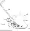
Hereinafter, an embodiment of the PLATE COMPACTOR TRANSPORT DEVICE according to the present invention is described with reference to the accompanying drawings. FIG. 1 is a side view of the plate compactor transport device 1 (hereinafter simply referred to as “transport device 1”) according to the present invention. As shown, this transport device 1 is mounted on a plate compactor 9 for use. The plate compactor 9 shown in FIG. 1 has a general design and includes: a plate 91 (compaction plate) for the compaction of a paved or ground surface; a main unit 92 placed on the plate (including a vibrator for oscillating the plate 91, an engine and a fuel tank or an electric motor and a battery for driving the vibrator); and an operation handle 93.
The transport device 1 according to the present invention comprises a base 2, a frame 4 (arms 41), wheels 5, an arm lock means (e.g., a lock lever 6), an arm biasing means, and a handle lock device 7. Of these, the base 2 is a part for fixedly attaching the transport device 1 to the plate compactor 9, and is mounted above the plate 91 via an anti-vibration means (e.g., anti-vibration rubber) to dampen the vibration transmitted from the vibrator and the plate 91. More specifically, the base 2 is fixed to the plate 91 via the anti-vibration means, or fixed to a machine frame or the like that is mounted on the plate 91 via the anti-vibration means.
As shown in FIG. 1, the base 2 includes supports 3 at the rear (of the machine body of the plate compactor 9 on which the transport device is mounted). The supports 3 are provided for supporting the frame 4 such as to be pivotable about a horizontal axis.
FIG. 2 is a perspective view of the supports 3, frame 4, and wheels 5 shown in FIG. 1. In this embodiment, as shown in this drawing, two plate-like supports 3 spaced apart in the width direction (of the machine body of the plate compactor 9 on which the transport device is mounted) are each fixedly attached to (or integrally formed on) a rear part of the main body of the base 2 (see FIG. 1) and coupled together by a horizontally extending rod-like reinforcing member 31.
The frame 4, which rotatably supports the wheels 5, is mounted on the supports 3. The frame 4 is composed of two arms 41 of the same shape and one shaft 44. The two arms 41 have a bent or curved shape as shown, and coupled together by the shaft 44 disposed between the distal ends 42 of the arms 41. The proximal end 43 of each arm 41 is pivotably attached to each of the two supports 3 (portions of the base 2). Namely, the arms 41 are supported such as to allow their distal ends 42 to pivot about a horizontal axis C1 shown in FIG. 2 (the line passing the centers of bolts 32 inserted into the through holes formed in the supports 3) between a position higher than the plate 91 (see FIG. 1) and a position lower than the plate 91 at the rear of the machine body of the plate compactor 9 (see FIG. 1). The wheels 5 are each attached to the distal ends 42 of the arms 41 (on both ends of the shaft 44).
As shown in FIG. 2, a stopper 33 (arm lock means) is fixedly provided to one support 3 to stop the upward pivoting of the arms 41 at a predetermined position. The stopper 33 is protruded sideways from a side face of the support 3 and located on the front side (of the machine body of the plate compactor 9 on which the transport device is mounted), and on the upper side, of the pivot point (i.e., the center of the bolts 32) of the arms 41, so that when the arms 41 and the wheels 5 are turned upwards, the stopper 33 will contact the arms 41 before the arms 41 and the wheels 5 contact the operation handle 93 (at a position where the arms 41 and the wheels 5 do not contact the operation handle 93). The stopper 33 is attached to the support 3 via an anti-vibration means (e.g., anti-vibration rubber).
The support 3 also includes a fixed pin (first anchor pin 34) for anchoring one end of a spring that is provided for biasing the lock lever 6 (arm lock means) shown in FIG. 1. The first anchor pin 34 protrudes from the side face of the support 3 in the same direction as the stopper 33. One of the two arms 41 is provided with a hole 45 for pivotably supporting the lock lever 6 shown in FIG. 1, and a slot 46 to limit the pivoting range (angle range) of the lock lever 6.
FIG. 3 is a diagram showing a state of the lock lever 6 mounted on the arm 41 shown in FIG. 2. As shown, the lock lever 6 is pivotably attached to the arm 41 by a bolt 61, and supported such as to be pivotable about a horizontal axis C2 (the line passing the center of the bolt 61 inserted into the hole 45 (see FIG. 2) formed in the arm 41).
The lock lever 6 is formed with a hook 62 on one side and a grip 63 on the other side of the pivot point (bolt 61). The hook 62 is sized to engage the stopper 33 and is positioned to engage the stopper 33 when the arm 41 contacts (or comes close to) the stopper 33. A second anchor pin 64 is formed between the pivot point (bolt 61) and the hook 62 of the lock lever 6. The second anchor pin 64 protrudes from the side face of the lock lever 6 in the same direction as the first anchor pin 34.
A projection 65 is formed on the side opposite to the second anchor pin 64 (on a side face of the lock lever 6 opposite to the side face where the second anchor pin 64 protrudes). The projection 65 protrudes into the slot 46 formed in the arm 41 to limit the pivoting range (angle range) of the lock lever 6 together with the slot 46. Namely, the lock lever 6 is allowed to pivot within the range of movement of the projection 65 protruding into the slot 46 and moving between the upper edge and the lower edge of the slot 46.
As shown in FIG. 3, a spring 8 (tension coil spring) is stretched between the support 3 and the lock lever 6. More specifically, one end of the spring 8 is anchored to the first anchor pin 34 of the support 3, and the other end of the spring 8 is anchored to the second anchor pin 64 of the lock lever 6. The lock lever 6 is biased by this spring 8 (lock lever biasing means) in the direction for the hook 62 to engage the stopper 33 when the arm 41 is in close proximity to the stopper 33.
FIG. 4 is a side view of the proximal end of the operation handle 93 and the handle lock device 7 shown in FIG. 1. The operation handle 93 is mounted on a machine body frame of the plate compactor 9 (see FIG. 1) such as to be pivotable about a hinge 94. The orientation of the handle can be changed from a backward inclined position (shown with solid lines in FIG. 4) to a forward inclined position (shown with one-dot chain lines in FIG. 4), or a perpendicular upright position. The operation handle 93 can be maintained fixedly at the backward inclined position (shown with solid lines in FIG. 4) by operating the handle lock device 7.
More specifically, the handle lock device 7 comprises a cylinder 71, an axially slidable rod 72 held inside the cylinder 71, and a tab 73, and is attached close to the proximal end of the operation handle 93. By operating the tab 73, the rod 72 can be switched between a state in which the distal end of the rod 72 is retracted inside the cylinder 71 (positioned as shown with broken lines in FIG. 4) and a state in which the distal end of the rod is extended out from the end of the cylinder 71 (positioned as shown with solid lines in FIG. 4). As also shown in FIG. 4, the base 2 has a fan-shaped guard 21 fixedly attached thereto such as to cover the vicinity of the proximal end of the operation handle 93 from the outside.
With the operation handle 93 located at the backward inclined position as shown with the solid lines in FIG. 4, the tab 73 is operated to cause the distal end of the rod 72 to extend out from the end of the cylinder 71. The distal end of the rod 72 making contact with a rear end portion of the guard 21 stops the forward pivoting of the operation handle 93. That is to say, the operation handle 93 can be locked to its backward inclined position.
Operating the tab 73 to cause the distal end of the rod 72 to be retracted inside the cylinder 71 as shown with broken lines in FIG. 4 releases the lock of the operation handle 93, allowing the operation handle 93 to freely pivot to the position shown with the one-dot chain lines in FIG. 4.
The operation modes of the transport device 1 according to this embodiment are now described. In the transport device 1 shown in FIG. 1, the plate compactor 9 is in its non-transport mode (in which compaction can be performed). The arms 41 and the wheels 5 are maintained in a position where they do not obstruct the compacting operation using the plate compactor 9 (behind the machine body and higher than the plate 91). More specifically, the arm 41 is positioned in contact with the stopper 33 as shown in FIG. 3, and the hook 62 of the lock lever 6 is engaged with the stopper 33, preventing the arm 41 from pivoting. From this state, the plate compactor 9 can be switched to the transport mode (with the wheels 5 touching the ground for easy movement of the plate compactor 9) with a simple operation.
First, the handle lock device 7 is operated to lock the operation handle 93 in its backward inclined state as shown with solid lines in FIG. 4. Next, the lock lever 6 is operated to release the hook 62 from the stopper 33. Specifically, the grip 63 of the lock lever 6 is pushed down to pivot the lock lever 6 from the position shown with the solid lines in FIG. 3 to the position shown with the one-dot chain lines (where the hook 62 does not engage the stopper 33).
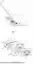
This releases the lock on the arms 41, allowing them to pivot. The arms 41 and the wheels 5 pivot mostly by their own weight until the wheels 5 make contact with the ground surface G (ground) on which the plate compactor 9 is placed, as shown in FIG. 5. In this state, an upper part of the operation handle 93 is gripped and pushed up to the front of the machine body of the plate compactor 9 (toward a point diagonally above and front of the machine body), to bring the plate compactor 9 to a forward leaning orientation (with the rear part of the plate 91 lifted up from the ground surface G) as shown in FIG. 6.
As the rear part of the plate 91 is lifted up from the ground surface G, the wheels 5 and the distal ends of the arms 41 pivot toward a position below a rear part of the plate 91 by their own weight and by the biasing force of the spring 8 (arm biasing means). The arms 41 are formed with stepped portions 47 (a part of each arm 41 protruding outwardly more than the radius of the wheel 5 to prevent the wheel 5 from contacting the plate 91). The arms 41 and wheels 5 stop when these stepped portions 47 come into contact with the plate 91 and stay stable.
This feature will be described in more detail. When the wheels 5 are in contact with the ground surface G before the plate compactor 9 is brought to its forward leaning orientation, the center line of the spring 8 (line connecting the first anchor pin 34 and the second anchor pin 64) is located above the pivot point of the arms 41 (center of the bolts 32) as shown in FIG. 5. From this state, as the rear part of the plate 91 is lifted up and when the angle of the plate 91 relative to the ground surface G exceeds a certain limit, the center line of the spring 8 (line connecting the first anchor pin 34 and the second anchor pin 64) moves down below the pivot point of the arms 41 (center of the bolts 32) as shown in FIG. 7.
As the rear part of the plate 91 is further lifted up, the wheels 5 and the distal ends of the arms 41 are pulled by the spring 8 towards the position below the rear part of the plate 91, until the stepped portions 47 of the arms 41 come into contact with the plate 91 as shown in FIG. 6. The biasing force (tension) of the spring 8 maintains the arms 41 and wheels 5 in this state in a stable manner.
Next, the operation handle 93 is returned to the rear of the machine body to bring the wheels 5 in contact with the ground surface G. From this state, pulling the operation handle 93 further backwards lifts up the front part of the plate 91 from the ground surface G as shown in FIG. 8. In this state, the entire weight of the plate compactor 9 is supported by the wheels 5, so that the plate compactor 9 can be freely moved back and forth or diagonally by gripping and maneuvering the operation handle 93.
Without the spring 8 that pulls the wheels 5 and the distal ends of the arms 41 towards the position below the rear part of the plate 91, the wheels 5 and the distal ends of the arms 41 will oscillate for a while below the pivot point of the arms 41 (center of the bolts 32) when the rear part of the plate 91 is lifted up from the state shown in FIG. 5. Bringing the wheels 5 down on the ground surface G before the oscillating movement stops is very dangerous because the wheels 5 may fail to come to the correct position below the plate 91 and slip back to the rear of the plate 91 (return to the state shown in FIG. 5).
In the transport device 1 according to this embodiment, when the rear part of the plate 91 is lifted up, the wheels 5 and the distal ends of the arms 41 are pulled by the spring 8 and come to the correct position below the plate 91, and maintained stably in this state. Therefore, the risk of the wheels 5 slipping back to the rear of the plate 91 can be avoided.
To switch from the transport mode shown in FIG. 8 (in which the plate compactor 9 can be readily moved about) to the non-transport mode shown in FIG. 1 (in which compaction can be performed), the plate compactor 9 is first leaned forward as shown in FIG. 6 to lift up the wheels 5 from the ground surface G. The arms 41 and the wheels 5 are then pivoted from the position below the plate 91 to the rear of the machine body and further upwards to the position shown in FIG. 1, more specifically, to the position where the arm 41 contacts the stopper 33 as shown in FIG. 3.
When the arms 41 and the wheels 5 are lifted up at the rear of the machine body, the center line of the spring 8 (line connecting the first anchor pin 34 and the second anchor pin 64) is located above the pivot point of the arms 41 (center of the bolts 32). Therefore, the tension of the spring 8 increases as the arms 41 pivot, assisting the pivoting of the arms 41 and allowing smooth switching to the non-transport mode.
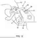
A latch device adopted in the lock lever 6 mounted on the arm 41, to work with the stopper 33 and the spring 8, causes the hook 62 of the lock lever 6 to automatically engage the stopper 33 as soon as the arm 41 contacts the stopper 33. More specifically, the distal end of the lock lever 6 has a tapered portion 66 as shown in FIG. 9. The tapered portion 66 is positioned to make contact with the stopper 33 first as the arm 41 pivots toward the stopper 33. After making contact with the stopper, the tapered portion slides on an outer circumferential surface of the stopper 33 as the arm 41 pivots further. The taper angle causes the distal end of the lock lever 6 to pivot upwards.
As described above, the hook 62 of the lock lever 6 is positioned to engage the stopper 33 when the arm 41 is in contact with the stopper 33. Moreover, the lock lever 6 is biased by the spring 8 in the direction for the hook 62 to engage the stopper 33. Therefore, the hook 62 automatically engages the stopper 33 when the arm 41 comes into contact with the stopper 33.
The switching operation from the transport mode shown in FIG. 8 to the non-transport mode shown in FIG. 1 can be carried out, for example, as follows: An operator grips the operation handle 93, and, while keeping the plate compactor 9 in the forward leaning orientation, hooks the tip of the foot on the shaft 44 shown in FIG. 2, pulls the shaft 44 to the back of the machine body, and lifts it up slowly as if kicking. Alternatively, the shaft 44 can be operated manually by another person while the operator grips the operation handle 93.
As described above, the transport device 1 according to this embodiment allows the plate compactor 9 on which it is mounted to be switched from the non-transport mode (in which compaction can be performed) to the transport mode (in which the plate compactor can be readily moved about with the wheels touching the ground), and vice versa, in a very simple and yet safe manner.
The transport device adopts anti-vibration measures in necessary parts and is expected to provide sufficient durability against vibratory wear. More specifically, the base 2 is fixedly attached to the plate 91 via an anti-vibration means in a position above the plate 91 to dampen the vibrations transmitted from the vibrator and the plate 91. The stopper 33 for maintaining the arms 41 and the wheels 5 at the rear of the machine body in the non-transport mode is mounted via an anti-vibration means. Thus, transmission of vibrations to moving parts (arms 41 and wheels 5), which are susceptible to vibration, is effectively minimized, so that the transport device is expected to exhibit sufficient durability.
The stopper 33 is mounted on the support 3 via an anti-vibration means in the embodiment described above. Instead, the lock lever 6 may be mounted on the arm 41 via an anti-vibration means. Both the stopper 33 and the lock lever 6 may be mounted via an anti-vibration means. In the embodiment described above, the stopper 33 is mounted on the base 2 (support 3) and the lock lever 6 is mounted on the arm 41. Instead, the lock lever 6 may be mounted on the base 2 (support 3), and the stopper 33 may be mounted on the arm 41.
Description of Reference Numerals
-
- 1 Transport device
- 2 Base
- 21 Guard
- 3 Support
- 31 Reinforcing member
- 32 Bolt
- 33 Stopper
- 34 First anchor pin
- 4 Frame
- 41 Arm
- 42 Distal end
- 43 Proximal end
- 44 Shaft
- 45 Hole
- 46 Slot
- 47 Stepped portion
- 5 Wheel
- 6 Lock lever
- 61 Bolt
- 62 Hook
- 63 Grip
- 64 Second anchor pin
- 65 Projection
- 66 Tapered portion
- 7 Handle lock device
- 71 Cylinder
- 72 Rod
- 73 Tab
- 8 Spring
- 9 Plate compactor
- 91 Plate
- 92 Main unit
- 93 Operation handle
- 94 Hinge
Claims
What is claimed is:1. A plate compactor transport device adapted to be mounted on a plate compactor, comprising:
a base, an arm, a wheel, an arm lock means, and an arm biasing means,
the base being fixedly attached to a plate via an anti-vibration means in a position above the plate,
the wheel being rotatably supported at a distal end of the arm,
the arm having a proximal end pivotably attached to the base on a rear side of the plate compactor so as to allow the distal end of the arm to pivot between a position higher than the plate and a position lower than the plate,
the arm lock means including:
a stopper configured to limit upward pivoting of the arm; and
a lock lever having a hook configured to engage the stopper;
the arm lock means being configured:
to lock the arm in the position higher than the plate to stop the arm from pivoting by the hook of the lock lever engaging the stopper; and
to release the arm to allow the distal end of the arm and the wheel to pivot downwards by their own weight until the wheel touches a ground surface behind the plate compactor,
the arm biasing means being configured to bias the distal end of the arm and the wheel toward a position below the plate when the plate compactor is leaned forward from an orientation in which the wheel is in contact with the ground surface behind the plate compactor.
2. The plate compactor transport device according to claim 1, wherein the base includes a support,
the proximal end of the arm is pivotably attached to the support,
the lock lever is pivotably attached to the arm,
the stopper is fixedly attached to the support, and
a lock lever biasing means is disposed between the support and the lock lever to bias the lock lever in a direction for the hook to engage the stopper when the arm is in close proximity to the stopper.
3. The plate compactor transport device according to claim 2, wherein a spring with one end anchored to the support and an other end anchored to the lock lever serves as the lock lever biasing means as well as the arm biasing means.
4. The plate compactor transport device according to claim 2, wherein the stopper is fixedly attached to the support via an anti-vibration means.
5. The plate compactor transport device according to claim 1, wherein the plate compactor includes an operation handle configured to be pivotable forward from a backward inclined position, the transport device further comprising
a handle lock device adapted to lock the operation handle in the backward inclined position.
Images & Drawings included:


Sources:
- United States Patent and Trademark Office - verify current appl. status at the USPTO↗
Similar patent applications:
Recent applications in this class:
- » 20260085477 2026-03-26
Vibratory Plate with One-Piece Protective Cover - » 20250163656 2025-05-22
PLATE COMPACTOR - » 20240410119 2024-12-12
Vibrator Mechanism Usable With A Concrete Finishing Tool - » 20240141600 2024-05-02
Breather for vibration generating device - » 20230374741 2023-11-23
Plate compactor - » 20230121043 2023-04-20
MULTI-PURPOSE VIBRATORY CONCRETE TOOL - » 20220010505 2022-01-13
Plate compactor - » 20220010504 2022-01-13
Plate compactor - » 20210189665 2021-06-24
Vibrating float tool - » 20210062437 2021-03-04
Automatic vibrator assembly usable with a concrete finishing tool