WORK MACHINE, CONTROL APPARATUS
US20260176845A1
2026-06-25
19/426,574
2025-12-19
Smart Summary: A work machine has a base that moves and a top part that can turn. It includes a tool at the end that can hold objects. The machine uses a computer to gather information about the weight of the object being held. When the object is released, it calculates how much weight has been added to a loading target. If the object is discharged in the wrong place, the machine stops counting that weight towards the total. 🚀 TL;DR
Abstract:
A work machine includes a lower traveling body; an upper turning body; an attachment including an end attachment at a tip portion; a processor; and a memory that includes instructions, which when executed, cause the processor to execute acquiring, by a first acquisition part, information relating to a weight of an object held by the end attachment; calculating a loading amount of the object in a loading target by adding the weight of the object held by the end attachment, each time the object held by the end attachment is discharged, based on the information acquired by the first acquisition part; and cancelling the adding of the weight to the loading amount, in response to determining that a predetermined operation for discharging the object held by the end attachment is performed by the attachment and a position where the object is discharged does not correspond to the loading target.
Applicant:
Interested in similar patents?
Get notified when new applications in this technology area are published.
Classification:
E02F9/26 » CPC main
Component parts of dredgers or soil-shifting machines, not restricted to one of the kinds covered by groups - Indicating devices
E02F3/438 » CPC further
Dredgers; Soil-shifting machines mechanically-driven with digging tools mounted on a dipper- or bucket-arm, i.e. there is either one arm or a pair of arms , e.g. dippers, buckets; Component parts; Drives for dippers, buckets, dipper-arms or bucket-arms; Control of dipper or bucket position; Control of sequence of drive operations for dipper-arms, backhoes or the like Memorising movements for repetition, e.g. play-back capability
E02F3/43 IPC
Dredgers; Soil-shifting machines mechanically-driven with digging tools mounted on a dipper- or bucket-arm, i.e. there is either one arm or a pair of arms , e.g. dippers, buckets; Component parts; Drives for dippers, buckets, dipper-arms or bucket-arms Control of dipper or bucket position; Control of sequence of drive operations
Description
CROSS-REFERENCE TO RELATED APPLICATION
The present application is based on and claims priority under 35 U.S.C. §119 to Japanese Patent Application No. 2024-229342, filed on December 25, 2024, the contents of which are incorporated herein by reference in their entirety.
BACKGROUND
Technical Field
The present disclosure relates to a work machine and the like.
Description of Related Art
In the related art, there has been known a technique for calculating a loading amount in work (loading work) in which a work machine such as an excavator or the like loads an object (for example, soil) held by an end attachment (for example, a bucket) with respect to a loading target (e.g. dump truck).
SUMMARY
According to an embodiment of the present invention, there is provided a work machine including a lower traveling body; an upper turning body mounted on the lower traveling body so as to freely turn; an attachment attached to the upper turning body and including an end attachment at a tip portion; a processor; and a memory that includes instructions, which when executed, cause the processor to execute acquiring, by a first acquisition part, information relating to a weight of an object held by the end attachment; calculating a loading amount of the object in a loading target by adding the weight of the object held by the end attachment, each time the object held by the end attachment is discharged, based on the information acquired by the first acquisition part; and cancelling the adding of the weight to the loading amount, in response to determining that a predetermined operation for discharging the object held by the end attachment is performed by the attachment and a position where the object is discharged does not correspond to the loading target.
BRIEF DESCRIPTION OF THE DRAWINGS
FIG. 1 is a side view illustrating an example of an excavator;
FIG. 2 is a diagram illustrating an example of a remote operation system;
FIG. 3 is a diagram illustrating an example of excavator loading work;
FIG. 4 is a diagram illustrating an example of excavator loading work;
FIG. 5 is a diagram illustrating an example of an excavator configuration;
FIG. 6 is a diagram illustrating an example of a display device screen;
FIG. 7 is a diagram illustrating another example of a display device screen; and
FIG. 8 is a flowchart schematically illustrating an example of processing related to a payload function.
DETAILED DESCRIPTION
In the related art, even if an object (for example, soil) held by the end attachment (for example, a bucket) is discharged at a position different from the loading target, there is a possibility that the object is added as a loading amount. Therefore, there is room for improvement from the viewpoint of improving the calculation accuracy of the loading amount.
According to the embodiments, it is possible to improve the calculation accuracy of the loading amount in the loading work of a work machine.
Hereinafter, an embodiment will be described with reference to the drawings.
Outline of Excavator
An outline of an excavator 100 according to the present embodiment will be described with reference to FIGS. 1 and 2.
FIG. 1 is a side view illustrating an example of the excavator 100. FIG. 2 is a diagram illustrating an example of a remote operation support system SYS. Hereinafter, the direction in the excavator 100 or the direction seen from the excavator 100 may be described by defining the direction in which the attachment AT extends, as seen from the upper turning body 3 in the top view of the excavator 100, as “front”.
As illustrated in FIG. 1, the excavator 100 includes a lower traveling body 1, an upper turning body 3, an attachment AT including a boom 4, an arm 5, and a bucket 6, and a cabin 10.
The lower traveling body 1 moves the excavator 100 by using a pair of right and left crawlers 1C. The crawler 1C includes a left crawler 1C and a right crawler 1C. The left crawler 1C and the right crawler 1C are hydraulically driven by a traveling hydraulic motor 1M, respectively. Thus, the lower traveling body 1 can move by itself.
The upper turning body 3 is mounted on the lower traveling body 1 via a turning mechanism 2 so as to freely turn. For example, the upper turning body 3 can turn with respect to the lower traveling body 1 by hydraulically driving the turning mechanism 2 by a turning hydraulic motor 2M (not illustrated).
The boom 4 is attached to the center of the front part of the upper turning body 3 so as to be tilted up and down about a rotation axis along the lateral direction. The arm 5 is attached to the tip of the boom 4 so as to be rotatable about a rotation axis along the lateral direction. The bucket 6 is attached to the tip of the arm 5 so as to be rotatable about a rotation axis along the lateral direction.
The bucket 6 is an example of an end attachment and is used, for example, for excavation work, slope work, ground leveling work, and the like.
The bucket 6 is attached to the tip of the arm 5 in a suitably replaceable manner according to the work contents of the excavator 100. That is, instead of the bucket 6, a bucket of a type different from the bucket 6, for example, a large bucket larger than the bucket 6, a slope bucket, a dredging bucket and the like may be attached to the tip of the arm 5. Further, an end attachment of a type other than the bucket, for example, an agitator, a breaker, a crusher, a lifting magnet, and the like may be attached to the tip of the arm 5. Further, a spare attachment such as a quick coupler, a tilt rotator and the like may be provided between the arm 5 and the end attachment.
The boom 4, the arm 5, and the bucket 6 are hydraulically driven by a boom cylinder 7, an arm cylinder 8, and a bucket cylinder 9, respectively.
The cabin 10 is a control room (also referred to as a “driver's cabin”) in which an operator is seated and operates the excavator 100. The cabin 10 is mounted, for example, on the front left side of the upper turning body 3.
For example, the excavator 100 operates driven elements such as the lower traveling body 1 (that is, a pair of left and right crawlers 1C), the upper turning body 3, the boom 4, the arm 5, and the bucket 6 in response to an operation by an operator seated in the cabin 10.
The excavator 100 may operate the driven elements by a remote operation by an operator outside the cabin 10. Hereinafter, description will be made on the assumption that the operation by the operator includes a remote operation by an operator outside the excavator 100 in addition to an operation by an operator seated in the cabin 10.
For example, as illustrated in FIG. 2, the remote operation support system SYS includes the excavator 100 and a remote operation support apparatus 200.
The remote operation support system SYS supports the remote operation of the excavator 100 by using the remote operation support apparatus 200.
The remote operation support apparatus 200 is communicatively connected to the excavator 100 through a communication line NW and is used by an operator who remotely operates the excavator 100.
The remote operation support apparatus 200 is provided, for example, in a remote operation room installed in a management center or the like for externally managing the work of the excavator 100, and includes a remote operation device similar to an operation device 26 inside the cabin 10. Thus, the operator can remotely operate the excavator 100 from a remote place where the excavator 100 is not directly visible, by sitting on a driver's seat installed in the remote operation room and operating the remote operation device. The remote operation support apparatus 200 may be a portable terminal device for operation. Thus, the operator can remotely operate the excavator 100 while directly confirming the working situation of the excavator 100 from around the excavator 100.
The excavator 100 transmits, to the remote operation support apparatus 200 through a communication device 60, for example, an image (peripheral image) representing the state of the periphery including an area in front of the excavator 100 based on the captured image output from the imaging device 40 mounted on the excavator. Further, the excavator 100 may transmit the captured image output from the imaging device 40 to the remote operation support apparatus 200 through the communication device 60, and the remote operation support apparatus 200 may process the captured image received from the excavator 100 to generate a peripheral image. The remote operation support apparatus 200 includes, for example, a display device for remote operation, and causes the display device for remote operation to display a peripheral image representing a peripheral state including the area in front of the excavator 100. Further, the remote operation support apparatus 200 may cause the display device for remote operation to display an information screen similar to various information screens displayed on the display device 50 inside the cabin 10 of the excavator 100. Thus, an operator using the remote operation support apparatus 200 can remotely operate the excavator 100, for example, while confirming display contents such as a peripheral image representing a peripheral state of the excavator 100 and an information screen displayed on the display device for remote operation. The excavator 100 operates a driven element in response to a signal (hereinafter, "remote control signal") representing the contents of remote operation received from the remote operation support apparatus 200 through the communication device 60. Thus, the remote operation support system SYS can implement remote operation of the excavator 100 using the remote operation support apparatus 200.
Further, the excavator 100 may automatically operate the actuators regardless of the operation of the operator. Thus, the excavator 100 can implement a function of automatically operating at least a part of the driven elements such as the lower traveling body 1, the upper turning body 3, and the attachment AT, that is, what is referred to as an “automatic operation function” or a “machine control (MC) function”.
The automatic operation function includes, for example, a semi-automatic operation function (an operation support type of MC function). The semi-automatic operation function is a function of automatically operating the driven elements (actuators) other than the driven elements (actuators) to be operated according to the operation of the operator. The automatic operation function may also include a fully automatic operation function (a fully automatic type of MC function). The fully automatic operation function is a function of automatically operating at least a part of the plurality of driven elements (actuators) on the assumption that there is no operation by the operator. When the fully automatic operation function is enabled in the excavator 100, the interior of the cabin 10 may be in an unmanned state. The semi-automatic operation function and the fully automatic operation function include, for example, a rule-based automatic operation function. The rule-based automatic operation function is an automatic operation function in which the operation contents of the driven elements (actuators) to be automatically operated are automatically determined according to a predetermined rule. The semi-automatic operation function and the fully automatic operation function may include an autonomous operation function. The autonomous operation function is an automatic operation function in which the excavator 100 autonomously makes various judgments, and the operation contents of the driven element (actuator) to be automatically operated are determined according to the judgment results.
The work of the excavator 100 may be monitored from outside the excavator 100. For example, when the excavator 100 is automatically operated, the work contents are monitored from outside the excavator 100. In this case, a remote monitoring support apparatus similar to the remote operation support apparatus 200 is provided to support the monitoring of the work of the excavator 100 from outside by the monitor.
The remote monitoring support apparatus includes, for example, a display device for remote monitoring, and displays a peripheral image and an information screen or the like representing the state of the periphery of the excavator 100 as in the case of the display device for remote operation. Thus, the monitoring person can monitor the state of the work of the excavator 100 by confirming the peripheral image and the information screen or the like by using the remote monitoring support apparatus.
Further, the monitoring person may be able to perform an intervention operation of the excavator 100 by using the remote operation support apparatus. For example, the remote monitoring support apparatus includes an operation device for the intervention operation, and transmits a remote operation signal representing the operation content of the operation device for the intervention operation to the excavator 100. Thus, for example, when the work content of the excavator 100 is not appropriate or when a problem occurs in the safety of the excavator 100, the monitoring person can urgently stop the excavator 100 by operating the operation device for the intervention operation or perform a retreating operation for causing the excavator 100 to retreat to a safe position or posture.
Loading Work of the Excavator
Loading work of the excavator 100 will be described with reference to FIGS. 3 and 4.
FIGS. 3 and 4 are diagrams for explaining an example of loading work of the excavator 100.
Specifically, FIG. 3 is a top view illustrating an example of loading work of the excavator 100, and FIG. 4 is a side view illustrating an example of loading work of the excavator 100. FIG. 4 illustrates an example of loading work of the excavator 100 when the excavator 100 and the dump truck DT are viewed from the left side of the paper of FIG. 3, and only the bucket 6 of the excavator 100 is drawn for convenience.
As illustrated in FIGS. 3 and 4, the excavator 100 performs an excavation operation by using the attachment AT to scoop up the soil on the ground (see position PT1 of the bucket 6). The excavation operation is a combined operation of the boom 4, the arm 5, and the bucket 6. Specifically, the excavation operation is an operation to scoop up the soil on the ground by a combined operation of raising the boom 4 and closing the arm 5, to pull the bucket 6, which has penetrated into the ground, almost horizontally toward the excavator 100 side to excavate the ground, and then performing a combined operation of raising the boom 4 while closing the bucket 6. As illustrated in FIG. 4, when the excavation operation is completed, the height of the bucket 6 is almost the same as the height of the ground.
Thereafter, as illustrated in FIGS. 3 and 4, the excavator 100 performs a boom-raising and turning operation, which is a combined operation of a right turning operation of the upper turning body 3 and a raising operation of the boom 4. At this time, in the boom-raising and turning operation, the attachment AT may perform only the raising operation of the boom 4, or may perform a combined operation of performing at least one operation (for example, a closing action) of the arm 5 and the bucket 6, together with the raising operation of the boom 4. Thus, by the right turning operation of the upper turning body 3, the excavator 100 raises the height of the bucket 6 to a position higher than the tailgate height Hd of the bed of the dump truck DT by the raising operation of the boom 4 while bringing the orientation of the attachment AT closer to the direction in which the bed of the dump truck DT exists as seen from the excavator 100 (see the position PT2 of the bucket 6).
Thereafter, as illustrated in FIGS. 3 and 4, the excavator 100 carries out a soil discharging operation which is a combined operation of a lowering operation of the boom 4 and an opening operation of the arm 5 while continuing the rightward turning operation of the upper turning body 3 and bringing the orientation of the attachment AT closer to the direction in which the dump truck DT exists (see the position PT3 of the bucket 6). Thus, the excavator 100 discharges the soil contained in the bucket 6 to the bed of the dump truck DT and can load the soil into the dump truck DT.
Thereafter, the excavator 100 carries out a boom-lowering and turning operation which is a combined operation of the leftward turning operation of the upper turning body 3 and the lowering operation of the boom 4. Thus, the excavator 100 can align the orientation of the attachment AT to the direction in which the work range for carrying an the excavation operation DM exists.
Thus, the excavator 100 carries out the loading work for loading the soil into the bed of the dump truck DT by repeating a series of operations of the excavation operation, the boom-raising and turning operation, the soil discharging operation, and the boom-lowering and turning operation.
In this example, the dump truck DT is parked so that the longitudinal direction coincides with the direction in which the attachment AT extends when viewed from the body of the excavator 100, as viewed from directly above, but it may be parked so as to be perpendicular to the direction in which the attachment AT extends.
Configuration of Excavator
The configuration of the excavator 100 will be described with reference to FIG. 5 in addition to FIGS. 1 and 2.
FIG. 5 is a diagram illustrating an example of the configuration of the excavator 100.
The excavator 100 includes respective components of a hydraulic drive system, an operation system, a user interface system, and a control system.
Hydraulic Drive System
The hydraulic drive system of the excavator 100 is a group of components relating to the hydraulic drive of the driven elements of the excavator 100.
As illustrated in FIG. 5, the hydraulic drive system of the excavator 100 includes a plurality of hydraulic actuators HA for hydraulically driving each of a plurality of driven elements. The plurality of driven elements include the right and left crawlers 1C of the lower traveling body 1, the upper turning body 3, the boom 4, the arm 5, the bucket 6, and the like. The plurality of hydraulic actuators HA include the traveling hydraulic motor 1M, the turning hydraulic motor 2M, the boom cylinder 7, the arm cylinder 8, the bucket cylinder 9, and the like. The hydraulic drive system of the excavator 100 according to the present embodiment includes an engine 11, a main pump 14, and a control valve 17.
Hereinafter, the hydraulic actuator HA is used as a component that collectively or individually represents the traveling hydraulic motor 1M, the turning hydraulic motor 2M, the boom cylinder 7, the arm cylinder 8, the bucket cylinder 9, and the like.
In the excavator 100, part or all of the hydraulic actuators HA may be replaced with electric actuators. That is, the excavator 100 may be a hybrid excavator or an electric excavator.
The engine 11 is a prime mover of the excavator 100 and a main power source of the hydraulic drive system. The engine 11 is, for example, a diesel engine using light oil as fuel. The engine 11 is mounted, for example, at the rear of the upper turning body 3. The engine 11 rotates at a predetermined target rotational speed under direct or indirect control by the controller 30 described below, for example, and drives the main pump 14 and the pilot pump 15.
In place of or in addition to the engine 11, another type of prime mover (for example, an electric motor) or the like may be mounted in the excavator 100.
The main pump 14 supplies hydraulic oil to the control valve 17 through a high-pressure hydraulic line. The main pump 14 is mounted, for example, at the rear portion of the upper turning body 3 in the same manner as the engine 11. The main pump 14 is driven by the engine 11 as described above. The main pump 14 is, for example, a variable displacement hydraulic pump, and under the control of the controller 30, the angle of the swash plate is adjusted through a regulator to adjust the stroke length of the piston, thereby controlling the discharge flow rate and the discharge pressure.
The control valve 17 drives the hydraulic actuators HA in response to an operator's operation or an operation instruction (hereinafter, "automatic operation instruction") corresponding to the automatic operation function. The control valve 17 is mounted, for example, at the center of the upper turning body 3. The control valve 17 is connected to the main pump 14 through a hydraulic line, and selectively supplies the hydraulic oil supplied from the main pump 14 to the respective hydraulic actuators HA in response to an operator's operation or an automatic operation instruction. For example, the control valve 17 is a valve part including a plurality of directional selector valves for controlling the flow rate and the flow direction of the hydraulic oil supplied from the main pump 14 to the respective hydraulic actuators HA.
Operation System
The operation system of the excavator 100 is a group of components related to the operation of the hydraulic actuators HA.
As illustrated in FIG. 5, the operation system of the excavator 100 includes a pilot pump 15, an operation device 26, and a hydraulic control valve 31.
The pilot pump 15 supplies pilot pressure to various hydraulic devices (for example, the hydraulic control valve 31) via a pilot line 25. The pilot pump 15 is mounted, for example, at the rear of the upper turning body 3 in the same manner as the engine 11. The pilot pump 15 is, for example, a fixed displacement hydraulic pump, and is driven by the engine 11 as described above.
The pilot pump 15 may be omitted. In this case, hydraulic oil discharged from the main pump 14 and reduced to a predetermined pilot pressure via a pressure reducing valve or the like may be supplied to various hydraulic devices such as the operation device 26.
The operation device 26 is provided within reach of an operator at the driver's seat of the cabin 10, and is used by the operator to operate the respective driven elements, that is, the right and left crawlers of the lower traveling body 1, the upper turning body 3, the boom 4, the arm 5, the bucket 6, and the like. Specifically, the operation device 26 is used by an operator to operate the hydraulic actuators HA for driving the respective driven elements.
The operation device 26 is, for example, an electric type. Specifically, the operation device 26 outputs an electric signal (hereinafter, "operation signal") corresponding to the operation contents by the operator, and the operation signal is taken in by the controller 30. Then, the controller 30 outputs, to the hydraulic control valve 31, a control instruction (operation instruction) corresponding to the contents of the operation signal, that is, an operation instruction corresponding to the operation contents with respect to the operation device 26. Thus, a pilot pressure corresponding to the operation contents of the operation device 26 is input from the hydraulic control valve 31 to the control valve 17, and the control valve 17 can drive the respective hydraulic actuators HA according to the operation contents of the operation device 26.
Note that the operation device 26 may be a hydraulic pilot type for outputting a pilot pressure corresponding to the operation contents by the operator, by using the pilot pressure as the original pressure supplied from the pilot pump 15. Thus, the operation device 26 can supply the pilot pressure corresponding to the operation contents for itself to the control valve 17. Therefore, the control valve 17 can drive the respective hydraulic actuators HA according to the operation contents of the operation device 26.
The direction switching valve for driving the respective hydraulic actuators HA incorporated in the control valve 17 may be of the electromagnetic solenoid type. In this case, an operation signal output from the operation device 26 may be directly input to the direction switching valve of the electromagnetic solenoid type incorporated in the control valve 17.
Further, as described above, some or all of the hydraulic actuators HA may be replaced with electric actuators. In this case, for example, the controller 30 outputs, to the electric actuators or a driver for driving the electric actuators, a control instruction corresponding to the operation contents of the operator or the remote operation contents defined by the remote operation signal.
The hydraulic control valve 31 is provided for each hydraulic actuator HA to be operated by the operation device 26 and for each driving direction (for example, the expansion direction and the contraction direction of the boom cylinder 7) of the hydraulic actuators HA. For example, a pair of hydraulic control valves 31 is provided for each double-acting hydraulic actuator HA for driving the right and left crawlers 1C, the upper turning body 3, the boom 4, the arm 5, the bucket 6, and the like. The hydraulic control valve 31 is provided, for example, in a pilot line between the pilot pump 15 and the control valve 17, and may be configured so that its flow path area (that is, the cross-sectional area through which hydraulic oil can flow) can be changed. Thus, the hydraulic control valve 31 can output a predetermined pilot pressure to the secondary-side pilot line by utilizing the hydraulic oil of the pilot pump 15 supplied through the pilot line. Therefore, the hydraulic control valve 31 can apply a predetermined pilot pressure corresponding to a control instruction (operation instruction) from the controller 30 to the control valve 17. Thus, for example, the controller 30 can apply, to the control valve 17, a pilot pressure corresponding to an operation instruction (automatic operation instruction) corresponding to the automatic operation function from the hydraulic control valve 31, thereby implementing the operation of the excavator 100 by the automatic operation function. Further, the controller 30 can apply, to the control valve 17, a pilot pressure corresponding to an operation instruction corresponding to the remote operation signal from the hydraulic control valve 31, thereby implementing the operation of the excavator 100 by the remote operation.
User Interface System
The user interface system of the excavator 100 is a group of components for exchanging information between a user and the excavator 100.
As illustrated in FIG. 5, the user interface system of the excavator 100 includes an operation device 26, a display device 50, and an input device 52.
The display device 50 transmits various kinds of information to an operator inside the cabin 10 in a visual manner. The display device 50 is, for example, a liquid crystal display or an organic EL (electroluminescence) display.
In addition to the display device 50, a lighting device which transmits various kinds of information to an operator in a visual manner may be provided inside the cabin 10. The lighting device is, for example, various kinds of warning lamps (also referred to as “indicator lamps”). In addition to the display device 50, an external display device which transmits various kinds of information to a worker outside the cabin 10 or a supervisor on the site may be provided. In addition to the display device 50 and the lighting device for the interior of the cabin 10, a lighting device for the exterior of the cabin 10 which transmits various kinds of information to a worker outside the cabin 10 or a supervisor on the site may be provided. Further, the excavator 100 may be provided with a sound output device which transmits various kinds of information to an operator inside the cabin 10, a worker outside the cabin 10, or a supervisor on the site, by an auditory method. The sound output device includes, for example, a buzzer or a speaker. Further, the excavator 100 may be provided with a device which transmits various kinds of information by a tactile method such as vibration of a driver's seat on which an operator sits.
The input device 52 receives various inputs from the user of the excavator 100, and a signal corresponding to the received input is taken into the controller 30. The input received from the input device 52 is a different type of input from the input received by the operation device 26 for operating the hydraulic actuator HA. For example, the input device 52 is provided inside the cabin 10 and receives an input from an operator or the like inside the cabin 10. Further, the input device 52 may be provided, for example, on a side surface of the house portion of the upper turning body 3 and receives an input from an operator or the like around the excavator 100.
For example, the input device 52 includes a mechanical input device for receiving an input by a mechanical operation from a user. The mechanical input device includes, for example, a touch panel, a touch pad, a button switch, a lever, a toggle, a knob switch, and the like. For example, the mechanical input device provided inside the cabin 10 includes a touch panel, as well as various types of levers, switches, and dials.
The input device 52 may also include a voice input device for receiving voice input from a user. The voice input device includes, for example, a microphone.
The input device 52 may also include a gesture input device for receiving gesture input from a user. The gesture input device includes, for example, an imaging device for capturing a gesture performed by a user.
The input device 52 may also include a biometric input device for receiving biometric input from a user. The biometric input includes, for example, input of biometric information such as a fingerprint or an iris of a user.
Communication System
The communication system of the excavator 100 is a group of components for allowing the excavator 100 to communicate with the outside.
As illustrated in FIG. 5, the communication system of the excavator 100 according to the present embodiment includes a communication device 60.
The communication device 60 is connected to an external communication line and communicates with a device provided separately from the excavator 100. The device provided separately from the excavator 100 may include a portable terminal device (mobile terminal) brought into the cabin 10 by a user of the excavator 100 in addition to a device outside the excavator 100. The communication device 60 may include, for example, a mobile communication module conforming to a standard such as 4G (4th Generation) or 5G (5th Generation). Further, the communication device 60 may include, for example, a satellite communication module. Further, the communication device 60 may include, for example, a WiFi communication module or a Bluetooth (registered trademark) communication module. Further, when there are a plurality of connectable communication lines NW, the communication device 60 may include a plurality of communication devices corresponding to the types of the communication lines NW.
The excavator 100 may operate in a stand-alone state without communicating with the outside. In this case, the communication system of the excavator 100 including the communication device 60 may be omitted.
Control System
The control system of the excavator 100 is a group of components related to various types of control of the excavator 100.
As illustrated in FIG. 5, the control system of the excavator 100 includes a controller 30. Further, the control system of the excavator 100 includes an imaging device 40, posture sensors S1 to S4, a turning angle sensor S5, an orientation sensor S6, and cylinder pressure sensors S7 to S9.
The controller 30 performs various kinds of control for the excavator 100.
The functions of the controller 30 may be implemented by any hardware or any combination of hardware and software. For example, the controller 30 includes an auxiliary storage device, a memory device, a processor, and an interface device communicatively connected by a bus.
The auxiliary storage device is a nonvolatile storage means, stores a program to be installed in the controller 30, and stores files, data, and the like necessary for processing in the controller 30. The auxiliary storage device is, for example, an EEPROM (Electrically Erasable Programmable Read-Only Memory) or a flash memory. The memory device loads, for example, a program in the auxiliary storage device so that the processor can read the program when there is an instruction to start the program. The memory device is, for example, an SRAM (Static Random Access Memory). The processor executes, for example, a program loaded in the memory device to execute various processes according to instructions of the program. The processor includes, for example, a CPU (Central Processing Unit). The processor may also include a GPU (Graphics Processing Unit), an ASIC (Application Specific Integrated Circuit), an FPGA (Field-Programmable Gate Array), or the like. The interface device functions as, for example, a communication interface for connecting to a communication line in the excavator 100. The interface device may include a plurality of different types of communication interfaces in accordance with the types of communication lines to be connected. The interface device also functions as an external interface for reading data from or writing data to the recording medium. The recording medium is, for example, a dedicated tool connected to a connector installed in the cabin 10 by a detachable cable. The recording medium may be, for example, a general-purpose recording medium such as an SD memory card or a USB (Universal Serial Bus) memory. Thus, a program for implementing various functions of the controller 30 may be provided by, for example, a portable recording medium and installed in the auxiliary storage device of the controller 30. The program may also be downloaded from another computer outside the excavator 100 through the communication device 60 and installed in the auxiliary storage device.
Some of the functions of the controller 30 may be implemented by other devices. That is, the functions of the controller 30 may be implemented by a plurality of devices in a distributed manner. For example, the functions of a storage area included in the controller 30 may be implemented by an external storage device mounted on the excavator 100 in a manner communicatively connected to the controller 30. Further, the functions of the controller 30 may be implemented by a plurality of controllers mounted on the excavator 100 in a distributed manner.
The imaging device 40 captures a state around the excavator 100.
The imaging device 40 is, for example, a monocular camera. Further, the imaging device 40 may be, for example, a three-dimensional camera (3D camera) such as a stereo camera, a ToF (Time of Flight) camera, a depth camera, or the like, capable of acquiring not only two-dimensional image information but also three-dimensional information including information about a distance to an object appearing in the image and depth of the image.
For example, as illustrated in FIG. 1, the imaging device 40 includes cameras 40F, 40B, 40L, and 40R. The camera 40F captures the area in front of the upper turning body 3. The camera 40B captures the area behind the upper turning body 3. The camera 40L captures the area to the left of the upper turning body 3. The camera 40R (not illustrated) captures the area to the right of the upper turning body 3. The camera 40R is arranged, for example, at a position symmetrical with the camera 40L in a top view of the excavator 100. As a result, the imaging device 40 can capture the entire circumference of the excavator 100, that is, an angular range of 360 degrees, in a top view of the excavator 100. Hereinafter, the cameras 40F, 40B, 40L, and 40R may be collectively or individually referred to as a “camera 40X”.
Output data from the imaging device 40 (camera 40X) is taken into the controller 30 via a one-to-one communication line or an on-vehicle network. Thus, for example, the controller 30 can identify the situation around the excavator 100 based on the output data from the camera 40X.
Some or all of the cameras 40F, 40B, 40L, and 40R may be omitted. Further, the excavator 100 may be provided with a range-finding sensor (also referred to as a “distance sensor”) capable of acquiring information representing a distance to an object around the excavator 100, instead of or in addition to the imaging device 40. The range-finding sensor is, for example, a LIDAR (Light Detecting and Ranging), a millimeter-wave radar, an ultrasonic sensor, or the like.
The posture sensor S1 is attached to the boom 4 and measures a posture state of the boom 4. The posture sensor S1 outputs a measurement signal representing a posture state of the boom 4. The posture state of the boom 4 is, for example, a posture angle (hereinafter referred to as "boom angle") around a rotating shaft of a base end corresponding to a connection portion of the boom 4 with the upper turning body 3. The posture sensor S1 includes, for example, a rotary potentiometer, a rotary encoder, an acceleration sensor, an angular acceleration sensor, a six-axis sensor, and an IMU (Inertial Measurement Part). The same may be applied to the posture sensors S2 to S4. The posture sensor S1 may include a cylinder sensor for detecting the expansion/contraction position of the boom cylinder 7. The same may be applied to the posture sensors S2 and S3. The output (that is, a measurement signal representing the posture state of the boom 4) of the posture sensor S1 is taken into the controller 30. Thus, the controller 30 can identify the posture state of the boom 4.
The posture sensor S2 is attached to the arm 5 and measures the posture state of the arm 5. The posture sensor S2 outputs measurement data representing the posture state of the arm 5. The posture state of the arm 5 is, for example, the posture angle (hereinafter referred to as "arm angle") around the rotating shaft of the base end of the arm 5 corresponding to the connection portion with the boom 4. The output of the posture sensor S2 (measurement signal representing the posture state of the arm 5) is taken into the controller 30. Thus, the controller 30 can identify the posture state of the arm 5.
The posture sensor S3 is attached to the bucket 6 and measures the posture state of the bucket 6. The posture sensor S3 outputs measurement data representing the posture state of the bucket 6. The posture state of the bucket 6 is, for example, a posture angle (hereinafter referred to as "bucket angle") around the rotating shaft of the base end corresponding to the connection part of the bucket 6 with the arm 5. The output of the posture sensor S3 (measurement signal representing the posture state of the bucket 6) is taken into the controller 30. Thus, the controller 30 can identify the posture state of the bucket 6.
The posture sensor S4 measures the posture state of the body (for example, the upper turning body 3) of the excavator 100. The posture sensor S4 outputs a measurement signal representing the posture state of the body of the excavator 100. The posture state of the body of the excavator 100 is, for example, an inclination state of the body with respect to a predetermined reference plane (e.g., horizontal plane). For example, the posture sensor S4 is attached to the upper turning body 3 and measures an inclination angle (hereinafter, "longitudinal tilt angle" and "lateral tilt angle") of the excavator 100 around 2 axes in the longitudinal direction and the lateral direction. The output of the posture sensor S4 (a measurement signal representing the posture state of the body of the excavator 100) is taken into the controller 30. Thus, the controller 30 can identify the posture state (inclination state) of the body (upper turning body 3).
The turning angle sensor S5 is attached to the upper turning body 3 and measures the turning angle of the upper turning body 3. The turning angle of the upper turning body 3 is, for example, an absolute angle based on a predetermined position defined in the turning direction of the upper turning body 3. The turning angle of the upper turning body 3 may be a relative angle based on a position at which the most recent turning motion of the upper turning body 3 starts. The turning angle sensor S5 outputs a measurement signal representing the turning angle of the upper turning body 3. The turning angle sensor S5 includes, for example, a gyro sensor, a resolver, a rotary encoder, and the like. The output of the turning angle sensor S5 (measurement data representing the turning angle of the upper turning body 3) is taken into the controller 30. Thus, the controller 30 can identify the turning angle of the upper turning body 3.
The controller 30 can estimate and identify the position of the tip end (that is, the bucket 6) of the attachment AT based on the outputs of the posture sensors S1 to S4 and the turning angle sensor S5.
If the posture sensor S4 includes a gyro sensor, a 6-axis sensor, an IMU, or the like capable of detecting the angular velocity around the 3 axes, the turning angle of the upper turning body 3 may be detected based on the detection signal of the posture sensor S4. In this case, the turning angle sensor S5 may be omitted.
The orientation sensor S6 measures the orientation seen from the excavator 100. The orientation sensor S6 is, for example, a GNSS (Global Navigation Satellite System) compass or a geomagnetic sensor. The output (measurement signal) of the orientation sensor S6 is taken into the controller 30.
The orientation sensor S6 may be omitted.
The cylinder pressure sensor S7 measures the pressure (cylinder pressure) of the oil chamber of the boom cylinder 7. The cylinder pressure sensor S7 includes, for example, a sensor for measuring the cylinder pressure (rod pressure) of the oil chamber on the rod side of the boom cylinder 7 and a sensor for measuring the cylinder pressure (bottom pressure) of the oil chamber on the bottom side. The output (that is, the measurement signal of the cylinder pressure of the boom cylinder 7) of the cylinder pressure sensor S7 is taken into the controller 30.
The cylinder pressure sensor S8 measures the pressure (cylinder pressure) of the oil chamber of the arm cylinder 8. The cylinder pressure sensor S8 includes, for example, a sensor for measuring the cylinder pressure (rod pressure) of the oil chamber on the rod side of the arm cylinder 8 and a sensor for measuring the cylinder pressure (bottom pressure) of the oil chamber on the bottom side of the arm cylinder 8. The output (that is, the measurement signal of the cylinder pressure of the arm cylinder 8) of the cylinder pressure sensor S8 is taken into the controller 30.
The cylinder pressure sensor S9 measures the pressure (cylinder pressure) of the oil chamber of the bucket cylinder 9. The cylinder pressure sensor S9 includes, for example, a sensor for measuring the cylinder pressure (rod pressure) of the oil chamber on the rod side of the bucket cylinder 9 and a sensor for measuring the cylinder pressure (bottom pressure) of the oil chamber on the bottom side of the bucket cylinder 9. The output (that is, the measurement signal of the cylinder pressure of the bucket cylinder 9) of the cylinder pressure sensor S9 is taken into the controller 30.
The controller 30 can identify the state of a load acting on the attachment AT based on the outputs of the cylinder pressure sensors S7 to S9. The load acting on the attachment AT includes, for example, a reaction force acting on the bucket 6 from the soil on the ground that is the work target, a weight of the soil contained in the bucket 6, and the like.
Payload Function of Excavator
Next, the payload function of the excavator 100 will be described with reference to FIG. 5.
The excavator 100 has, for example, a payload function.
The payload function is a function of calculating the amount of soil loaded onto the loading target (for example, the bed of the dump truck DT) in the loading work of the excavator 100.
The payload function is implemented by a control mode (hereinafter, for convenience, “payload mode”) for controlling the payload function of the controller 30.
As illustrated in FIG. 5, the controller 30 includes, as functional parts related to the payload function, a position/posture calculation part 301, a load calculation part 302, a loading amount calculation part 303, a cancellation processing part 304, and a display processing part 305. These functional parts are implemented, for example, by loading a program installed in an auxiliary storage device into a memory device and executing the program by a processor.
The position/posture calculation part 301 calculates the position and posture of a specific part of the excavator 100 based on the outputs of the posture sensors S1 to S4, the turning angle sensor S5, the orientation sensor S6, etc.
For example, the position/posture calculation part 301 calculates the position of a specific part (e.g., specific points on the back, toes, etc.) of the bucket 6. Further, for example, the position/posture calculation part 301 calculates the posture angles of the boom 4, the arm 5, and the bucket 6.
The load calculation part 302 calculates the weight of the soil contained in the bucket 6. For example, the controller 30 calculates the weight of the soil contained in the bucket 6 based on the outputs of the cylinder pressure sensors S7 to S9.
The loading amount calculation part 303 calculates the loading amount of the soil on the loading target (the bed of the dump truck DT). Specifically, the controller 30 calculates the loading amount LC on the loading target by adding (that is, accumulating) the weight of the soil discharged from the bucket 6 (soil weight SW) each time the excavator 100 performs the soil discharging operation.
For example, the loading amount calculation part 303 determines whether or not the excavator 100 is performing the soil discharging operation by determining whether or not the current posture state of the attachment AT is a posture state corresponding to the soil discharging operation based on the specific position of the bucket 6 and the posture angles of the boom 4, the arm 5, and the bucket 6 calculated by the position/posture calculation part 301. That is, in this example, the loading amount calculation part 303 determines whether or not the excavator 100 is performing the soil discharging operation based on the outputs of the posture sensors S1 to S4. Further, the loading amount calculation part 303 may determine whether or not the excavator 100 is performing the soil discharging operation by determining whether or not the current operation state of the excavator 100 is an operation state corresponding to the soil discharging operation based on an operation signal taken in from the operation device 26, a remote operation signal taken in from the communication device 60, or an automatic operation instruction. Further, the loading amount calculation part 303 may determine whether or not the excavator 100 is performing the soil discharging operation by monitoring the weight of the soil contained in the bucket 6 based on the outputs of the cylinder pressure sensors S7 to S9. Further, the loading amount calculation part 303 may determine whether or not the excavator 100 is performing the soil discharging operation based on the image captured by the imaging device 40 (specifically, the camera 40F). Further, the loading amount calculation part 303 may determine whether or not the excavator 100 is performing the soil discharging operation by combining at least 2 of the outputs of the posture sensors S1 to S4, the current operation state of the excavator 100, the outputs of the cylinder pressure sensors S7 to S9, and the output of the imaging device 40. When the excavator 100 is performing the soil discharging operation, the loading amount calculation part 303 accumulates and updates the loading amount LC by adding the soil weight SW contained in the bucket 6 immediately before the soil discharging operation to the current loading amount LC. Thus, the controller 30 can calculate the loading amount of the soil on the loading target (the bed of the dump truck DT) by accumulating the soil weight SW during the soil discharging operation until the completion of the loading work.
Further, the loading amount calculation part 303 may calculate the loading amount LC of the loading target by considering an error between the weight SW of the soil contained in the bucket 6 and the weight of the soil to be loaded by actually discharging the soil to the loading target. The error between the weight SW of the soil contained in the bucket 6 and the weight of the soil to be loaded by actually discharging the soil to the loading target may include, for example, the weight of the soil stuck to the inner surface of the bucket 6 and not discharged from the bucket 6, the weight of the soil spilled to the outside of the loading target when discharged from the bucket 6, and the like. For example, an average value of the error that may occur in each one of the soil discharging operations is predetermined, and the loading amount calculation part 303 updates the loading amount LC by adding the weight SW of the soil contained in the bucket 6 immediately before the soil discharging operation to the current loading amount LC and subtracting an amount corresponding to the average value of the error. Further, the loading amount calculation part 303 may calculate an amount corresponding to the error in each soil discharging operation of the excavator 100 by detecting sticking of the soil to the bucket 6 and spilling of the soil to the outside of the loading target based on a captured image of the imaging device 40 (specifically, the camera 40F).
Further, the loading amount calculation part 303 calculates a loading amount that is remaining (hereinafter, for convenience, "remaining loading amount") that can be loaded on the loading target (the bed of the dump truck DT). Specifically, the controller 30 calculates the remaining loading amount of the loading target by subtracting the current loading amount already loaded on the dump truck from the maximum loading amount of the loading target.
The maximum loading amount of the dump truck is set based on, for example, an instruction of the type and size of the dump truck input from a user through the input device 52. The maximum loading amount of the dump truck may be set by inputting a numerical value from the user through the input device 52. Further, the loading amount calculation part 303 may estimate the maximum loading amount of the dump truck by detecting the dump truck DT around the excavator 100 based on the image of the imaging device 40 and identifying a vehicle type, a size or the like from the detected dump truck DT.
The cancellation processing part 304 cancels the addition of the soil weight SW to the loading amount LC performed by the loading amount calculation part 303 (cancellation processing). Specifically, the cancellation processing part 304 performs cancellation processing in such a manner that the soil weight SW added most recently is subtracted from the latest loading amount LC calculated by the loading amount calculation part 303.
For example, the cancellation processing part 304 performs cancellation processing when the position where the soil was discharged by the most recent soil discharging operation determined by the loading amount calculation part 303 does not correspond to the loading target (the bed of the dump truck DT). On the other hand, the cancellation processing part 304 does not perform cancellation processing when the position where the soil was discharged by the most recent soil discharging operation determined by the loading amount calculation part 303 corresponds to the loading target (the bed of the dump truck DT).
The cancellation processing part 304 performs cancellation processing when, for example, a condition (hereinafter, for convenience, the “non-cancel condition”) indicating that the position where the soil was discharged by the most recent soil discharging operation determined by the loading amount calculation part 303 corresponds to the loading target, is not satisfied. On the other hand, when the non-cancel condition is satisfied, the cancellation processing part 304 does not perform the cancellation processing.
For example, the non-cancel condition is that, when the excavator 100 is viewed from the top view, the orientation of the attachment AT when the most recent soil discharging operation is performed corresponds to the direction in which the loading target (the bed of the dump truck DT) exists as seen from the excavator 100. The orientation of the attachment AT when the excavator 100 is viewed from the top view corresponds to the direction in which the attachment AT extends from the upper turning body 3 when the excavator 100 is viewed from the top view. Specifically, for example, the non-cancel condition is that the turning angle of the upper turning body 3 when the most recent soil discharging operation is performed is within a predetermined range including a reference turning angle (hereinafter, for convenience, the “non-cancel reference angle”) corresponding to the direction in which the loading target exists as seen from the excavator 100.
Further, for example, the non-cancel condition is that the height of the bucket 6 when the most recent soil discharging operation is performed corresponds to the height of the discharging target (the bed of the dump truck DT). Specifically, for example, the non-cancel condition is that the height (e.g., back height) of the bucket 6 when the most recent soil discharging operation is performed is within a range equal to or greater than a reference height (hereinafter, for convenience, the "non-cancel reference height") set at a position higher than the tailgate height Hd of the dump truck DT.
For example, when the first soil discharging operation toward the loading target is performed in the payload mode, the measured value of the turning angle of the upper turning body 3 is registered in the auxiliary storage device or the like of the controller 30 based on a predetermined input received from an operator or the like. Thus, the controller 30 can set the non-cancel reference value based on the measured value of the turning angle of the upper turning body 3 registered in itself. Further, the measured value of the turning angle of the upper turning body 3 may be registered in the auxiliary storage device or the like of the controller 30 in accordance with an input from an operator for sounding a horn for signaling the stop of the dump truck DT when the dump truck DT backs up toward the excavator 100. This is because when the dump truck DT backs up toward the excavator 100, the excavator 100 stands by in a state in which the orientation of the attachment AT is almost the same as a state in which soil is discharged for loading into the dump truck DT. Thus, the controller 30 can set the non-cancel reference angle based on the measured value of the turning angle of the upper turning body 3 registered in itself.
Further, at the start of the payload mode, the controller 30 may set the non-cancel reference angle by recognizing the position of the loading target as seen from the excavator 100 based on the orientation sensor S6 and the image captured by the imaging device 40.
Similarly, for example, when the first soil discharging operation toward the loading target in the payload mode is performed, the measured value (calculated value) of the height of the specific portion of the bucket 6 is registered in the auxiliary storage device or the like of the controller 30 based on a predetermined input received from an operator or the like. Thus, the controller 30 can set the non-cancel reference height based on the measured value of the height of the specific portion of the bucket 6 registered in itself. Further, the measured value (calculated value) of the height of the specific portion of the bucket 6 may be registered in the auxiliary storage device or the like of the controller 30 in accordance with an input from an operator for sounding a horn for signaling the stop of the dump truck DT when the dump truck DT backs up toward the excavator 100. This is because when the dump truck DT backs up toward the excavator 100, the excavator 100 waits in a state in which the posture state of the attachment AT is almost the same as a state in which soil is discharged for loading onto the dump truck DT. Thus, the controller 30 can set the non-cancel reference height based on the measured value of the height of a specific part of the bucket 6 registered in itself.
The non-cancel reference height may be set by recognizing the position of the loading target as seen from the excavator 100 based on the orientation sensor S6 and the image captured by the imaging device 40 at the start of the payload mode.
The predetermined inputs received from the operator or the like when the first soil discharging operation toward the loading target is performed in the payload mode include predetermined inputs from the operator through the remote operation support apparatus 200 in addition to predetermined inputs from the operator to the input device 52. The predetermined inputs received from the operator or the like when the first soil discharging operation toward the loading target is performed in the payload mode may include predetermined inputs from a monitoring person through the remote monitoring support apparatus.
The predetermined inputs received from the operator or the like when the first soil discharging operation toward the loading target is performed in the payload mode are types of inputs exclusively set for registration. The predetermined inputs received from the operator or the like when the first soil discharging operation toward the loading target is performed in the payload mode may be predetermined inputs that are required regardless of registration when soil is discharged to the loading target (the bed of the dump truck DT) during loading work. Thus, the controller 30 can automatically register the measured values of the turning angle of the upper turning body 3 and the height of the bucket 6 in accordance with the operation of the excavator 100 by the operator for regular loading work without requiring the operator to be aware of the input for registration.
Further, the cancellation processing part 304 performs the cancellation processing when, for example, a condition (hereinafter, "cancellation condition") indicating that the position where the soil is discharged by the most recent soil discharging operation determined by the loading amount calculation part 303 corresponds to a position different from the loading target where the soil discharging operation can be performed, is satisfied. The position different from the loading target where the soil discharging operation can be performed is, for example, one corresponding to a place where the excavation operation is performed. On the other hand, the cancellation processing part 304 does not perform the cancellation processing when the cancellation condition is not satisfied.
For example, the cancellation condition is that the orientation of the attachment AT when the most recent soil discharging operation is performed corresponds to the direction where the place where the excavation operation is performed exists as seen from the excavator 100 when the excavator 100 is viewed from the top view. Specifically, for example, the cancellation condition is that the turning angle of the upper turning body 3 when the most recent soil discharging operation is performed is within a predetermined range including a turning angle (hereinafter, for convenience, the “cancel reference angle”) as a reference corresponding to the direction where the excavation operation is performed as seen from the excavator 100.
Further, for example, the cancellation condition is that the height of the bucket 6 when the most recent soil discharging operation is performed corresponds to the height of a place different from the loading target where the soil discharging operation can be performed. Specifically, for example, the cancellation condition is that the height (e.g., back height) of the bucket 6 when the most recent soil discharging operation is performed is within a predetermined range including a reference height (hereinafter, for convenience, the "cancel reference height") set near the position of the ground where the excavation operation is performed. The predetermined range at this time is set at a position sufficiently lower than the tailgate height Hd.
For example, when the first excavation operation in the payload mode is performed, a measured value of the turning angle of the upper turning body 3 is registered in the auxiliary storage device or the like of the controller 30 based on a predetermined input received from the operator or the like. Thus, the controller 30 can set the cancel reference value based on the measured value of the turning angle of the upper turning body 3 registered in itself.
Further, the controller 30 may set the cancel reference angle at the start of the payload mode by recognizing the position where the excavation operation is performed as seen from the excavator 100 based on the image captured by the orientation sensor S6 and the imaging device 40.
Similarly, for example, when the first excavation operation in the payload mode is performed, a measured value (calculated value) of the height of a specific portion of the bucket 6 is registered in the auxiliary storage device or the like of the controller 30 based on a predetermined input received from the operator or the like. Thus, the controller 30 can set the cancel reference height based on the measured value of the height of a specific portion of the bucket 6 registered in itself.
Further, the controller 30 may set the cancel reference height by recognizing the place where the excavation operation is performed as seen from the excavator 100 based on the orientation sensor S6 and the image captured by the imaging device 40 at the start of the payload mode.
The predetermined input received from the operator or the like when the first excavation operation in the payload mode is performed is a type of input exclusively set for registration. Further, the predetermined input received from the operator or the like when the first excavation operation in the payload mode is performed may be a predetermined input that is required to be performed during the excavation operation during the loading work regardless of the registration. Thus, the controller 30 can automatically register the measured values of the turning angle of the upper turning body 3 and the height of the bucket 6 in accordance with the operation of the excavator 100 by the operator for the regular loading work without requiring the operator to be aware of the input for registration.
The display processing part 305 causes the display device 50 to display a predetermined screen. Details of the screen displayed on the display device 50 will be described below (see screen 41 of FIGS. 6 and 7).
For example, the display processing part 305 transmits the contents (display contents) to be displayed on the display device 50 to the display device 50, and the processing part incorporated in the display device 50 generates a screen based on the display contents received from the controller 30 and displays the screen in the display area of the display device 50. Alternatively, the display processing part 305 may generate a screen to be displayed on the display device 50 and transmit an image of the screen to the display device 50, thereby displaying the screen as it is in the display area of the display device 50.
Other Functions of the Excavator
Functions other than the payload function of the excavator 100 will be described.
Crane Function
The excavator 100 has, for example, a crane function.
The crane function is a function for supporting the operation of an operator for crane work in which a suspended load is suspended by a hook (not illustrated) provided at the tip of the attachment AT of the excavator 100, and moved.
The crane function is implemented by a control mode (hereinafter, for convenience, the “lift mode”) for controlling the crane function of the controller 30.
The controller 30 prohibits the opening operation of the bucket 6 in the lift mode. Thus, the controller 30 can prevent a situation in which the bucket 6 is opened during the crane operation.
The controller 30 limits the operation speed of the hydraulic actuator HA in the lift mode. Specifically, the controller 30 sets the operation speed of the attachment for the operation of the hydraulic actuator HA lower than that in the normal mode (also referred to as the "regular mode"). The normal mode is a standard control mode of the controller 30. As a result, the controller 30 can suppress the occurrence of a large swing or drop of the suspended load during the crane operation.
In the lift mode, the controller 30 calculates the load state of the excavator 100 caused by the suspended load, and displays the calculation result on the display device 50 in the cabin 10. Thus, the operator of the cabin 10 can proceed with the crane work while identifying the load state of the excavator 100 caused by the suspended load.
The load state of the excavator 100 is divided into a plurality of stages, for example, and is specified by the load (weight) W of the suspended load. The load W of the suspended load is measured based on the outputs of the cylinder pressure sensors S7 to S9, as described above. Specifically, the load state of the excavator 100 may be specified by the first stage, the second stage, and the third stage in order from the lowest. The first stage represents a state in which the load W of the suspended load is lower than the threshold value Wth1. The threshold value Wth1 is specified in advance as a value lower than the rated load Wlim specified in advance. The second stage represents a state in which the load W of the suspended load is equal to or greater than the threshold value Wth1 and lower than the threshold value Wth2. The threshold value Wth2 is predetermined as a value higher than the threshold value Wth1 and lower than the rated load Wlim. The third stage represents a state in which the load W of the suspended load is equal to or greater than the threshold value Wth2.
The load state of the excavator 100 may consider not only the load of the suspended load but also the posture state of the attachment AT. The posture state of the attachment AT is measured based on the outputs of the posture sensors S1 to S4 and the turning angle sensor S5, as described above. For example, the controller 30 may calculate an overturning moment of the excavator 100 from the load of the suspended load and the posture state of the attachment, and calculate the load state of the excavator 100 caused by the suspended load based on the magnitude of the overturning moment.
In the lift mode, the controller 30 changes the color emitted by the external indicator lamp (not illustrated) according to the load state of the excavator 100 caused by the suspended load. For example, when the load state of the excavator 100 caused by the suspended load is in the first stage, the controller 30 controls the external indicator lamp so that the external indicator lamp emits green or blue. When the load state of the excavator 100 caused by the suspended load is in the second stage, the controller 30 controls the external indicator lamp so that the external indicator lamp emits yellow or orange. The controller 30 controls the external indicator lamp so that the external indicator lamp emits red color when the load state of the excavator 100 caused by the suspended load is in the stage 3. Thus, the controller 30 allows a worker around the excavator 100, such as a worker performing slinging work of the suspended load, to confirm the load state of the excavator 100 by the suspended load according to the color emitted by the external indicator lamp.
Machine Guidance Function and Machine Control Function
The excavator 100 has, for example, a machine guidance function and a machine control function.
The machine guidance function and the machine control function are functions for supporting the operation of the operator with respect to the target shape of the target of work to be executed by the excavator 100. The target shape of the target of work to be executed is, for example, a predetermined target work surface.
Specifically, in the machine guidance function, information about the relative position, the relative posture state, and the like of the working portion of the attachment AT with respect to the target shape of the work target, is provided to the operator through the display device 50.
In the machine control function, the excavator 100 automatically or semi-automatically operates the attachment AT so as to implement the target shape of the work target. In the machine control function, the lower traveling body 1 and the upper turning body 3 may be automatically or semi-automatically operated in addition to the attachment AT.
The semi-automatic operation includes, for example, a mode in which the attachment AT operates so as to implement the target shape of the work target by operating the other hydraulic actuators HA so as to be interlocked when the operator operates one hydraulic actuator HA. The semi-automatic operation may include a mode in which the attachment AT operates so as to implement the target shape of the work target by appropriately correcting the operation of the attachment AT from the operation corresponding to the operation of the operator, on the assumption of the operation of the operator.
The machine control function and the machine guidance function are implemented by a control mode (hereinafter, "MC-MG mode" is used for convenience) for controlling the machine control function and the machine guidance function in the controller 30.
For example, the controller 30 constantly provides the machine guidance function in the MC-MG mode. In the MC-MG mode, the controller 30 provides the machine control function when an input requesting the provision of the machine control function from the operator is received through the input device 52.
In the MC-MG mode, the controller 30 measures the distance between the work portion of the attachment AT, that is, the reference point of the bucket 6 and the target work surface, and notifies the operator of the distance through the display device 50. The reference point of the bucket 6 is, for example, a point corresponding to the claw tip of the bucket 6. The reference point of the bucket 6 is a predetermined point on the flat surface on the rear surface of the bucket 6. The reference point of the bucket 6 may be changed according to the contents of the work.
Further, in the MC-MG mode, the controller 30 measures the posture state of the work portion (bucket 6) of the attachment AT with respect to the target work surface, and notifies the operator of the posture state through the display device 50.
Further, in the MC-MG mode, when the machine control function is enabled, the controller 30 operates the attachment AT or the like so that the reference point of the bucket 6 moves along the target trajectory according to the operation of the operator or automatically.
The target trajectory may be defined along the target work surface, for example. The target trajectory may be defined based on a comparison between the target work surface and the current shape of the ground that is the work target. The current shape of the ground that is the work target is acquired based on an image of the imaging device 40, for example. For example, when the difference between the target work surface and the current shape of the ground that is the work target is greater than or equal to a predetermined reference, the target trajectory for rough excavation is defined so as to reduce the difference between the ground that is the work target and the target work surface. On the other hand, when the difference between the target work surface and the current shape of the ground that is the work target is less than a predetermined reference, the target trajectory is defined so as to be along the target work surface.
Example of Screen of Display Device
An example of the screen 41 of the display device 50 will be described with reference to FIG. 6.
A screen having the same contents as the screen 41 of this example (FIG. 6) may be displayed on a display device for remote operation of the remote operation support apparatus 200 or a display device for monitoring of a remote monitoring support apparatus.
In this example, description will be made on the assumption that the controller 30 has 4 or more control modes including the above-described normal mode, payload mode, lift mode, and MC-MG mode. The same applies to the case of the example illustrated in FIG. 7, which will be described below.
The controller 30 may have 2 or 3 control modes.
FIG. 6 is a diagram illustrating an example of the screen 41 of the display device 50. Specifically, FIG. 6 is a diagram illustrating a specific example of the screen 41 when the normal mode is selected as the control mode.
The screen 41 includes display areas 41A to 41E.
The display areas 41A to 41E are arranged vertically in order from the top.
The display area 41A is arranged at the top of the screen 41. Fixed display contents are displayed in the display area 41A regardless of the control mode selected by the controller 30.
The display area 41A includes information display areas 41a to 41e and 41g to 41k.
The current date and time are displayed in the information display area 41a. The information display area 41b displays the currently selected traveling mode of the excavator 100. The information display area 41c displays an image representing the currently mounted end attachment. The information display area 41d displays information related to the combustion consumption rate (fuel consumption) of the excavator 100. The information display area 41d includes, for example, an information display area 41d1 for displaying the lifetime average fuel consumption or the section average fuel consumption, and an information display area 41d2 for displaying the instantaneous fuel consumption. The information display area 41e displays information representing the control state of the engine 11.
The information display area 41g displays the current temperature state of the cooling water of the engine 11. The information display area 41h displays the remaining amount of fuel stored in the fuel tank. The information display area 41i displays the work mode corresponding to the rotational speed of the engine 11. The information display area 41j displays the remaining amount of urea water stored in the urea water tank. The information display area 41k displays the temperature state of the hydraulic oil of the hydraulic drive system.
The display areas 41B to 41D are arranged at the center of the screen 41 in the vertical direction. The display areas 41B to 41D display the display contents specific to the control mode selected by the controller 30. The display contents specific to each of the plurality of control modes may be fixed or may be changeable in response to a request input from the user through the input device 52.
A peripheral image display area 41n is displayed in the display areas 41B and 41C.
The peripheral image display area 41n displays an image (hereinafter, "peripheral image") representing a state of the periphery of the excavator 100 based on an image captured by the imaging device 40. The peripheral image display area 41n includes peripheral image display areas 41n1 to 41n3.
The peripheral image display area 41n1 is displayed in the display area 41B so as to be below and adjacent to the information display area 41d included in the display area 41A.
In this example, the peripheral image display area 41n1 displays a bird's-eye view image FV viewed from a top view of the periphery of the excavator 100, generated based on the captured image of the imaging device 40. Further, the peripheral image display area 41n1 displays an excavator image GE simulating the excavator 100 viewed from a top view. The excavator image GE and the bird's-eye view image FV are arranged in the peripheral image display area 41n1 so that their positional relationship coincides with the positional relationship between the excavator 100 and the imaging range included in the bird's-eye view image FV.
The peripheral image display areas 41n2 and 41n3 are displayed in the display area 41C so as to be below and adjacent to the peripheral image display area 41n1. The peripheral image display area 41n2 and the peripheral image display area 41n3 are arranged adjacent to each other at portions on the left and right sides in the display area 41C with respect to the center in the left-right direction.
In this example, the peripheral image display area 41n2 displays a rear image BM representing an area behind the excavator 100, and the peripheral image display area 41n3 displays a right-side image RM representing an area on the right of the excavator 100. The rear image BM and the right-side image RM correspond to images captured by the camera 40B and the camera 40R, respectively.
The display area 41D includes information display areas 41f and 41m.
The information display area 41f is arranged so as to be below and adjacent to the peripheral image display area 41n2. The accumulated operating time of the engine 11 is displayed in the information display area 41f.
The information display area 41m is arranged adjacent to and below the peripheral image display area 41n3 and to the right of the information display area 41f. The operating state of an air conditioner is displayed in the information display area 41m. The information display area 41m includes the information display areas 41m1 to 41m4.
The information display area 41m1 displays the current position of the outlet used for blowing air from the air conditioner. The information display area 41m2 displays the current operation mode of the air conditioner. The information display area 41m3 displays the current set temperature of the air conditioner. The information display area 41m4 displays the current set air volume of the air conditioner.
The display area 41E is arranged at the lower part of the screen 41. The display area 41E displays fixed display contents regardless of the control mode selected by the controller 30. Specifically, the display area 41E displays a tab group 41q of operation elements for selecting one control mode applied to the controller 30 from among a plurality of control modes. For example, the operator can operate the tab group 41q by using the touch panel of the display device 50 as the input device 52. The operator may also be able to operate the tab group 41q by using the switches associated with the display device 50 as the input device 52.
Hereinafter, among the display areas 41A to 41E, the display areas 41A and 41E that do not depend on the control mode of the controller 30 may be referred to as “fixed display areas” for convenience, and the display areas 41B to 41D that depend on the control mode may be referred to as “variable display areas” for convenience.
The tab group 41q includes tabs 41q1 to 41q6. The tabs 41q1 to 41q6 are arranged side by side in the left-right direction in order from the left.
The tab 41q1 is an operation icon for setting the screen 41.
For example, the setting for the screen 41 includes the setting for the tab group 41q. The setting for the tab group 41q includes, for example, the setting for the arrangement order of the operation icons corresponding to the 4 control modes arranged on the tabs 41q2 to 41q5. Thus, the operator can customize the arrangement order of the operation icons corresponding to the 4 control modes arranged on the tabs 41q2 to 41q5. Further, the position of the operation icon corresponding to the normal mode may be fixed to the tab 41q2. In this case, the operator can customize the arrangement order of the operation icons corresponding to the 3 control modes arranged on the tabs 41q3 to 41q5. Further, the setting relating to the tab group 41q may include a setting relating to the specification of a cursor (also referred to as “pointer”) representing the selected control mode of the controller 30. The cursor (pointer) means a means for specifying a position on the screen 41, and in this example, the control mode of the controller 30 can be represented by specifying 1 tab in the tab group 41q. For example, as illustrated in FIG. 6, the cursor is implemented by highlighting the operation icon corresponding to the selected control mode, but may be implemented by a rectangular frame or the like surrounding the operation icon by changing the setting. Hereinafter, a state in which the operation icon of one operation tab among the plurality of tabs is highlighted may be described as a state in which the cursor is positioned for convenience. Further, the setting related to the tab group 41q includes a setting for selecting 4 control modes corresponding to the 4 operation icons arranged in the tabs 41q2 to 41q5 from among the plurality of control modes when there are 4 or more control modes. For example, as illustrated in FIG. 5, operation icons corresponding to the payload mode, the lift mode, and the MC-MG mode are displayed on the tabs 41q3 to 41q5, but some or all of them may be changed to operation icons corresponding to other control modes. Further, the operation icons corresponding to the normal mode may have specifications that are always included in the tabs 41q2 to 41q5. In this case, the operator can customize the 3 control modes corresponding to the 3 operation icons other than the operation icons corresponding to the normal mode that are arranged on the tabs 41q2 to 41q5.
Further, the setting related to the screen 41 may include the setting of specifications related to the display contents of the variable display area (that is, the display area 41B to the display area 41D) of the screen 41 for each control mode.
For example, when the selection operation of the tab 41q1 is performed, a plurality of operation icons corresponding to a plurality of executable setting contents are loaded so as to be adjacent to each other on the tab group 41q. Thus, the operator can perform a desired setting operation by selecting one operation icon from the loaded operation icons by using a touch panel or the like as the input device 52.
The tabs 41q2 to 41q5 are operation icons corresponding to 4 control modes among the plurality of control modes. Thus, the operator can select one control mode to be applied to the controller 30 from among a plurality of control modes by performing an operation to select and confirm any one of the tabs 41q2 to 41q5 by using a touch panel or the like as the input device 52.
In this example, an operation icon corresponding to the normal mode is displayed on the tab 41q2. The operator can select the normal mode from among a plurality of control modes as a control mode to be applied to the controller 30 by operating the tab 41q2 by using a touch panel or the like as the input device 52.
In this example, an operation icon corresponding to the lift mode is displayed on the tab 41q3. Thus, the operator can select the lift mode from among a plurality of control modes as a control mode to be applied to the controller 30 by operating the tab 41q3 by using a touch panel or the like as the input device 52.
In this example, an operation icon corresponding to the MC-MG mode is displayed on the tab 41q4. Thus, the operator can select the MC-MG mode from among a plurality of control modes as a control mode to be applied to the controller 30 by operating the tab 41q4 by using a touch panel or the like as the input device 52.
In this example, the operation icon corresponding to the payload mode is displayed on the tab 41q5. Thus, the operator can select the payload mode from among a plurality of control modes as a control mode applied to the controller 30 by operating the tab 41q5 by using a touch panel or the like as the input device 52.
The tab 41q6 is an operation icon corresponding to another control mode different from the 4 control modes corresponding to the operation icons of the tab 41q2 to 41q5 when there are 4 or more control modes. Thus, the operator can select another control mode different from the 4 control modes corresponding to the operation icons of the tab 41q2 to 41q5 among a plurality of control modes by performing an operation for selecting the tab of the tab 41q6 by using a touch panel or the like as the input device 52.
For example, when the operation for selecting the tab 41q6 is performed, an operation icon corresponding to another control mode different from the 4 control modes corresponding to the operation icons of the tabs 41q2 to 41q5 is loaded so as to be above and adjacent to the tab group 41q. Thus, the operator can select another control mode different from the 4 control modes corresponding to the operation icons of the tabs 41q2 to 41q5 by performing an operation for selecting one operation icon from among the loaded operation icons by using a touch panel or the like as the input device 52.
For example, when another control mode corresponding to the tab 41q6 is selected as the control mode applied to the controller 30, the operation icon of the tab 41q6 is changed to the operation icon corresponding to the other control mode selected from the state of this example. Then, the cursor is placed on the tab 41q6. Thus, the user can confirm the control mode being applied to the controller 30 through the operation icon of the tab 41q6.
In this example, the normal mode is selected as one control mode applied to the controller 30 from among a plurality of control modes. Therefore, the cursor is placed on the tab 41q2 by highlighting the tab 41q2 on which the operation icon corresponding to the normal mode is displayed in the tab group 41q. Thus, the operator can confirm that the normal mode is selected.
Note that the display contents of the variable display area corresponding to the normal mode, specifically, the type and arrangement of information to be displayed, may be changeable in response to predetermined input from the operator through the input device 52. Specifically, the controller 30 may change the setting of the display contents of the variable display area in response to an operation on the tab 41q1 through the touch panel as the input device 52. For example, the display contents of the peripheral image display area 41n, specifically, the types of peripheral images included in the peripheral image display area 41n and their arrangement may be arbitrary. The display contents of the variable display areas corresponding to other control modes may be similarly changeable.
Other Example of Screen of Display Device
Another example of the screen 41 of the display device 50 will be described with reference to FIG. 7. A screen 41 corresponding to the payload mode will be described.
A screen having the same contents as the screen 41 of this example (FIG. 7) may be displayed on a display device for remote operation of the remote operation support apparatus 200 or a display device for monitoring of the remote monitoring support apparatus.
FIG. 7 is a diagram illustrating another example of the screen 41 of the display device 50. Specifically, FIG. 7 is a diagram illustrating a specific example of the screen 41 when the payload mode is selected as the control mode.
As illustrated in FIG. 7, the screen 41 includes display areas 41A to 41E as in the above-described example (FIG. 6).
Hereinafter, the description will focus on the display contents of the variable display areas (display areas 41B to 41D) in which the display contents unique to the payload mode corresponding to the control mode being applied to the controller 30 are displayed. Further, the description will focus on portions of the display contents differing from the display contents that are the same as, or that correspond to, the display content of the screen 41 corresponding to the above-described normal mode, and the description of the same or corresponding display contents may be omitted.
A peripheral image display area 41n is displayed in the display areas 41B and 41C as in the case of the normal mode.
The peripheral image display area 41n includes peripheral image display areas 41n1 and 41n4.
The peripheral image display area 41n1 displays the excavator image GE and the bird's-eye view image FV as in the normal mode.
The peripheral image display area 41n4 is displayed in the display area 41C so as to be below and adjacent to the peripheral image display area 41n1. The peripheral image display area 41n4 corresponds to a display area for the combination of the peripheral image display areas 41n2 and 41n3 in the normal mode. The rear image BM is displayed in the peripheral image display area 41n4.
The display area 41D includes the information display areas 41f, 41m, 41r and the tab group 41s.
The information display areas 41f and 41m are arranged so as to be below and adjacent to the peripheral image display area 41n4.
The information display area 41r is arranged so as to be adjacent to and below the information display areas 41f and 41m and above the tab group 41s. Information related to the payload mode is displayed in the information display area 41r. The information display area 41r includes a dump truck image 41r1, numerical information images 41r2 and 41r3, a bucket image 41r4, a soil image 41r5, and a numerical information image 41r6.
The dump truck image 41r1 is an image simulating a side view of the dump truck. In the dump truck image 41r1, a bar graph image representing the loading amount of the bed of the dump truck is displayed in a part of the bed of the side view of the dump truck. The bar graph represents the ratio of the loading amount of the soil loaded on the bed of the dump truck to the maximum loading amount of the dump truck. Thus, the operator can intuitively identify the loading state of the soil on the dump truck.
The numerical information image 41r2 is a numerical value representing the remaining loading amount of the bed of the dump truck, and the numerical information image 41r3 is a numerical value representing the loading amount of the soil loaded on the bed of the dump truck. The numerical value displayed as the numerical information image 41r2 corresponds to a value obtained by subtracting the loading amount corresponding to the numerical information image 41r3 from the maximum loading amount of the bed of the dump truck. Thus, the operator can identify the loading state of the soil on the dump truck with a concrete numerical value.
The bucket image 41r4 is an image simulating a state in which the soil is scooped up in the bucket 6. The soil image 41r5 is rendered so as to be adjacent to and above the opening of the bucket 6. The soil image 41r5 is displayed when the soil is contained in the bucket 6, and is not displayed when the soil is not contained in the bucket 6.
The numerical information image 41r6 is a numerical value representing the weight of the load (for example, soil) inside the bucket 6. Thus, the operator can identify the weight of the soil inside the bucket 6 before discharging the soil.
When the weight of the loaded material in the bucket 6 corresponding to the numerical information image 41r6 is greater than the remaining load of the dump truck corresponding to the numerical information image 41r2, the display mode of the information display area 41r may be changed. For example, the color of at least part of the dump truck image 41r1, the numerical information images 41r2 and 41r3, the bucket image 41r4, the soil image 41r5, and the numerical information image 41r6 is changed to red. Thus, the controller 30 can make the operator surely understand that there is a possibility of overloading when the soil in the bucket 6 is discharged to the bed of the dump truck.
The tab group 41s is arranged below the information display area 41r and adjacent to the information in the tab group 41q. The tab group 41sis a dedicated operation element for performing various inputs related to the payload mode.
The tab group 41s includes tabs 41s1 to 41s6. The tabs 41s1 to 41s6 are arranged in the left-right direction in order from the left.
The tab 41s1 is an operation icon for selecting the type of the dump truck DT to be used in the payload mode from among a plurality of predetermined types. Thus, the operator can select the type of the dump truck DT to be used in the payload mode in accordance with the actual dump truck DT by operating the tab 41s1. Therefore, for example, the controller 30 can calculate the remaining loading amount in accordance with the type of the dump truck DT selected through the tab 41s1.
The tab 41s2 is an operation icon for setting the target value of the loading amount.
The tab 41s3 is an operation icon for instructing the start of loading work. Thus, the operator can cause the controller 30 to start the processing for calculating the loading amount by operating the tab 41s3.
The tab 41s4 is an operation icon for manually instructing (requesting) the cancellation process. Thus, the operator can manually cause the controller 30 to execute the cancellation process by operating the tab 41s4.
The tab 41s5 is an operation icon for instructing the end of loading work. Thus, the operator can cause the controller 30 to end the process of calculating the loading amount by operating the tab 41s5.
In this example, the payload mode is selected as one control mode applied to the controller 30 from among a plurality of control modes. Therefore, the tab 41q5 on which the operation icon corresponding to the payload mode is displayed in the tab group 41q is highlighted, so that the cursor is placed on the tab 41q5. Thus, the operator can confirm that the payload mode is selected.
Processing Related to the Payload Function
The processing related to the payload function will be specifically described with reference to FIG. 8.
FIG. 8 is a flowchart schematically illustrating an example of the processing related to the payload function.
This flowchart is started when a user makes an input (for example, the input of operating the tab 41s3 in the screen 41 of FIG. 7) indicating the start of loading in a state where the payload mode is selected. Hereinafter, description will be made on the assumption that the loading amount LC is initialized to 0 (zero) at the start of this flowchart.
As illustrated in FIG. 8, in step S102, the controller 30 acquires measured values of the posture sensors S1 to S4.
When the processing of step S102 is completed, the controller 30 proceeds to step S104.
In step S104, the loading amount calculation part 303 determines whether or not the soil discharging operation of the excavator 100 has been performed based on the measured values of the posture sensors S1 to S4. The loading amount calculation part 303 may determine whether or not the soil discharging operation of the excavator 100 has been performed based on at least one of the operation state of the attachment AT, the output of the cylinder pressure sensors S7 to S9, and the captured image of the camera 40F instead of or in addition to the measured values of the posture sensors S1 to S4. The loading amount calculation part 303 proceeds to step S106 when the soil discharging operation of the excavator 100 has been performed, and proceeds to step S108 when the soil discharging operation of the excavator 100 has not been performed.
The loading amount calculation part 303 may determine whether or not the soil discharging operation of the excavator 100 has been performed based on the contents of an operation signal, a remote operation signal, or an automatic operation instruction output from the operation device 26, as described above. The same applies to the processing of step S120, which will be described below.
In step S106, the controller 30 determines whether or not an input for registration of a measurement value has been received from the user within a predetermined time. The controller 30 proceeds to step S108 when the input for registering the measured value is not received within the predetermined time, and proceeds to step S110 when the input is received.
In step S108, the controller 30 determines whether or not the input indicating the end of the loading work (for example, the input for operating the tab 41s3 in the screen 41 of FIG. 7) is received from the user. The controller 30 returns to step S102 when the input indicating the end of the loading work is not received from the user, and ends the process of the present flowchart when the input indicating the end of the loading work is received from the user.
On the other hand, in step S110, the loading amount calculation part 303 acquires the measured value of the soil weight SW immediately before the most recent soil discharging operation by the excavator 100.
When the process of step S110 is completed, the controller 30 proceeds to step S112.
In step S112, the loading amount calculation part 303 updates the loading amount LC by adding the soil weight SW acquired in step S110 to the current loading amount LC (LC=LC+SW).
When the processing of step S112 is completed, the controller 30 proceeds to step S114.
In step S114, the controller 30 acquires the measured value of the turning angle of the upper turning body 3 or the height of the bucket 6.
In step S114, the controller 30 may retroactively acquire the measured value of the turning angle of the upper turning body 3 or the height of the bucket 6 when the excavator 100 performed the most recent soil discharging operation, instead of the current measured value. For example, the controller 30 can retroactively acquire the measured value of the turning angle of the upper turning body 3 or the height of the bucket 6 when the excavator 100 performed the most recent soil discharging operation by holding the measured value of the turning angle of the upper turning body 3 or the height of the bucket 6 for the most recent fixed period in a circular buffer area defined in its own memory device, that is, a ring buffer (also referred to as a “circular buffer”). The buffer area is a storage area defined in the memory device for temporarily holding data. In the ring buffer, the starting end and the ending end are logically connected, and data is stored as history data from the starting end toward the ending end, and when the data is stored to the ending end, the data returns to the starting end and the data is stored as history data by overwriting the data from the starting end.
When the processing of step S114 is completed, the controller 30 proceeds to step S116.
In step S116, the controller 30 registers the acquired measurement value in its auxiliary storage device or the like.
Thus, the controller 30 can set the above-described non-cancel reference angle or non-cancel reference height based on the separately registered measurement value.
The controller 30 may execute the processing of setting the non-cancel reference height between steps S116 and S118.
When the processing of step S116 is completed, the controller 30 proceeds to step S118.
In step S118, the loading amount calculation part 303 determines whether or not the soil discharging operation of the excavator 100 has been performed based on the measured values of the posture sensors S1 to S4. The loading amount calculation part 303 proceeds to step S122 when the soil discharging operation of the excavator 100 has not been performed, and proceeds to step S124 when the soil discharging operation of the excavator 100 has been performed.
In step S122, the controller 30 determines whether or not an input indicating the end of the loading work has been received from the user. When the input indicating the end of the loading work has not been received from the user, the controller 30 returns to step S118, and when the input indicating the end of the loading work has been received from the user, the process of the present flowchart is ended.
On the other hand, in step S124, the loading amount calculation part 303 and the controller 30 acquire the measured value of the soil weight SW immediately before the most recent soil discharging operation of the excavator 100.
When the process of step S124 is completed, the controller 30 proceeds to step S126.
In step S126, the loading amount calculation part 303 updates the loading amount LC by adding the soil weight SW acquired in step S110 to the current loading amount LC (LC=LC+SW).
When the processing in step S126 is completed, the controller 30 proceeds to step S128.
In step S128, the cancellation processing part 304 reads the already set non-cancel reference (non-cancel reference angle or non-cancel reference height) from the auxiliary storage device or the like.
When the processing in step S128 is completed, the controller 30 proceeds to step S130.
In step S130, the cancellation processing part 304 uses the non-cancel reference read in step S128 to determine whether or not the position where the soil is discharged by the most recent soil discharging operation of the excavator 100 corresponds to the bed of the dump truck DT. The cancellation processing part 304 proceeds to step S132 when the position where the soil is discharged by the most recent soil discharging operation of the excavator 100 corresponds to the bed of the dump truck DT, and proceeds to step S134 when the position does not correspond to the bed of the dump truck DT.
In step S132, the cancellation processing part 304 determines whether or not an input for manually requesting cancellation processing (for example, the input for operating the tab 41s4 in the screen 41 of FIG. 7) has been received from the user. If the input for manually requesting cancellation processing has been received from the user, the cancellation processing part 304 proceeds to step S134, and if not, proceeds to step S138.
In step S134, the cancellation processing part 304 subtracts the soil weight SW added most recently from the loading amount LC, thereby canceling the addition of the loading amount that has been performed once in step S126 (LC=LC − SW).
When the processing in step S134 is completed, the controller 30 proceeds to step S136.
In step S136, the display processing part 305 causes the display device 50 to display an image notifying that the addition of the soil weight SW associated with the most recent soil discharging operation of the excavator 100 has been canceled.
For example, on the screen 41 of FIG. 7, the display processing part 305 displays a pop-up for a predetermined period of time notifying that the addition of the soil weight SW associated with the most recent soil discharging operation of the excavator 100 has been canceled.
When the processing of step S136 is completed, the controller 30 proceeds to step S138.
Between steps S136 and S138, the controller 30 may receive an input from the user for disabling the automatically executed cancellation processing. In this case, when the input from the user for disabling the automatically executed cancellation processing is received, the controller 30 performs the same processing as in step S126 again. Thus, when the automatic cancellation processing is not appropriate, the user can correct the loading amount LC.
In step S138, the controller 30 determines whether or not an input indicating the end of the loading work is received from the user. When the input indicating the end of the loading work is not received from the user, the controller 30 returns to step S118, and when the input indicating the end of the loading work is received from the user, the processing of the present flowchart is ended.
Other Embodiments
Another embodiment will be described.
The above-described embodiments may be modified or changed as appropriate. Hereinafter, examples obtained by modifying or changing the above-described embodiments will be referred to as “modified examples” for convenience.
For example, in the above-described embodiments, instead of or in addition to the height position of the bucket 6, based on the position of the bucket 6 in the top view, the cancellation processing part 304 may determine whether or not the position where the soil was discharged when the most recent soil discharging operation was performed corresponds to the loading target. In this case, for example, when the first soil discharging operation toward the loading target is performed, the measured value of the position of the bucket 6 in the top view is registered in the auxiliary storage device or the like of the controller 30 based on a predetermined input received from an operator or the like. Thus, the controller 30 can set a non-cancellation condition based on the measured value of the position of the bucket 6 in the top view when the first soil discharging operation toward the loading target is performed, which is registered in the auxiliary storage device or the like. Further, for example, when the first excavation operation is performed, the measured value of the position of the bucket 6 in the top view is registered in the auxiliary storage device or the like of the controller 30 based on a predetermined input received from the operator or the like. Thus, the controller 30 can set the cancellation condition based on the measured value of the position of the bucket 6 in the top view when the first excavation operation is performed, which is registered in the auxiliary storage device or the like.
Further, in the above-described embodiment, the cancellation processing part 304 may determine whether or not the position where the soil is discharged by the soil discharging operation of the excavator 100 corresponds to the loading target, based on the information input by the user and specifying the position and orientation (direction) of the loading target as seen from the excavator 100. In this case, the user makes an input specifying the position and orientation of the loading target as seen from the excavator 100 through the input device 52, the remote operation support apparatus 200, or the remote monitoring support apparatus, whereby the information specifying the position and orientation is registered in the auxiliary storage device or the like of the controller 30. Thus, the controller 30 can set the non-cancellation condition based on the information specifying the position and orientation (direction) of the loading target as seen from the excavator 100.
Similarly, in the above-described embodiment, the cancellation processing part 304 may determine whether or not the position where the soil is discharged by the soil discharging operation of the excavator 100 corresponds to the loading target based on the information input by the user and specifying the position and orientation where the soil discharging operation by the attachment AT is performed as seen from the excavator 100. In this case, the user makes an input specifying the position and orientation where the soil discharging operation by the attachment AT is performed as seen from the excavator 100 through the input device 52, the remote operation support apparatus 200, or the remote monitoring support apparatus, whereby the information specifying the position and orientation is registered in the auxiliary storage device or the like of the controller 30. Thus, the controller 30 can set the cancellation condition based on the information specifying the position and orientation (direction) where the soil discharging operation by the attachment AT is performed as seen from the excavator 100.
Further, in the above-described embodiment, the cancellation processing part 304 may determine whether or not the position where the soil is discharged by the soil discharging operation of the excavator 100 corresponds to the loading target (the bed of the dump truck DT) based on the output of the imaging device 40 (for example, camera 40F) and the distance sensor.
Further, in the above-described embodiment and modification, when the excavator 100 is remotely operated or remotely monitored, various functions related to the payload function may be transferred to the remote operation support apparatus 200 and the remote monitoring support apparatus. In this case, in order to implement various functions by the remote operation support apparatus 200 and the remote monitoring support apparatus, the outputs of the posture sensors S1 to S4, the turning angle sensor S5, the orientation sensor S6, and the cylinder pressure sensors S7 to S9 are transmitted from the excavator 100 to the remote operation support apparatus 200 and the remote monitoring support apparatus. For example, when the excavator 100 is remotely operated, part or all of the functions related to the processing illustrated in FIG. 8, such as the position/posture calculation part 301, the load calculation part 302, the loading amount calculation part 303, the cancellation processing part 304, and the display processing part 305 described above, are transferred to the remote operation support apparatus 200. Similarly, for example, when the work of the excavator 100 is remotely monitored, part or all of the functions for executing the processing illustrated in FIG. 8 are transferred to the remote monitoring support apparatus.
Further, in the embodiment and the modification described above, the controller 30 and the like calculates the loading amount in the loading target as a result of the releasing (discharging) of the soil contained in the bucket 6 to the loading target, but the loading amount in the loading target as a result of the discharging of an object held by another type of end attachment to the loading target may be calculated. Then, when the object held by another type of end attachment is discharged, the controller 30 and the like adds the weight of the object to the loading amount, and executes the cancellation processing when the position where the object was discharged most recently does not correspond to the loading target. For example, the controller 30 or the like calculates the loading amount in the loading target as a result of the discharging of the object held by a grappler, a lifting magnet or the like, to the loading target. Then, when the object held by the grappler, the lifting magnet or the like is discharged, the controller 30 or the like adds the weight of the object to the loading amount, and executes cancellation processing when the position where the object was discharged most recently does not correspond to the loading target.
Further, the method of calculating the loading amount in the loading target as a result of the discharging of the object held by the end attachment to the loading target in the above-described embodiment or the modified example may be applied to another type of work machine different from the excavator. The other type of work machine is, for example, a crawler crane or the like.
Further, in the above-described embodiment or the modified example, when the object held by the end attachment is discharged, the controller 30 or the like adds the weight of the object to the loading amount, and then cancels addition to the loading amount when the position where the object was discharged does not correspond to the loading target; however, the addition need not be performed. Specifically, when the end attachment performs a predetermined operation of discharging the object, the controller 30 or the like determines whether or not the position where the object was discharged corresponds to the loading target before adding the weight of the object to the loading amount. Then, the controller 30 or the like adds the weight of the object to the loading amount when the position where the object was discharged corresponds to the loading target, and cancels addition of the weight of the object to the loading amount when the position where the object was discharged does not correspond to the loading target.
Operations
Next, the operations of the work machine and the control apparatus according to the present embodiment will be described.
In a first aspect of the present embodiment, there is provided a work machine including a lower traveling body, an upper turning body, an attachment, a first acquisition part, and a control part. The work machine is, for example, the excavator 100 described above. The work machine may be another type of work machine other than the excavator 100, such as the crawler crane described above. The lower traveling body is, for example, the lower traveling body 1 described above. The upper turning body is, for example, the upper turning body 3 described above. The attachment is, for example, the attachment AT described above. The first acquisition part is, for example, the cylinder pressure sensors S7 to S9. The control part is, for example, a processor of the controller 30. Specifically, the upper turning body is rotatably mounted on the lower traveling body. The attachment is attached to the upper turning body and includes an end attachment at the tip. The end attachment is, for example, the bucket 6. The first acquisition part acquires information about the weight of the object held by the end attachment. The object is, for example, soil. The control part calculates the loading amount of the object in the loading target by adding the weight of the object held by the end attachment each time the object held by the end attachment is discharged based on the information acquired by the first acquisition part. The loading target is, for example, the dump truck DT described above. The loading amount is, for example, the loading amount LC described above. When the attachment performs a predetermined operation of discharging the object held by the end attachment, the control part cancels the addition to the loading amount when the position where the object is discharged does not correspond to the loading target. The predetermined operation is, for example, a soil discharging operation for discharging the soil contained in the bucket 6.
Further, according to the first aspect of the present embodiment, there can be provided a control apparatus configured to calculate a loading amount of an object in a loading target, for a work machine including a lower traveling body, an upper turning body mounted on the lower traveling body so as to freely turn, an attachment attached to the upper turning body and including an end attachment at a tip portion, and a first acquisition part configured to acquire information relating to a weight of the object held by the end attachment, the loading amount being calculated by adding the weight of the object held by the end attachment, each time the object held by the end attachment is discharged, based on the information acquired by the first acquisition part, wherein the control apparatus cancels the adding of the weight to the loading amount when a predetermined operation for discharging the object held by the end attachment is performed by the attachment and a position where the object is discharged does not correspond to the loading target. The control apparatus is, for example, the controller 30. Further, the control apparatus may be, for example, the remote operation support apparatus 200 or a remote monitoring support apparatus. Specifically, when the attachment performs a predetermined operation for discharging the object held by the end attachment, the control apparatus may cancel addition of the loading amount when the position where the object is discharged does not correspond to the loading target.
Thus, the work machine and the control apparatus (hereinafter, "work machine or the like") can improve calculation accuracy of the loading amount in the loading work of the work machine.
In the second aspect of the present embodiment, on the premise of the first aspect described above, when the predetermined operation for discharging the object is performed by the attachment, the control part adds, to the loading amount, the weight of the object held by the end attachment most recently, based on the information acquired by the first acquisition part, and when the position where the object is discharged does not correspond to the loading target, the control part may cancel the adding of the weight to the loading amount by subtracting the added weight from the loading amount.
Thus, the work machine or the like can implement the process of canceling the addition to the loading amount by adding the process of canceling the addition to the loading amount to the basic process of adding to the loading amount. Therefore, the work machine or the like can simplify the processing structure.
In the third aspect of the present embodiment, on the premise of the first or second aspect described above, the work machine may include a storage part in which information including at least one of first information relating to a position of the loading target or second information relating to a position different from the position of the loading target and at which the predetermined operation is likely to be performed, is registered. The storage part is, for example, an auxiliary storage device of the controller 30. The first information is, for example, a measured value of the turning angle of the upper turning body 3 and the position of the bucket 6 when the soil discharging operation toward the loading target is performed. The second information is, for example, a measured value of the turning angle of the upper turning body 3 and the position of the bucket 6 when the excavation operation is performed. The control part may determine, based on the information in the storage part, whether or not the position where the object is discharged corresponds to the loading target.
Thus, the work machine or the like can determine whether or not the position where the object is discharged from the end attachment corresponds to the loading target based on at least one of the first information or the second information.
Further, in the fourth aspect of the present embodiment, on the premise of the third aspect described above, at least one of the first information or the second information may be registered in the storage part based on an orientation of the attachment or a position of the end attachment when a predetermined input is received from a user, or an input received from the user specifying a position or an orientation of the loading target as seen from the work machine.
Thus, the work machine or the like can register information as a basis for determining whether or not the position where the object is discharged from the end attachment corresponds to the loading target.
Further, in the fifth aspect of the present embodiment, on the premise of the third or fourth aspect described above, at least one of the first information or the second information may be registered in accordance with a first execution of a loading work of loading the object onto the loading target including the predetermined operation after starting to calculate the loading amount. Further, when the predetermined operation of discharging the object held by the end attachment is performed by the attachment in a second and subsequent instances of loading work, the control part may determine whether or not the position where the object is discharged corresponds to the loading target based on at least one of the first information or the second information registered in accordance with the first execution.
Thus, the work machine or the like can determine whether or not the position where the object is discharged from the end attachment corresponds to the loading target in the second and subsequent instances of loading work after the start of the loading work.
In the sixth aspect of the present embodiment, on the premise of any one of the third to fifth aspects described above, the first information may be information representing a height of the end attachment or a turning angle of the upper turning body when the object held by the end attachment is discharged toward the loading target.
Thus, the work machine or the like can determine whether or not the position where the object is discharged from the end attachment corresponds to the loading target.
In the seventh aspect of the present embodiment, on the premise of any one of the third to sixth aspects described above, the second information may be information representing a height of the end attachment or a turning angle of the upper turning body when an operation for holding the object is performed by the end attachment. For example, the operation for holding the object is, for example, the excavation operation described above.
Thus, the work machine or the like can determine whether or not the position where the object is discharged from the end attachment corresponds to the loading target.
In the eighth aspect of the present embodiment, on the premise of any one of the first to seventh aspects described above, when the predetermined operation for discharging the object is performed by the attachment, the weight of the object held by the end attachment most recently is added to the loading amount based on the information acquired by the first acquisition part, and when an input requesting to cancel the adding of the weight to the loading amount is received from a user, the added weight may be subtracted from the loading amount to cancel the adding of the weight to the loading amount.
Thus, the work machine or the like can cancel addition of the object discharged from the end attachment most recently to the loading amount of the loading target in response to a request from the user. Therefore, for example, even when the work machine or the like cannot automatically cancel addition of the object discharged from the end attachment most recently to the loading amount of the loading target, it can manually cancel addition to the loading amount of the loading target in response to a request from the user. Thus, the work machine or the like can further improve the accuracy of calculating the loading amount in the loading work of the work machine.
Further, according to the ninth aspect of the present embodiment described above, the work machine may include a second acquisition part. Specifically, the second acquisition part may acquire information representing the posture state of the work machine. The second acquisition part may be, for example, the posture sensors S1 to S4 described above. Further, the second acquisition part may be the turning angle sensor S5. This is because the turning angle of the upper turning body 3 corresponds to a posture state centered on the turning axis of the upper turning body 3. Further, the control part may determine, based on the information acquired by the second acquisition part, whether or not the position where the object is discharged corresponds to the loading target.
Thus, the work machine or the like can determine whether or not the position where the object is discharged from the end attachment corresponds to the loading target. Further, for example, when using the output of an imaging device, a distance sensor, or the like, there is a possibility of erroneous determination due to the influence of noise or the like. However, the work machine or the like can suppress erroneous determination by using the information representing the posture state of the work machine.
Although the embodiments have been described in detail above, the present disclosure is not limited to these particular embodiments, and various modifications and changes are possible within the scope of the claims.
Claims
What is claimed is:1. A work machine comprising:
a lower traveling body;
an upper turning body mounted on the lower traveling body so as to freely turn;
an attachment attached to the upper turning body and including an end attachment at a tip portion;
a processor; and
a memory that includes instructions, which when executed, cause the processor to execute:
acquiring, by a first acquisition part, information relating to a weight of an object held by the end attachment;
calculating a loading amount of the object in a loading target by adding the weight of the object held by the end attachment, each time the object held by the end attachment is discharged, based on the information acquired by the first acquisition part; and
cancelling the adding of the weight to the loading amount, in response to determining that a predetermined operation for discharging the object held by the end attachment is performed by the attachment and a position where the object is discharged does not correspond to the loading target.
2. The work machine according to claim 1, wherein the instructions, when executed, further cause the processor to execute:
in response to determining that the predetermined operation for discharging the object is performed by the attachment, adding, to the loading amount, the weight of the object held by the end attachment most recently, based on the information acquired by the first acquisition part; and
in response to determining that the position where the object is discharged does not correspond to the loading target, cancelling the adding of the weight to the loading amount by subtracting the added weight from the loading amount.
3. The work machine according to claim 1, wherein the instructions, when executed, further cause the processor to execute:
registering, in a storage part, information including at least one of first information relating to a position of the loading target or second information relating to a position different from the position of the loading target and at which the predetermined operation is likely to be performed, and
determining, based on the information in the storage part, whether or not the position where the object is discharged corresponds to the loading target.
4. The work machine according to claim 3, wherein the instructions, when executed, further cause the processor to execute:
registering, in the storage part, at least one of the first information or the second information, based on an orientation of the attachment or a position of the end attachment when a predetermined input is received from a user, or on an input received from the user specifying a position or an orientation of the loading target as seen from the work machine.
5. The work machine according to claim 3, wherein the instructions, when executed, further cause the processor to execute:
registering at least one of the first information or the second information in accordance with a first execution of loading work of loading the object onto the loading target and including the predetermined operation after starting to calculate the loading amount, and
in response to determining that the predetermined operation of discharging the object held by the end attachment is performed by the attachment in a second and subsequent instances of loading work, determining whether or not the position where the object is discharged corresponds to the loading target based on at least one of the first information or the second information registered in accordance with the first execution.
6. The work machine according to claim 3, wherein the first information is information representing a height of the end attachment or a turning angle of the upper turning body when the object held by the end attachment is discharged toward the loading target.
7. The work machine according to claim 3, wherein the second information is information representing a height of the end attachment or a turning angle of the upper turning body when an operation for holding the object is performed by the end attachment.
8. The work machine according to claim 1, wherein the instructions, when executed, further cause the processor to execute:
in response to determining that the predetermined operation for discharging the object is performed by the attachment, adding the weight of the object held by the end attachment most recently to the loading amount based on the information acquired by the first acquisition part, and in response to determining that an input requesting to cancel the adding of the weight to the loading amount is received from a user, subtracting the added weight from the loading amount to cancel the adding of the weight to the loading amount.
9. The work machine according to claim 1, wherein the instructions, when executed, further cause the processor to execute:
acquiring, by a second acquisition part, information representing a posture state of the work machine, and
determining, based on the information acquired by the second acquisition part, whether or not the position where the object is discharged corresponds to the loading target.
10. The work machine according to claim 9, wherein the instructions, when executed, further cause the processor to execute:
determining, based on the information acquired by the second acquisition part, whether or not the position where the object is discharged corresponds to the loading target, by recognizing an orientation of the attachment when the object is discharged.
11. The work machine according to claim 10, wherein the instructions, when executed, further cause the processor to execute:
determining, based on the information acquired by the second acquisition part, whether or not the position where the object is discharged corresponds to the loading target, by determining whether the orientation of the attachment when the object is discharged corresponds to the loading target, or by determining whether the orientation of the attachment when the object is discharged corresponds to a position where the predetermined operation is likely to be performed, which is different from a position of the loading target.
12. The work machine according to claim 9, wherein the instructions, when executed, further cause the processor to execute:
determining, based on the information acquired by the second acquisition part, whether or not the position where the object is discharged corresponds to the loading target, by recognizing a position of the end attachment when the object is discharged.
13. The work machine according to claim 12, wherein the instructions, when executed, further cause the processor to execute:
determining, based on the information acquired by the second acquisition part, whether or not the position where the object is discharged corresponds to the loading target, by determining whether the position of the end attachment when the object is discharged corresponds to the loading target, or by determining whether the position of the end attachment when the object is discharged corresponds to a position where the predetermined operation is likely to be performed, which is different from a position of the loading target.
14. A control apparatus comprising:
a processor; and
a memory that includes instructions, which when executed, cause the processor to execute:
calculating a loading amount of an object in a loading target, for a work machine including a lower traveling body, an upper turning body mounted on the lower traveling body so as to freely turn, an attachment attached to the upper turning body and including an end attachment at a tip portion, and a first acquisition part configured to acquire information relating to a weight of the object held by the end attachment, the loading amount being calculated by adding the weight of the object held by the end attachment, each time the object held by the end attachment is discharged, based on the information acquired by the first acquisition part; and
canceling the adding of the weight to the loading amount, in response to determining that a predetermined operation for discharging the object held by the end attachment is performed by the attachment and a position where the object is discharged does not correspond to the loading target.
Images & Drawings included:

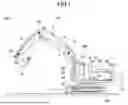


Sources:
- United States Patent and Trademark Office - verify current appl. status at the USPTO↗
Similar patent applications:
- » 20090198367
Work machining apparatus control program and work machining apparatus control device for executing the control program - » 20200347581
Control apparatus, work machine, control method, and computer readable storage medium - » 20200362536
Control apparatus, work machine, control method, and computer readable storage medium - » 20210286376
Control system, control apparatus, autonomous work machine, operation method of control apparatus, control method of autonomous work machine, and storage medium - » 20260176847
WORK MACHINE AND CONTROL APPARATUS FOR WORK MACHINE - » 20200363796
CONTROL APPARATUS, WORK MACHINE, AND COMPUTER-READABLE STORAGE MEDIUM - » 20210296670
Control apparatus, electric power supply apparatus, working machine, management apparatus, control method, management method, and computer-readable recording medium - » 20150135693
Engine control apparatus for work machine and engine control method thereof - » 20100218494
Pump control apparatus for hydraulic work machine, pump control method and construction machine - » 20100319903
Temperature control apparatus of working machine
Recent applications in this class:
- » 20260176844 2026-06-25
DISPLAY SYSTEM OF WORK SITE AND DISPLAY METHOD OF WORK SITE - » 20260152927 2026-06-04
SYSTEM AND METHOD FOR CONTROLLING CONSTRUCTION MACHINERY - » 20260152926 2026-06-04
PREVENTING ACCIDENTS BY ANALYZING AND BALANCING MATERIAL PILES IN INDUSTRIAL TRANSPORTATION - » 20260139457 2026-05-21
WORK VEHICLE - » 20260062894 2026-03-05
Power Feed System of Electrically Driven Construction Machine - » 20260055580 2026-02-26
SYSTEM FOR COUPLING AN IDENTIFICATION MODULE TO A WORK MACHINE ATTACHMENT - » 20260022540 2026-01-22
DETECTION SYSTEM FOR WORK SITE AND DETECTION METHOD FOR WORK SITE - » 20260022539 2026-01-22
WORKING VEHICLE AND MANAGEMENT SYSTEM TO MANAGE ATTACHMENTS - » 20260009206 2026-01-08
BLIND SPOT DISPLAY DEVICE FOR CONSTRUCTION EQUIPMENT - » 20250382775 2025-12-18
COCKPIT WARNING AND IDENTIFICATION SYSTEM