WATER OUTLET STRUCTURE AND SINK
US20260176853A1
2026-06-25
19/026,081
2025-01-16
Smart Summary: A new design for kitchen sinks includes a special water outlet structure. This structure has a box with an opening, where a spray assembly is attached. A water pipe connects to this spray assembly, allowing water to flow through. The spray assembly can be easily removed for replacement when needed. This makes it convenient to maintain and update the sink's features. 🚀 TL;DR
Abstract:
The present invention relates to the field of kitchen sinks, in particular to a water outlet structure and a sink. The water outlet structure comprises a box body, a spray assembly and a water pipe. The box body has an opening. The spray assembly is mounted at the opening. The water pipe is communicated with the spray assembly. The water pipe is mounted on the box body. The water pipe has a water outlet end and a water inlet end. The water outlet end is detachably connected to and communicated with the spray assembly. A snap-fit component is mounted in the box body. The spray assembly is in snap fit to the snap-fit component. The water outlet structure and the sink have the advantage that the spray assembly can be removed from the opening of the box body for replacement.
Applicant:
Interested in similar patents?
Get notified when new applications in this technology area are published.
Classification:
E03C1/048 » CPC main
Domestic plumbing installations for fresh water or waste water; Sinks; Plumbing installations for fresh water; Water-basin installations specially adapted to wash-basins or baths supplying water through two or more openings around or along one side of the water-basin
Description
CROSS-REFERENCE TO RELATED APPLICATIONS
This is a U.S. patent application which claims the priority and benefit of Chinese Patent Application Number 202423214417.6, filed on Dec. 25, 2024, the disclosure of which is incorporated herein by reference in its entirety.
TECHNICAL FIELD
The present invention relates to the field of kitchen sinks, in particular to a water outlet structure and a sink.
BACKGROUND
Mounting a rainfall water outlet structure on a kitchen sink has the advantage of being convenient to spray and clean. The principle of the rainfall water outlet structure is to mount a shower head on an inner wall of a sink, spray water to a space in the sink, and place items that need to be cleaned in the sink, thereby being capable of conducting quick spraying and rinsing.
Existing rainfall water outlet structures have the problems that nozzles are easily clogged, and shower heads are difficult to remove from sinks, causing the rainfall water outlet structures to easily fail.
SUMMARY
In order to solve the above technical problems, the purpose of the present invention is to provide a water outlet structure, a spray assembly of which is easy to disassemble and replace, thus solving the problem of clogging; and to provide a sink, a spray assembly of which is easy to replace after being clogged.
The technical solutions used in the present invention to solve the problems are: a water outlet structure, comprising:
-
- a box body, a spray assembly and a water pipe. The box body has an opening. The spray assembly is mounted at the opening. The water pipe is communicated with the spray assembly. The water pipe is mounted on the box body. The water pipe has a water outlet end and a water inlet end. The water outlet end is detachably connected to and communicated with the spray assembly. A snap-fit component is mounted in the box body. The spray assembly is in snap fit to the snap-fit component.
As an improved technical solution, one end of the spray assembly is in snap fit to the snap-fit component. The snap-fit component is a press-type latch. The other end of the spray assembly is detachably connected to the box body.
As an improved technical solution, a mounting column is provided in the box body. A mounting groove is provided on the mounting column. A U-shaped clip is provided on the spray assembly. The U-shaped clip is in snap fit to the mounting groove.
As an improved technical solution, the mounting groove is in clearance fit with the U-shaped clip. A thickness of an outer end of the U-shaped clip is less than a thickness of an inner end of the U-shaped clip.
As an improved technical solution, a mounting pipe is provided at an inner end of the water pipe. A mounting hole extending front and back is provided in the mounting pipe. The mounting hole is communicated with the water pipe. A connecting pipe section is provided at a rear end of the spray assembly. A water outlet notch is provided on a side wall of the connecting pipe section. The connecting pipe section is connected to the mounting hole in an inserted mode. The water outlet notch is communicated with the water pipe.
As an improved technical solution, a first mounting seat, a second mounting seat and a third mounting seat are provided on an inner wall of the box body. The snap-fit component is mounted on the first mounting seat. The mounting pipe is connected to the second mounting seat in an inserted mode. The mounting column is mounted on the third mounting seat.
As an improved technical solution, a through hole is provided on the box body. The water inlet end passes through the through hole and is rotatably connected to the through hole. A middle portion of the water pipe is a hose.
As an improved technical solution, the spray assembly comprises a front cover plate, a nozzle plate and a rear cover plate. The front cover plate is connected to the rear cover plate in a sealed manner. Several protruding spray pipes are provided on the nozzle plate. The spray pipes pass through the front cover plate.
A sink comprises the water outlet structure, and further comprises a sink body. A through groove is provided on the sink body. A flange protruding backwards is provided in the through groove. An edge of the box body is connected to an outer wall of the sink body in a pressed-against mode and is provided at a periphery of the flange. The spray assembly is provided in the through groove.
The beneficial effects of the present invention are that: since the spray assembly is in snap fit to the snap-fit component, and the water outlet end is detachably connected to and communicated with the spray assembly, the spray assembly can be removed from the opening of the box body for replacement, thereby preventing a rainfall function from being unusable after the spray assembly is clogged.
BRIEF DESCRIPTION OF DRAWINGS
The present invention will be further explained below in conjunction with the description of the accompanying drawings and specific embodiments.
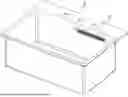
FIG. 1 is a perspective view of a preferred implementation of a sink of the present invention;
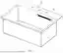
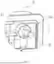
FIG. 2 is a perspective cross-sectional view of FIG. 1;
FIG. 3 is an enlarged view of part A in FIG. 2;
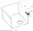
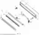
FIG. 4 is an exploded view of a water outlet structure of the present invention;
FIG. 5 is an enlarged view of part C in FIG. 4;
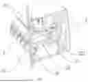
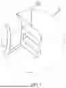
FIG. 6 is a perspective view of a box body;
FIG. 7 is an enlarged view of Part B in FIG. 6.
-
- In the drawings: 1—box body, 11—opening, 12—mounting column, 121—mounting groove, 13—first mounting seat, 14—second mounting seat, 15—third mounting seat, 16—through hole, 2—spray assembly, 21—U-shaped clip, 22—connecting pipe section, 221—water outlet notch, 23—front cover plate, 24—nozzle plate, 241—spray pipe, 25—rear cover plate, 3—water pipe, 31—water outlet end, 32—water inlet end, 33—mounting pipe, 331—mounting hole, 4—snap-fit component, 5—sink body, 51—through groove, 52—flange.
DESCRIPTION OF EMBODIMENTS
This section will describe the specific embodiments of the present invention in detail. The preferred embodiments of the present invention are shown in the accompanying drawings. The function of the accompanying drawings is to supplement the statement of the text part of the description with graphics, so that people can intuitively and vividly understand each technical feature and overall technical solution of the present invention. However, the accompanying drawings shall not be construed as a limitation to the protection scope of the present invention.
In the statement of the present invention, it should be understood that orientation statements, such as orientation or position relationships indicated by up, down, front, back, left, right, etc., are based on the orientation or position relationships shown in the accompanying drawings and are only to facilitate the statement of the present invention and simplify the statement, rather than indicate or imply that the device or element referred to must have a specific orientation, be constructed and operate in a specific orientation, and therefore should not be understood as a limitation to the present invention.
In the statement of the present invention, “several” means one or more, “a plurality of” means two or more, “greater than”, “less than”, and “more than”, etc. are understood to exclude the original number, and above, below, within, etc. are understood to include the original number. If there is a statement of first and second, it is only for the purpose of distinguishing technical features, and cannot be understood as indicating or implying the relative importance or implicitly indicating the number of indicated technical features or implicitly indicating the order of indicated technical features.
In the statement of the present invention, unless otherwise explicitly specified, words such as setting, installation, and connection should be understood in a broad sense. Those skilled in the art can reasonably determine the specific meanings of the above words in the present invention in combination with the specific content of the technical solution.
Referring to FIG. 3 to FIG. 7, a water outlet structure, comprising:
-
- a box body 1, a spray assembly 2 and a water pipe 3, the box body 1 having an opening 11, the spray assembly 2 being mounted at the opening 11, the water pipe 3 being communicated with the spray assembly 2, the water pipe 3 being mounted on the box body 1, the water pipe 3 having a water outlet end 31 and a water inlet end 32, the water outlet end 31 is detachably connected to and communicated with the spray assembly 2, a snap-fit component 4 being mounted in the box body 1, and the spray assembly 2 being in snap fit to the snap-fit component 4.
Since the spray assembly 2 is in snap fit to the snap-fit component 4, and the water outlet end 31 is detachably connected to and communicated with the spray assembly 2, the spray assembly 2 can be removed from the opening 11 of the box body 1 for replacement, thereby preventing a rainfall function from being unusable after the spray assembly 2 is clogged.
As a preferred embodiment, one end of the spray assembly 2 is in snap fit to the snap-fit component 4, the snap-fit component 4 is a press-type latch, and the other end of the spray assembly 2 is detachably connected to the box body 1. The press-type latch is a common part that can be purchased on the market, and is often used in a trash bin lid. By pressing the trash bin lid, a state of the press-type latch can be switched, so as to lock or open the trash bin lid. In the present invention, by pressing one end of the spray assembly 2, one end of the spray assembly 2 is capable of popping out like the trash bin lid, and the other end of the spray assembly 2 is capable of being removed from the box body 1, which makes it very convenient to replace the spray assembly 2.
As a preferred embodiment, a mounting column 12 is provided in the box body 1. A mounting groove 121 is provided on the mounting column 12. A U-shaped clip 21 is provided on the spray assembly 2. The U-shaped clip 21 is in snap fit to the mounting groove 121. In this implementation, the detachable connection between the other end of the spray assembly 2 and the box body 1 is capable of being implemented.
As a preferred embodiment, the mounting groove 121 is in clearance fit with the U-shaped clip 21. A thickness of an outer end of the U-shaped clip 21 is less than a thickness of an inner end of the U-shaped clip. In this implementation, the connection between the spray assembly 2 and the box body 1 is relatively flexible.
As a preferred embodiment, a mounting pipe 33 is provided at an inner end of the water pipe 3. A mounting hole 331 extending front and back is provided in the mounting pipe 33. The mounting hole 331 is communicated with the water pipe 3. A connecting pipe section 22 is provided at a rear end of the spray assembly 2. A water outlet notch 221 is provided on a side wall of the connecting pipe section 22. The connecting pipe section 22 is connected to the mounting hole 331 in an inserted mode. The water outlet notch 221 is communicated with the water pipe 3.
As a preferred embodiment, a first mounting seat 13, a second mounting seat 14 and a third mounting seat 15 are provided on an inner wall of the box body 1. The snap-fit component 4 is mounted on the first mounting seat 13. The mounting pipe 33 is connected to the second mounting seat 14 in an inserted mode. The mounting column 12 is mounted on the third mounting seat 15.
As a preferred embodiment, a through hole 16 is provided on the box body 1. The water inlet end 32 passes through the through hole 16 and is rotatably connected to the through hole 16. A middle portion of the water pipe 3 is a hose. During the process of replacing the spray assembly 2, the water pipe 3 can deform or move along with the spray assembly 2, which makes it convenient to replace the spray assembly 2.
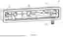
As a preferred embodiment, the spray assembly 2 comprises a front cover plate 23, a nozzle plate 24 and a rear cover plate 25. The front cover plate 23 is connected to the rear cover plate 25 in a sealed manner. Several protruding spray pipes 241 are provided on the nozzle plate 24. The spray pipes 241 pass through the front cover plate 23. Water in the water pipe 3 enters a space between the front cover plate 23 and the rear cover plate 25, and is sprayed out through the spray pipes 241 to form a rainfall effect.
Referring to FIG. 1 and FIG. 2, the present invention further provides a sink, which comprises the water outlet structure, and further comprises a sink body 5. A through groove 51 is provided on the sink body 5. A flange 52 protruding backwards is provided in the through groove 51. An edge of the box body 1 is connected to an outer wall of the sink body 5 in a pressed-against mode and is provided at a periphery of the flange 52. The spray assembly 2 is provided in the through groove 51. By pressing the spray assembly 2, the spray assembly 2 can directly pop out from the through groove 51, while the box body 1 is always fixed onto the sink body 5.
The above are only preferred embodiments of the present invention, and are not intended to limit the patent scope of the present invention. Under the inventive concept of the present invention, equivalent structural transformations made using the contents of the description and drawings of the present invention, or directly or indirectly used in other relevant technical fields are all included in the patent protection scope of the present invention.
Claims
What is claimed is:1. A water outlet structure, comprising a box body (1), a spray assembly (2) and a water pipe (3), the box body (1) having an opening (11), the spray assembly (2) being mounted at the opening (11), the water pipe (3) being communicated with the spray assembly (2), and the water pipe (3) being mounted on the box body (1),
wherein
the water pipe (3) has a water outlet end (31) and a water inlet end (32), the water outlet end (31) is detachably connected to and communicated with the spray assembly (2),
a snap-fit component (4) is mounted in the box body (1), and the spray assembly (2) is in snap fit to the snap-fit component (4).
2. The water outlet structure according to claim 1, wherein
one end of the spray assembly (2) is in snap fit to the snap-fit component (4), the snap-fit component (4) is a press-type latch, and the other end of the spray assembly (2) is detachably connected to the box body (1).
3. The water outlet structure according to claim 2, wherein
a mounting column (12) is provided in the box body (1), a mounting groove (121) is provided on the mounting column (12), a U-shaped clip (21) is provided on the spray assembly (2), and the U-shaped clip (21) is in snap fit to the mounting groove (121).
4. The water outlet structure according to claim 3, wherein
the mounting groove (121) is in clearance fit with the U-shaped clip (21), and a thickness of an outer end of the U-shaped clip (21) is less than a thickness of an inner end of the U-shaped clip.
5. The water outlet structure according to claim 1, wherein
a mounting pipe (33) is provided at an inner end of the water pipe (3), a mounting hole (331) extending front and back is provided in the mounting pipe (33), the mounting hole (331) is communicated with the water pipe (3), a connecting pipe section (22) is provided at a rear end of the spray assembly (2), a water outlet notch (221) is provided on a side wall of the connecting pipe section (22), the connecting pipe section (22) is connected to the mounting hole (331) in an inserted mode, and the water outlet notch (221) is communicated with the water pipe (3).
6. The water outlet structure according to claim 5, wherein
a first mounting seat (13), a second mounting seat (14) and a third mounting seat (15) are provided on an inner wall of the box body (1), the snap-fit component (4) is mounted on the first mounting seat (13), the mounting pipe (33) is connected to the second mounting seat (14) in an inserted mode, and the mounting column (12) is mounted on the third mounting seat (15).
7. The water outlet structure according to claim 1, wherein
a through hole (16) is provided on the box body (1), the water inlet end (32) passes through the through hole (16) and is rotatably connected to the through hole (16), and a middle portion of the water pipe (3) is a hose.
8. The water outlet structure according to claim 1, wherein
the spray assembly (2) comprises a front cover plate (23), a nozzle plate (24) and a rear cover plate (25), the front cover plate (23) is connected to the rear cover plate (25) in a sealed manner, several protruding spray pipes (241) are provided on the nozzle plate (24), and the spray pipes (241) pass through the front cover plate (23).
9. A sink, comprising the water outlet structure according to claim 1, and further comprising a sink body (5), wherein
a through groove (51) is provided on the sink body (5), a flange (52) protruding backwards is provided in the through groove (51), an edge of the box body (1) is connected to an outer wall of the sink body (5) in a pressed-against mode and is provided at a periphery of the flange (52), and the spray assembly (2) is provided in the through groove (51).
Images & Drawings included:
Sources:
- United States Patent and Trademark Office - verify current appl. status at the USPTO↗
Recent applications in this class:
- » 20250012060 2025-01-09
SINK WITH INTEGRATED RINSE FEATURE - » 20240271399 2024-08-15
FAUCET - » 20240068212 2024-02-29
RINSING LAVATORY - » 20230340766 2023-10-26
Sink with integrated rinse feature - » 20230332387 2023-10-19
WATER OUTLET DEVICE - » 20230250619 2023-08-10
Rinsing channel device for a basin - » 20230011411 2023-01-12
SELF CLEANING SINK BASINS - » 20220298765 2022-09-22
FOUNTAIN-TYPE WASH BASIN - » 20220025620 2022-01-27
Sink with integrated rinse feature - » 20200362547 2020-11-19
Self cleaning sink