INTERLOCKING ROOF TILE SYSTEM WITH WATER GROOVES
US20260176871A1
2026-06-25
18/987,226
2024-12-19
Smart Summary: An interlocking roof tile system has been created to improve how water drains off roofs. Each tile has special parts on both sides that connect to other tiles securely. One side has a collar on top that helps manage water flow, while the other side has a collar on the bottom. There are tiny channels, called capillaries, that help direct water from one tile to the next. This design helps prevent water from pooling on the roof, making it more effective at keeping the building dry. 🚀 TL;DR
Abstract:
Provided herein is an interlocking roof tile system designed to enhance water drainage. The roof tile sheet as described herein may include a first side connection member and a second side connection member on a substantially opposite side as the first side connection member. The first side connection member may include an upper extending collar positioned on a top side of the roof tile sheet and a capillary drainage system comprising at least one capillary. The second side connection member may include a lower extending collar positioned on a bottom side of the roof tile sheet. The at least one capillary may be configured to receive water flowing from an adjacent roof tile sheet.
Applicant:
Interested in similar patents?
Get notified when new applications in this technology area are published.
Classification:
E04D1/2949 » CPC main
Roof covering by making use of tiles, slates, shingles, or other small roofing elements; Means for connecting or fastening adjacent roofing elements by interfitted sections having joints with fluid-handling feature, e.g. a fluid channel for draining
E04D1/265 » CPC further
Roof covering by making use of tiles, slates, shingles, or other small roofing elements; Strip-shaped roofing elements simulating a repetitive pattern, e.g. appearing as a row of shingles the roofing elements being rigid, e.g. made of metal, wood or concrete
E04D1/00 IPC
Roof covering by making use of tiles, slates, shingles, or other small roofing elements
E04D1/26 IPC
Roof covering by making use of tiles, slates, shingles, or other small roofing elements Strip-shaped roofing elements simulating a repetitive pattern, e.g. appearing as a row of shingles
Description
FIELD OF INVENTION
The present invention relates generally to a roof tile system. More specifically, the invention relates to an interlocking roof tile system with water grooves.
BACKGROUND OF INVENTION
Roof tiles are commonly used in the building and construction industry to provide buildings with increased weather protection, functionality, durability, and/or aesthetics. Roof tiles are made of various different materials. Roof tiles include varying designs for energy efficiency, weather resistance, reduction in weight, and durability.
Roofs include connections to water drainage systems to drain water from the roof in order to prevent water from collecting and leaking into a building. However, existing roofs include a portion at which water collects and cannot exit. Connection points between the roof tiles allow for water to collect, leading to deterioration of the roof tiles and potential leakage of the roof. As such, a need exists for roof tiles that provide a pathway for water at or near connection points to aid in preventing collection of water and draining water from the roof of a building.
SUMMARY OF INVENTION
The present invention overcomes many of the shortcomings and limitations of the prior art devices discussed above. The invention described herein includes several embodiments of an interlocking roof tile system with water grooves.
Provided herein is a roof tile system designed to enhance water drainage. The roof tile system as described herein addresses the need in the art for roof tiles that provide a pathway for water at or near connection points to aid in preventing collection of water and draining water from the roof of a building. The roof tile system may include several roof tile sheets interlocking with one another. Each roof tile sheet may include an upper edge that engages with a lower edge of another roof tile sheet to aid in creating an interlocking system.
Each roof tile sheet may also incorporate connection members on each of its sides, which can engage with corresponding members on adjacent sheets. The connection members may include a capillary drainage system, which may include multiple capillaries or tunnel-like pathways that direct water away from the roof. This configuration may aid in preventing water accumulation at the connection points of the roof tile sheets. The water may drain from the multiple capillaries toward a gutter or other drainage system on the building.
BRIEF DESCRIPTION OF DRAWINGS
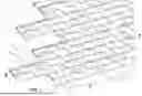
FIG. 1 is a perspective view of a roof tile system constructed of several interlocking roof tile sheets constructed according to the teachings of the present application;
FIG. 2 is a cross-sectional view of the roof tile system of FIG. 1 taken across line 2-2 of FIG. 1;
FIG. 3 is a top view of an interlocking roof tile sheet constructed according to the teachings of the present application;
FIG. 4 is a bottom view of the interlocking roof tile sheet of FIG. 3;
FIG. 5 is a cross-sectional view of the roof tile system of FIG. 1 taken across line 5-5 of FIG. 1; and
FIG. 6 is an enlarged perspective view of the roof tile system of FIG. 1.
While the disclosure is susceptible to various modifications and alternative forms, a specific embodiment thereof is shown by way of example in the drawings and will herein be described in detail. It should be understood, however, that the drawings and detailed description presented herein are not intended to limit the disclosure to the particular embodiment disclosed, but to the contrary, the intention is to cover all modifications, equivalents, and alternatives falling within the spirit and scope of the present disclosure as defined by the appended claims.
DETAILED DESCRIPTION
The invention will now be described with reference to the drawing figures, in which like reference numerals refer to like parts throughout. For purposes of clarity in illustrating the characteristics of the present invention, proportional relationships of the elements have not necessarily been maintained in the drawing figures.
Turning first to FIG. 1, a roof tile system 1 may include several interlocking roof tile sheets 5. A first roof tile sheet 5a may be connected via its: upper portion 10 to a second roof tile sheet 5b; first side portion 15 to a third roof tile sheet 5c; lower portion 20 to a fourth roof tile sheet 5d; and second side portion 25 to a fifth roof tile sheet 5e. It should be understood that references to roof tile sheets 5a-5e may refer to any of the other roof tile sheets 5a-5e, and that such references are for exemplary purposes only. The roof tile sheets 5 may be positioned in a brick-like, offset configuration, such that the upper portion 10 and the lower portion 20 connect to more than one of the roof tile sheets 5. The configuration and interlocking manner of the roof tile sheets 5 may encourage the flow of water in the direction as illustrated by arrow 30.
The roof tile sheets 5 may interlock in a manner as described herein to create an interlocking system, as illustrated by the roof tile system 1. According to various embodiments, the roof tile sheets 5 may be laid horizontally, such that the distance between the first and second side portions 15, 25 of each roof tile sheet 5 is greater than the distance between the upper and lower portions 10, 20 of each roof tile sheet 5. The roof tile sheets 5 may be laid in any suitable manner or in any manner known in the art, and the roof tile sheets 5 may be made of any suitable material. A top side 35 of the roof tile sheets 5 may include various designs, and in one embodiment, the top side 35 is designed to look like slate, asphalt, wood, or a standard roofing shingle. When the roof tile sheet 5 is installed, the top side 35 may be exposed to the elements (e.g., rain, sleet, snow).
Turning to FIG. 2 to illustrate the connection between the lower portion 20 and the upper portion 10, the lower portion 20 of the second roof tile sheet 5b may connect or be coupled to the upper portion 10 of the first roof tile sheet 5a. More particularly, a lower edge 40 of the lower portion 20 of the second roof tile sheet 5b may include a lower interlocking member 45 that may be substantially U-shaped. The lower edge 40 may include a cavity 50 formed by the lower interlocking member 45, and the cavity 50 may be configured to receive an elongate member 55 positioned on an upper edge 60 of the upper portion 10 of the first roof tile sheet 5a. The cavity 50 may be sized such that the elongate member 55 can fit into the cavity 50 and be held in place when engaged.
FIGS. 3 and 4 illustrate the connection between the first side portion 15 and the second side portion 25. As illustrated in FIG. 3, the top side 35 may include a first side connection member 65 positioned at or near the first side portion 15 of the first roof tile sheet 5a. The first side connection member 65 may be in any suitable position and does not necessarily have to be at the first side portion 15; as one example, the first side connection member 65 may be positioned at or near the second side portion 25.
The first side connection member 65 may include a capillary drainage system 70 formed on the top side 35 of the first roof tile sheet 5a. The capillary drainage system 70 may aid in preventing water from collecting in the area in which roof tile sheets 5 attach via the first side portion 15 and the second side portion 25. The capillary drainage system 70 may include multiple capillaries 75, which may be formed as tunnel-like pathways. Water may flow into the multiple capillaries 75 and in a downward direction, away from the roof system 1, when on a roof of a building.
The first side connection member 65 may also include an upper extending collar 80 for attaching or connecting it to another, adjacent roof tile sheet (e.g., the third roof tile sheet 5c). The upper extending collar 80 may include an upper arm portion 85 that extends upward from the top side 35 of the first roof tile sheet 5a and inward toward the second side portion 25 of the first roof tile sheet 5a. In one embodiment, the extension of the upper arm portion 85 may form an upper cavity 90, which may be configured to attach to the third roof tile sheet 5c.
More particularly, as provided in FIG. 4, the upper cavity 90 of the upper extending collar 80 may receive a second side connection member 95 of the third roof tile sheet 5c. The second side connection member 95 may be positioned on a bottom side 100 of the third roof tile sheet 5c and on the second side portion 25 of the third roof tile sheet 5c. The second side connection member 95 may include a lower extending collar 105 for attaching or connecting it to another roof tile sheet (e.g., the first roof tile sheet 5a). The lower extending collar 105 may include a lower arm portion 110 that extends upward from the bottom side 100 of the third roof tile sheet 5c and inward toward the first side portion 15 of the third roof tile sheet 5c. In one embodiment, the extension of the lower arm portion 110 may form a lower cavity 115, which may be configured to attached to upper arm portion 85 of the first roof tile sheet 5a. Each of the roof tile sheets 5 may include the first side connection member 65 and the second side connection member 95 such that it may attach to adjacent roof tile sheets 5 on each of the first and second side portions 15, 25.
Turning now to FIG. 5 to illustrate the connection between the first and second side connection members 65, 95, the first side connection member 65 of the first roof tile sheet 5a may engage with the second side connection member 95 of the third roof tile sheet 5c. The upper arm portion 85 of the first side connection member 65 may slide into the lower cavity 115 of the second side connection member 95. The lower cavity 115 may be shaped and sized such that the upper arm portion 85 fits into the lower cavity 115. The lower arm portion 110 of the second side connection member 95 may slide into the upper cavity 90 of the first side connection member. The upper cavity 90 may be shaped and sized such that the lower arm portion 110 fits into the upper cavity 90. When connected, the upper arm portion 85 may be held in place by the lower cavity 115, and the lower arm portion 110 may be held in place by the upper cavity 90. When the first roof tile sheet 5a is engaged with and connected to the third roof tile sheet 5c, the capillary drainage system 70 is formed to encourage water to flow away from the first and third roof tile sheets 5a, 5c. More particularly, the first side connection member 65 may engage with the second side connection member 95, such that the capillary drainage system 70 is formed, and water flows through the multiple capillaries 75 and away from the first and third roof tile sheets 5a, 5c.
When water is present and the roof tile system 1 is installed, water may flow from the third roof tile sheet 5c along the second side connection member 95 into the capillary drainage system 70 of the first roof tile sheet 5a and multiple capillaries 75 of the first side connection member 65. The water may flow in a direction as illustrated by arrows 120. The multiple capillaries 75 may encourage water to flow in a downward direction, and ultimately, toward a gutter or other drainage system on a building.
As illustrated in FIG. 6, and as one example, water may flow from the first roof tile sheet 5a of the roof tile system 1 toward the capillary drainage system 70 nearest the water, and from there, the water may flow in a downward direction (illustrated by arrow 125) toward fourth roof tile sheet 5d. This flow of water may cause the water to ultimately be fed into a gutter or other drainage system of the building.
As is evident from the foregoing description, certain aspects of the present invention are not limited by the particular details of the examples illustrated herein, and it is therefore contemplated that other modifications, applications, variations, or equivalents thereof, will occur to those skilled in the art. Many such changes, modifications, variations, and other uses and applications of the present constructions will, however, become apparent to those skilled in the art after considering the specification and the accompanying drawings. In addition, unless mention was made above to the contrary, it should be noted that all of the accompanying drawings are not to scale. All such changes, modifications, variations, and other uses and applications which do not depart from the spirit and scope of the present inventions are deemed to be covered by the inventions which are limited only by the claims which follow.
Claims
1. A roof tile sheet comprising:
a first side connection member comprising an upper extending collar positioned on a top side of the roof tile sheet and a capillary drainage system comprising at least one capillary; and
a second side connection member on a substantially opposite side as the first side connection member, wherein the second side connection member comprises a lower extending collar positioned on a bottom side of the roof tile sheet;
wherein the at least one capillary is configured to receive water flowing from an adjacent roof tile sheet.
2. The roof tile sheet of claim 1, further comprising:
a lower portion comprising a lower edge;
an upper portion comprising an upper edge;
wherein at least one of:
the lower edge of the lower portion engages with an upper edge of an adjacent upper portion of the adjacent roof tile sheet to create an interlocking roof tile system; and
the upper edge of the upper portion engages with a lower edge of an adjacent lower portion of the adjacent roof tile sheet to create an interlocking roof tile system.
3. The roof tile sheet of claim 2, wherein the lower edge comprises a lower interlocking member forming a cavity, and wherein the upper edge comprises an elongate member.
4. The roof tile sheet of claim 3, wherein at least one of:
the cavity receives an adjacent elongate member of the adjacent roof tile sheet to create an interlocking roof tile system; and
the elongate member is received into an adjacent cavity of the adjacent roof tile sheet to create an interlocking roof tile system.
5. The roof tile sheet of claim 1, wherein the upper extending collar comprises an upper arm portion forming an upper cavity, and wherein the lower extending collar comprises a lower arm portion forming a lower cavity.
6. The roof tile sheet of claim 5, wherein the upper cavity receives a lower arm portion of the adjacent roof tile sheet to create an interlocking roof tile system.
7. The roof tile sheet of claim 5, wherein the lower cavity receives an upper arm portion of the adjacent roof tile sheet to create an interlocking roof tile system.
8. The roof tile sheet of claim 1, wherein a top side of the roof tile sheet includes a design, and wherein the design is at least one of an asphalt shingle, a wood shingle, and a slate shingle.
9. A roof tile system comprising:
a first roof tile sheet and a second roof tile sheet, each comprising:
a first side connection member comprising an upper extending collar positioned on
a top side of each of the first and second roof tile sheet and a capillary drainage system comprising at least one capillary; and
a second side connection member on a substantially opposite side as the first side connection member, wherein the second side connection member comprises a lower extending collar positioned on a bottom side of each of the first and second roof tile sheet;
wherein the at least one capillary is configured to receive water flowing from an adjacent roof tile sheet; and
wherein the first roof tile sheet and the second roof tile sheet are interlockable with one another.
10. The roof tile system of claim 9, wherein the first roof tile sheet and the second roof tile sheet each comprise:
a lower portion comprising a lower edge;
an upper portion comprising an upper edge;
wherein at least one of:
the lower edge of the first roof tile sheet engages with the upper edge of the second roof tile sheet; and
the upper edge of the first roof tile sheet engages with the lower edge of the second roof tile sheet.
11. The roof tile system of claim 10, wherein:
the lower edge of each of the first roof tile sheet and the second roof tile sheet comprises a lower interlocking member forming a cavity; and
the upper edge of each of the first roof tile sheet and the second roof tile sheet comprises an elongate member.
12. The roof tile system of claim 11, wherein at least one of:
the cavity of the first roof tile sheet receives the elongate member of the second roof tile sheet; and
the cavity of the second roof tile sheet receives the elongate member of the first roof tile sheet.
13. The roof tile system of claim 9, wherein:
the upper extending collar of each of the first roof tile sheet and the second roof tile sheet comprises an upper arm portion forming an upper cavity; and
the lower extending collar of each of the first roof tile sheet and the second roof tile sheet comprises a lower arm portion forming a lower cavity.
14. The roof tile system of claim 13, wherein the upper cavity of the first roof tile sheet receives the lower arm portion of the second roof tile sheet.
15. The roof tile system of claim 13, wherein the lower cavity of the first roof tile sheet receives the upper arm portion of the second roof tile sheet.
16. The roof tile system of claim 9, wherein a top side of each of the first roof tile sheet and the second roof tile sheet includes a design, and wherein the design is at least one of an asphalt shingle, a wood shingle, and a slate shingle.
17. A roof tile sheet comprising:
a first side connection member comprising a capillary drainage system comprising at least one capillary; and
a second side connection member on a substantially opposite side as the first side connection member configured to engage with the first side connection member.
18. The roof tile sheet of claim 17, wherein the at least one capillary is configured to receive water flowing from an adjacent roof tile sheet.
19. The roof tile sheet of claim 17, wherein:
the first side connection member further comprises an upper extending collar positioned on a top side of the roof tile sheet;
the second side connection member comprises a lower extending collar positioned on a bottom side of the roof tile sheet; and
the upper extending collar of the roof tile sheet engages with a lower extending collar of an adjacent roof tile sheet.
20. The roof tile sheet of claim 17, wherein the roof tile sheet interlocks with an adjacent roof tile sheet.
Images & Drawings included:


Sources:
- United States Patent and Trademark Office - verify current appl. status at the USPTO↗
Recent applications in this class:
- » 20130276397 2013-10-24
Leak Locating Shingle - » 20120102876 2012-05-03
Method of tiling a roof with interlocking tiles employing an adjustable rain lock - » 20110041445 2011-02-24
Shingle with interlocking water diverter tabs - » 20090249729 2009-10-08
Interlocking tiles employing adjustable rain lock - » 20080098684 2008-05-01
Shingle with interlocking water diverter tabs - » 20050210807 2005-09-29
Shingle with interlocking water diverter tabs