POST ASSEMBLY WITH VERTICAL COMPRESSION CHANNEL
US20260176889A1
2026-06-25
19/429,160
2025-12-22
Smart Summary: A post assembly consists of a vertical post with a flange on one side and a web that sticks out from it. On the opposite side, there is another flange that connects to the web. A special channel is designed to fit between these two flanges. This channel has flat sides that align with the flanges and includes extensions that are slightly angled to fit snugly between them. The design allows for adjustments to create a specific architectural shape or crease. 🚀 TL;DR
Abstract:
A post assembly can include a post member having a first flange and a web, where the web extends at least generally perpendicularly from the first flange. The post assembly can also include a second flange for connecting to the web of the post member opposite the first flange. The post assembly can also include a channel configured to be captured by the first flange and the second flange. In some embodiments, the channel has opposing faces that are generally coplanar with faces of the first and second flanges. Further, the channel can include opposing extensions generally parallel to the opposing faces and offset (e.g., tapered) from the opposing faces to be captured between the first flange and the second flange. The opposing extensions can be sized so that the channel can be adjusted with respect to the post member and the second flange to form an architectural crease.
Applicant:
Interested in similar patents?
Get notified when new applications in this technology area are published.
Classification:
E04H17/21 » CPC main
Fencing, e.g. fences, enclosures, corrals; Fences constructed of rigid elements, e.g. with additional wire fillings or with posts; Posts therefor with hollow cross sections
E04H17/1465 » CPC further
Fencing, e.g. fences, enclosures, corrals; Fences constructed of rigid elements, e.g. with additional wire fillings or with posts; Post-and-rail fences, e.g. without vertical cross-members; Details of connections between rails and posts the rails being supported within blind or through holes of the posts
E04H17/20 IPC
Fencing, e.g. fences, enclosures, corrals; Fences constructed of rigid elements, e.g. with additional wire fillings or with posts Posts therefor
E04H17/14 IPC
Fencing, e.g. fences, enclosures, corrals Fences constructed of rigid elements, e.g. with additional wire fillings or with posts
Description
CROSS-REFERENCE TO RELATED APPLICATIONS
The present application claims the benefit under 35 U.S.C. § 119(e) of U.S. Provisional Application Ser. No. 63/738,438, filed Dec. 23, 2024, and titled “POST ASSEMBLY WITH VERTICAL COMPRESSION CHANNEL,” and U.S. Provisional Application Ser. No. 63/811,038, filed May 23, 2025, and titled “POST ASSEMBLY WITH VERTICAL COMPRESSION CHANNEL,” which are herein incorporated by reference in their entireties.
BACKGROUND
Barriers, railings, and other structures can be used to enclose an area of ground to mark a boundary, control access, and so forth.
DRAWINGS
The Detailed Description is described with reference to the accompanying figures.
The use of the same reference numbers in different instances in the description and the figures may indicate similar or identical items.
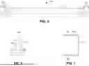
FIG. 1 is a front elevation view illustrating a post member including a first flange and a web for a post assembly in accordance with example embodiments of the present disclosure.
FIG. 2 is a front elevation view of a second flange for a post assembly in accordance with example embodiments of the present disclosure.
FIG. 3 is a front elevation view illustrating a mechanical screening assembly including a panel mounted between adjacent post assemblies in accordance with example embodiments of the present disclosure.
FIG. 4 is a side elevation view of the panel illustrated in FIG. 3.
FIG. 5 is a top plan view of the mechanical screening assembly illustrated in FIG. 3.
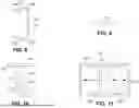
FIG. 6 is a top plan view of a post member including a first flange and a web, such as the post member illustrated in FIG. 1, in accordance with example embodiments of the present disclosure.
FIG. 7 is a side view of a C-channel for a panel of a mechanical screening assembly, such as the mechanical screening assembly illustrated in FIG. 3, in accordance with example embodiments of the present disclosure.
FIG. 8 is a is a top plan view of a vertical compression channel for a panel of a mechanical screening assembly, such as the mechanical screening assembly illustrated in FIG. 3, in accordance with example embodiments of the present disclosure.
FIG. 9 is a top plan view of a second flange, such as the second flange illustrated in FIG. 2, in accordance with example embodiments of the present disclosure.
FIG. 10 is a top plan view of a post assembly including a post member having a first flange and a web, and a second flange in accordance with example embodiments of the present disclosure.
FIG. 11 is a top plan view illustrating a post assembly with vertical compression channels captured by first and second flanges of the post assembly in accordance with example embodiments of the present disclosure.
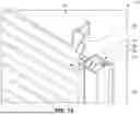
FIG. 12 is a partial cross-sectional isometric view illustrating a mechanical screening assembly including a panel with a vertical compression channel captured by first and second flanges of a post assembly in accordance with example embodiments of the present disclosure.
FIG. 13 is another partial cross-sectional isometric view illustrating a mechanical screening assembly including a panel with a vertical compression channel captured by first and second flanges of a post assembly in accordance with example embodiments of the present disclosure.
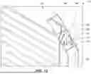
FIG. 14 is an exploded isometric view illustrating a mechanical screening assembly, such as the mechanical screening assembly shown in FIG. 3, in accordance with example embodiments of the present disclosure.
FIG. 15 is another exploded isometric view of the mechanical screening assembly illustrated in FIG. 14.
FIG. 16 is a top plan view illustrating a post member including a first flange and a web, a second flange, and a post in accordance with example embodiments of the present disclosure.
FIG. 17 is a top plan view of the first flange and the web illustrated in FIG. 16.
FIG. 18 is an elevation view of the first flange and the web illustrated in FIG. 16.
FIG. 19 is a top plan view of the second flange illustrated in FIG. 16.
FIG. 20 is an elevation view of the second flange illustrated in FIG. 16.
FIG. 21 is a top plan view illustrating a corner post for a post assembly in accordance with example embodiments of the present disclosure.
FIG. 22 is a top plan view illustrating a flange for a post assembly in accordance with example embodiments of the present disclosure.
FIG. 23 is an isometric view illustrating a mechanical screening assembly including a panel with vertical compression channels captured by a corner post and flange of a post assembly, such as the corner post and flange illustrated in FIGS. 22 and 23, in accordance with example embodiments of the present disclosure.
FIG. 24 is a partial cross-sectional isometric view of the mechanical screening assembly illustrated in FIG. 23.
DETAILED DESCRIPTION
Aspects of the disclosure are described more fully hereinafter with reference to the accompanying drawings, which form a part hereof, and which show, by way of illustration, example features. The features can, however, be embodied in many different forms and should not be construed as limited to the combinations set forth herein; rather, these combinations are provided so that this disclosure will be thorough and complete, and will fully convey the scope. The following detailed description is, therefore, not to be taken in a limiting sense.
Referring generally to FIGS. 1 through 15, post assemblies 100 and mechanical screening assemblies 102 are described. A mechanical screening assembly 102 (sometimes referred to as a fence) includes panels 104 that are each mounted between adjacent post assemblies 100. A series of alternating panels 104 and post assemblies 100 creates a mechanical barrier. For example, the panels 104 can each include infill (e.g., framework such as louvers 106, wire, mesh, etc.) that creates a physical and sometimes visual barrier between opposite sides of the mechanical screening assembly 102.
As described, a post assembly 100 can include a post member 108 having a first flange 110 and a web 112, where the web 112 extends at least generally perpendicularly from the first flange 110. In this manner, the post member 108 can have a ‘T’-shaped profile. The post assembly 100 can also include a second flange 114 for connecting to the web 112 of the post member 108 opposite the first flange 110 and at least substantially parallel to the first flange 110. Together, the post member 108 and the second flange 114 can have an ‘I’-shaped profile, e.g., in the manner of an I-beam.
In some embodiments, the first flange 110 and the web 112 are integrally formed. For example, the first flange 110 and the web 112 can be formed as a single extrusion (e.g., from a metal such as aluminum). The second flange 114 can also be formed from a metal such as aluminum. For instance, the second flange 114 can be an aluminum plate. In some embodiments, the web 112 of the post member 108 has a hollow cross-sectional profile 116. The second flange 114 can define apertures 118 (e.g., countersunk through holes) for receiving fasteners 120 (e.g., stainless steel bolts, screws, etc.). The web 112 can also define apertures 122 (e.g., threaded holes) for receiving the fasteners 120 to connect the second flange 114 to the web 112 of the post member 108.
The post assembly 100 can also include a channel 124 configured to be captured by the first flange 110 and the second flange 114 when the second flange 114 is connected to the web 112 of the post member 108. The channel 124 can have a ‘C’-shaped profile. The channel 124 can also be formed from a metal such as aluminum. For instance, the channel 124 can also be an aluminum extrusion. In some embodiments, the channel 124 has a generally rectangular cross-sectional profile 126. For example, the channel 124 can have opposing faces 128 that are generally coplanar with faces 130 and 132 of the first flange 110 and the second flange 114, respectively, when the channel 124 is captured by the first flange 110 and the second flange 114.
Further, the channel 124 can include opposing extensions 134 generally parallel to the opposing faces 128 and offset (e.g., tapered) from the opposing faces 128 to be captured between the first flange 110 and the second flange 114. The opposing extensions 134 can be sized so that the channel 124 can be adjusted with respect to the post member 108 and the second flange 114 to form an architectural crease 136. In some embodiments, the channel 124 can slide up to about three-eighths of an inch (⅜″) in and out with respect to the post member 108 and the second flange 114. The channel 124 can define apertures 138 for receiving infill framework, such as the louvers 106. For example, the apertures 138 in the channel 124 can be cut into a web 140 of the channel 124 and shaped for various louvers, screens, and so forth.
The post assemblies 100 and mechanical screening assemblies 102 described herein provide a clean appearance. For example, in some embodiments, a consistent three-inch (3″) reveal is provided around each panel 104. With the infill designs included in the vertical channels 124, the mechanical screening assemblies 102 can exhibit a clean and sharp finish. Further, the mechanical screening assemblies 102 described herein can provide a two-sided, finished appearance. For example, a finished appearance is provided on both the inside and outside of the panel 104, making it appealing for courtyards, balconies, and the like.
As described, the arrangement of the post members 108, the second flanges 114, and the channels 124 allow for setting the post assemblies 100 and then installing the panels 104. The tubular ‘T’-shaped/I-beam column configuration allows an installer to set the post assemblies 100 and then remove an I-beam flange so that a panel 104 can slide in from the back side of an enclosure. The second flange 114 can then be reattached, forming an I-beam column and capturing the vertical compression channel 124 between the first flange 110 and the second flange 114 of the I-beam.
The systems, techniques, and apparatus described herein provide a forgiving system for post setting, allowing for installation variances. By providing the column and vertical panel connection with an architectural vertical seam (e.g., architectural crease 136), when post setting varies, the architectural seam width can be increased or decreased accordingly. It should also be noted that, in addition to sliding the panel toward and away from the post assemblies, vertical adjustment of the panels is also facilitated. For example, varying slopes and grades can be accounted for without special adjustments, e.g., by moving the panels 104 up and down with respect to the post assemblies 100. In some embodiments, panel installation elevations may vary at post by about negative two and one-half percent (−2.5%) to about twelve percent (12%) of the panel or post height.
The post assemblies 100 and mechanical screening assemblies 102 described herein also allow for faster install times with limited fasteners. Columns can be furnished with the removable flanges fully attached. Once installed, the flanges can be removed or loosened, and a panel 104 can slide in. In some embodiments, a raised serrated edge can be used to lock a panel 104 into a post assembly 100, not necessarily requiring additional fasteners.
The tubular ‘T’-shaped/I-beam arrangement with the vertical compression profile can provide enhanced strength. For example, in some embodiments, panel horizontal pull-out strength may exceed seven hundred (700) pounds force, e.g., when pulling the panel straight-out from the post. Panel adjustment strength vertically up or down may exceed one thousand four hundred (1400) pounds force. Further, the panels 104 can be attached to the post assemblies 100 with the use of fasteners that would otherwise extend into the panels. The compression forces used to sandwich the panels 104 at the post assemblies 100 allow for a great amount of flexibility in making vertical and horizontal adjustments.
In some embodiments, the vertical channels provide a four-inch-wide cavity that can be faced on the outside of the screening with a wide range of architectural finishes and materials. These finishes can include, but are not necessarily limited to: faux brick or stone, composite wood, vinyl, aluminum, louvered, and so forth. In some embodiments, an acoustic panel can be used that includes a back side fitted with a perforated sheet. The perforated sheet provides sound absorption, wicking, and drying of materials, and may prevent rodent access. In between decorative exterior and perforated interior sheets, the panels 104 can have structural ‘Z’-shaped horizontal rails that both support the panel weight and prevent the sheets from having an appearance of “oil-canning” or having a wavy or distorted appearance. Additional ‘Z’-shaped clips can also be included, e.g., based on panel width and size.
Referring now to FIGS. 16 through 20, additional post assemblies 100 and mechanical screening assemblies 102 are described. As previously discussed, a mechanical screening assembly 102/fence can include panels 104 mounted between adjacent post assemblies 100, where a series of alternating panels 104 and post assemblies 100 creates a mechanical barrier. As described, a post assembly 100 can include a post member 108 having a first flange 110 and a web 112, where the web 112 extends at least generally perpendicularly from the first flange 110. In this manner, the post member 108 can have a ‘T’-shaped or ‘L’-shaped profile. The post assembly 100 can also include a second flange 114 for connecting to the web 112 of the post member 108 opposite the first flange 110 and at least substantially parallel to the first flange 110. Together, the post member 108 and the second flange 114 can have an ‘I’-shaped or ‘C’-shaped profile. In embodiments, the post member 108 and the second flange 114 can be attached to a longitudinally extending post 142 having a closed (e.g., rectangular, square, circular) profile for supporting the post member 108 and the second flange 114.
The post 142 provides for mechanical screening assemblies 102 that can exceed ten feet (10′) in height, e.g., by providing a reinforcing column mount arrangement for the post member 108/first flange 110 and web 112, and the second flange 114. In some embodiments, the post 142 can be fabricated from a steel material. As described with reference to FIGS. 1 through 15, the embodiments described with reference to FIGS. 16 through 20 can provide for a clamping effect on components of a mechanical screening assembly 102. For example, as previously described, the post assembly 100 can also include a channel 124 configured to be captured by the first flange 110 and the second flange 114 when the second flange 114 is connected to the web 112 of the post member 108.
In some embodiments, the first flange 110 and the web 112 are integrally formed. For example, the first flange 110 and the web 112 can be formed as a single extrusion (e.g., from a metal such as aluminum). The second flange 114 can also be formed from a metal such as aluminum. For instance, the second flange 114 can be an aluminum plate or angle. In some embodiments, the web 112 of the post member 108 has a hollow cross-sectional profile 116. The second flange 114 can define apertures 118 (e.g., countersunk through holes) for receiving fasteners 120 (e.g., stainless steel bolts, screws, etc.). The web 112 can also define apertures 122 (e.g., threaded holes) for receiving the fasteners 120 to connect the second flange 114 to the web 112 of the post member 108. In some embodiments, the second flange 114 can have an ‘L’-shaped profile with an extension 144 that mates with a corresponding recess 146 in the post member 108. Together, the post member 108 and the second flange 114 can form a ‘C’-shaped profile.
Referring now to FIGS. 21 through 24, further post assemblies 100 and mechanical screening assemblies 102 are described. As previously discussed, a mechanical screening assembly 102/fence can include panels 104 mounted between adjacent post assemblies 100, where a series of alternating panels 104 and post assemblies 100 creates a mechanical barrier. As described, a post assembly 100 can include a post member 108 having a first flange 110 and a web 112, where the web 112 extends at least generally perpendicularly from the first flange 110. The web of the post member 108 can have a closed (e.g., rectangular, square, circular) profile. In some embodiments, the post member 108 can also include another flange 148 that extends from the post member 108 at an angle 150 (e.g., an acute angle, a right angle, an obtuse angle) from the first flange 110.
The post assembly 100 can also include a second flange 114 for connecting to the web 112 of the post member 108 opposite the first flange 110 and at an angle to the first flange 110. For example, a main body 152 of the second flange 114 is oriented at an angle of about forty-five degrees with respect to the first flange 110. Together, the post member 108 and the second flange 114 can form one or multiple ‘C’-shaped profiles. For instance, at least a portion of the second flange 114 extends at least substantially parallel to the first flange 110. Additionally, when the post member 108 includes another flange 148 that extends from the post member 108 at an angle 150 from the first flange 110, the second flange 114 can include an additional portion that extends at least substantially parallel to the additional flange 148 of the post assembly 100. In this manner, the post assembly 100 can form an outside corner profile.
As described with reference to FIGS. 1 through 20, the embodiments described with reference to FIGS. 21 through 24 can provide for a clamping effect on components of a mechanical screening assembly 102. For example, as previously described, the post assembly 100 can also include a channel 124 configured to be captured by the first flange 110 and the second flange 114 when the second flange 114 is connected to the web 112 of the post member 108. In some embodiments, the first flange 110 and the web 112 are integrally formed. For example, the first flange 110 and the web 112 can be formed as a single extrusion (e.g., from a metal such as aluminum). The second flange 114 can also be formed from a metal such as aluminum. For instance, the second flange 114 can be an aluminum angle. In some embodiments, the web 112 of the post member 108 has a hollow cross-sectional profile 116. The second flange 114 can define apertures 118 (e.g., countersunk through holes) for receiving fasteners 120 (e.g., stainless steel bolts, screws, etc.). The web 112 can also define apertures 122 (e.g., threaded holes) for receiving the fasteners 120 to connect the second flange 114 to the web 112 of the post member 108.
Although the subject matter has been described in language specific to structural features and/or process operations, it is to be understood that the subject matter defined in the appended claims is not necessarily limited to the specific features or acts described above. Rather, the specific features and acts described above are disclosed as example forms of implementing the claims.
Claims
What is claimed is:1. A post assembly comprising:
a post member having a first flange and a web, the web extending at least generally perpendicularly from the first flange;
a second flange for connecting to the web of the post member opposite the first flange and at least substantially parallel to the first flange; and
a channel configured to be captured by the first flange and the second flange when the second flange is connected to the web of the post member.
2. The post assembly as recited in claim 1, wherein the first flange and the web are integrally formed.
3. The post assembly as recited in claim 2, wherein the first flange and the web are formed as an extrusion.
4. The post assembly as recited in claim 1, wherein the web has a hollow cross-sectional profile.
5. The post assembly as recited in claim 1, wherein the second flange defines a first plurality of apertures for receiving a plurality of fasteners therethrough, and the web defines a second plurality of apertures for receiving the plurality of fasteners to connect the second flange to the web of the post member.
6. The post assembly as recited in claim 1, wherein the channel has a generally rectangular cross-sectional profile comprising:
opposing faces that are generally coplanar with faces of the first flange and the second flange when the channel is captured by the first flange and the second flange; and
opposing extensions generally parallel to the opposing faces and offset from the opposing faces to be captured between the first flange and the second flange.
7. The post assembly as recited in claim 6, wherein the opposing extensions are sized so that the channel can be adjusted with respect to the post member and the second flange to form an architectural crease.
8. The post assembly as recited in claim 1, wherein the channel defines a plurality of apertures for receiving a plurality of louvers.
9. The post assembly as recited in claim 1, further comprising a post configured to attach to the post member for supporting the post member and the second flange.
10. A post assembly comprising:
a post member having a first flange and a web, the web extending at least generally perpendicularly from the first flange;
a second flange for connecting to the web of the post member opposite the first flange and at least substantially parallel to the first flange; and
a post configured to attach to the post member for supporting the post member and the second flange.
11. The post assembly as recited in claim 10, wherein the first flange and the web are integrally formed.
12. The post assembly as recited in claim 11, wherein the first flange and the web are formed as an extrusion.
13. The post assembly as recited in claim 10, wherein the web has a hollow cross-sectional profile.
14. The post assembly as recited in claim 10, wherein the second flange defines a first plurality of apertures for receiving a plurality of fasteners therethrough, and the web defines a second plurality of apertures for receiving the plurality of fasteners to connect the second flange to the web of the post member.
15. The post assembly as recited in claim 10, further comprising a channel configured to be captured by the first flange and the second flange when the second flange is connected to the web of the post member.
16. The post assembly as recited in claim 15, wherein the channel has a generally rectangular cross-sectional profile comprising:
opposing faces that are generally coplanar with faces of the first flange and the second flange when the channel is captured by the first flange and the second flange; and
opposing extensions generally parallel to the opposing faces and offset from the opposing faces to be captured between the first flange and the second flange.
17. The post assembly as recited in claim 16, wherein the opposing extensions are sized so that the channel can be adjusted with respect to the post member and the second flange to form an architectural crease.
18. The post assembly as recited in claim 15, wherein the channel defines a plurality of apertures for receiving a plurality of louvers.
19. A post assembly comprising:
a post member having at least a first flange and a web, the web extending at least generally perpendicularly from the first flange;
a second flange for connecting to the web of the post member opposite the first flange and at an angle to the first flange, wherein at least a portion of the second flange extends at least substantially parallel to the first flange; and
a channel configured to be captured by the first flange and the second flange when the second flange is connected to the web of the post member.
20. The post assembly as recited in claim 19, wherein the angle is about forty-five degrees.
Images & Drawings included:


Sources:
- United States Patent and Trademark Office - verify current appl. status at the USPTO↗
Recent applications in this class:
- » 20260055633 2026-02-26
FENCE POST EXTENSION SYSTEM AND METHOD