TOOL CONFIGURED TO ENGAGE AN OBJECT
US20260176930A1
2026-06-25
18/999,515
2024-12-23
Smart Summary: A tool has two ends and is designed to hold and move objects. It has a part called an insert that can slide back and forth between two positions. One side of the insert helps it move, while the other side is made to hold an object. There is also a sleeve that holds the insert and helps it move smoothly between the two positions. When the insert moves, it can also change shape to grip the object more tightly. 🚀 TL;DR
Abstract:
A tool (10) extending longitudinally between a first end (12) and a second end (14) along an axis (A-A), the tool including: an insert (20) configured to be moved axially between at least a first position and a second position, the insert including a first engagement surface (32) configured for movement of the insert between the first position and the second position and a second engagement surface (34) configured to receive an object (100); and a sleeve (40) configured to receive the insert, the sleeve including a third engagement surface (54) configured to cooperate with the first engagement surface of the insert for movement of the insert between the first position and the second position; wherein the second engagement surface of the insert is configured to be moved radially inwardly when the insert is moved from the first position toward the second position.
Applicant:
Interested in similar patents?
Get notified when new applications in this technology area are published.
Classification:
E21B31/18 » CPC main
Fishing for or freeing objects in boreholes or wells; Grappling tools, e.g. tongs or grabs gripping externally, e.g. overshot
E21B31/125 » CPC further
Fishing for or freeing objects in boreholes or wells; Grappling tools, e.g. tongs or grabs specially adapted for parted wire line or ropes
E21B31/12 IPC
Fishing for or freeing objects in boreholes or wells Grappling tools, e.g. tongs or grabs
Description
FIELD
The present disclosure relates to a subsurface operation in subsurface field. Particularly, the present disclosure relates to a tool configured to engage an object corresponding to a subsurface operation.
BACKGROUND
In a subsurface operation in a subsurface field, such as an operation corresponding to excavation of oil and gas, an object (commonly referred to as a “fish”), such as equipment used in the subsurface operation, may become lost and/or lodged within a wellbore of the subsurface operation. Accordingly, retrieval of the object from the wellbore (commonly referred to as a “fishing operation”) is necessary to continue the subsurface operation and/or to maintain the integrity of the wellbore.
To retrieve the object from the wellbore, a specialized tool (commonly referred to as a “fishing tool”) may be employed to grip the object, at an internal surface of the object (e.g. with a spear tool) or an external surface of the object (e.g. with an overshot tool), to pull the object from the wellbore.
In the subsurface operation, a support line, such as a wireline cable, a slickline cable, an electrical line cable, a braided line cable, a coiled tubing, and/or the like, may be used for conveyance of equipment within the wellbore during the subsurface operation. Accordingly, retrieval of the object from the wellbore often includes gripping the support line to retrieve the support line, as well as any additional equipment that may be connected to the support line, from the wellbore. Alternatively, retrieval of the object from the wellbore often includes gripping a specific portion of the object that is contoured and/or configured to be gripped for retrieval (commonly referred to as a “fish neck”) from the wellbore.
Certain support lines, such as composite cable used in wireline cable and/or the like, are often susceptible to damage and cannot be properly handled by traditional tools employed to retrieve the object from the wellbore, which typically require bending the support line for retrieval of the support line. Additionally or alternatively, traditional tools employed to retrieve the object from the wellbore are typically only capable of gripping the specific portion of the object that is contoured and/or configured to be gripped for retrieval from the wellbore.
It is desirable to provide a tool configured to automatically and securely engage an object corresponding to a subsurface operation, dynamically and adaptively to grip objects of various dimensions and contours, in a manner in which the object is retrieved and/or supported substantially longitudinally and without bending.
SUMMARY
According to aspects of the present disclosure, a tool configured to engage an object corresponding to a subsurface operation is provided. The tool extends longitudinally between a first end and a second end along an axis. The tool includes an insert configured to be moved axially between at least a first position and a second position. The insert includes a first engagement surface configured for movement of the insert between the first position and the second position and a second engagement surface configured to receive an object. The tool includes a sleeve configured to receive the insert. The sleeve includes a third engagement surface configured to cooperate with the first engagement surface of the insert for movement of the insert between the first position and the second position. The second engagement surface of the insert is configured to be moved radially inwardly when the insert is moved from the first position toward the second position.
According to aspects of the disclosure, the first engagement surface of the insert may be configured to receive a first force exerted on the first engagement surface of the insert and the second engagement surface of the insert may be configured to exert a second force on the object when the first force is exerted on the first engagement surface of the insert.
According to aspects of the disclosure, the third engagement surface of the sleeve may be configured to exert the first force on the first engagement surface of the insert when the object is received by the insert.
According to aspects of the disclosure, the second engagement surface of the insert may be configured to receive a third force exerted on the second engagement surface of the insert by the object when the object is received by the insert.
According to aspects of the disclosure, the insert may be configured to be moved from the first position toward the second position when the third force is exerted on the second engagement surface of the insert by the object.
According to aspects of the disclosure, the third engagement surface of the sleeve may be configured to increase the first force exerted on the first engagement surface of the insert when the insert is moved from the first position toward the second position.
According to aspects of the disclosure, the second engagement surface of the insert may be configured to increase the second force exerted on the object when the insert is moved from the first position toward the second position.
According to aspects of the disclosure, the third engagement surface of the sleeve may be included at a first angle (α) relative to the axis and the first angle of the third engagement surface of the sleeve may be included within a range between 0.1° and 40°.
According to aspects of the disclosure, the first engagement surface of the insert may be included at a second angle (β) relative to the axis and the second angle of the first engagement surface of the insert may be included within a range between 0.1° and 40°.
According to aspects of the disclosure, the insert may be formed in at least a first part and a second part and the first part and the second part of the insert may be evenly distributed about the axis.
According to aspects of the disclosure, the second engagement surface of the insert may be included substantially parallel to the axis.
According to aspects of the disclosure, the insert may define an opening in communication with a cavity and the opening of the insert may be configured to receive the object.
According to aspects of the disclosure, the sleeve may define an opening in communication with a chamber and the opening of the sleeve may be configured to receive the object.
According to aspects of the disclosure, the second engagement surface of the insert may include a plurality of projections configured to increase friction between the second engagement surface of the insert and the object when the object is received by the insert.
According to aspects of the disclosure, the tool may include a bias member oriented between the insert and the first end of the tool.
According to aspects of the disclosure, a method of engaging an object corresponding to a subsurface operation is provided. The method includes providing the tool according to any aspect of the disclosure presented herein and receiving an object within the insert.
In the manner described and according to aspects illustrated herein, the tool and the method are configured to automatically and securely engage an object, dynamically and adaptively to grip objects of various dimensions and contours, in a manner in which the object is retrieved and/or supported substantially longitudinally and without bending.
BRIEF DESCRIPTION OF THE DRAWINGS
Aspects of an example will be described with reference to the drawings, where like numerals represent like parts:
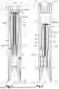
FIG. 1 shows a cross-sectional view of a tool configured to engage an object according to aspects of the disclosure, with an insert of the tool being depicted in a first position according to aspects of the disclosure;
FIG. 2 shows a cross-sectional view of the tool of FIG. 1, with the insert of the tool being depicted in a second position according to aspects of the disclosure;
FIG. 3 shows a partial enlarged view of the insert of the tool of FIG. 1 according to aspects of the disclosure;
FIG. 4 shows an exploded view of a tool string including the tool of FIG. 1 according to aspects of the disclosure;
FIG. 5 shows a schematic view of the tool of FIG. 1 according to aspects of the disclosure; and
FIG. 6 shows a schematic view of the tool of FIG. 1 according to aspects of the disclosure.
DETAILED DESCRIPTION
A tool configured to engage an object according to aspects of the disclosure is described with reference to FIGS. 1-6. Like numerals represent like parts, and the tool will generally be referred to by the reference numeral 10. Although the tool 10 is described with reference to specific examples, it should be understood that modifications and changes may be made to these examples without going beyond the general scope as defined by the claims. In particular, individual characteristics of the various examples shown and/or mentioned herein may be combined in additional examples. Consequently, the description and the drawings should be considered in a sense that is illustrative rather than restrictive. The Figures, which are not necessarily to scale, depict illustrative aspects and are not intended to limit the scope of the disclosure. The illustrative aspects depicted are intended only as exemplary.
The term “exemplary” is used in the sense of “example,” rather than “ideal.” While aspects of the disclosure are amenable to various modifications and alternative forms, specifics thereof have been shown by way of example in the drawings and will be described in detail. It should be understood, however, that the intention is not to limit aspects of the disclosure to a particular example described. On the contrary, the intention of this disclosure is to cover all modifications, equivalents, and alternatives falling within the scope of the disclosure.
Various materials, methods of construction, methods of fastening, and the like may be described in the context of disclosed examples. Those skilled in the art will recognize known substitutes for the materials, construction methods, fastening methods, and the like, all of which are contemplated as compatible with the disclosed example and are intended to be encompassed by the appended claims.
As used in this disclosure and the appended claims, the singular forms “a,” “an,” and “the” include plural referents, unless the content clearly dictates otherwise. As used in this disclosure and the appended claims, the term “or” is generally employed in a sense including “and/or,” unless the content clearly dictates otherwise.
Throughout the description, including the claims, the terms “comprising a,” “including a,” and “having a” should be understood as being synonymous with “comprising one or more,” “including one or more,” and “having one or more” unless otherwise stated. In addition, any range set forth in the description, including the claims, should be understood as including its end value(s), unless otherwise stated. Specific values for described elements should be understood to be within accepted manufacturing or industry tolerances known to one of skill in the art, and any use of the terms “substantially,” “approximately,” and “generally” should be understood to mean falling within such accepted tolerances.
When an element or feature is referred to herein as being “on,” “engaged to,” “connected to,” or “coupled to” another element or feature, it may be directly on, engaged, connected, or coupled to the other element or feature, or intervening elements or features may be present. In contrast, when an element or feature is referred to as being “directly on,” “directly engaged to,” “directly connected to,” or “directly coupled to” another element or feature, there may be no intervening elements or features present. Other words used to describe the relationship between elements or features should be interpreted in a like manner (e.g., “between” versus “directly between,” “adjacent” versus “directly adjacent,” etc.).
Spatially relative terms, such as “top,” “bottom,” “middle,” “inner,” “outer,” “beneath,” “below,” “lower,” “above,” “upper,” and the like may be used herein for ease of description to describe one element or relationship of a feature to another element(s) or feature(s) as illustrated in the drawings. Spatially relative terms may be intended to encompass different orientations of a device in use or operation in addition to the orientation depicted in the drawings. For example, if the device in the drawings is turned over, elements described as “below” or “beneath” other elements or features would then be oriented “above” the other elements or features. Thus, the example term “below” can encompass both an orientation of above and below. The device may be otherwise oriented (rotated 90 degrees or at other orientations) and the spatially relative descriptors used herein interpreted accordingly.
Although the terms “first,” “second,” “third,” etc. may be used herein to describe various elements, components, regions, layers, sections, and/or parameters, these elements, components, regions, layers, sections, and/or parameters should not be limited by these terms. These terms are only used to distinguish one element, component, region, layer, section, or parameter from another element, component, region, layer, section, or parameter. Thus, a first element, component, region, layer, section, or parameter discussed herein could be termed a second element, component, region, layer, section, or parameter without departing from the teachings of the present disclosure.
As shown by FIGS. 1-6, the tool 10 is configured to engage an object 100 (may also be referred to herein as a “fish 100”). In examples, the tool 10 may be configured to engage the object 100 in a subsurface operation. It is contemplated that the subsurface operation may correspond to excavation of a resource, such as oil and gas, water, and/or the like. Accordingly, the subsurface operation may include processes carried out in a wellbore of a subsurface field, such as an oil and gas field.
Referring to FIGS. 3-4 and 6, in examples, the object 100 may be referred to as and/or considered to be a support line, such as a wireline cable, a slickline cable, an electrical line cable, a braided line cable, a coiled tubing, and/or the like, configured to be used for conveyance of a tool string 200 within the wellbore during the subsurface operation. However, a support line will be referred to herein as “the object 100,” unless specific reference to a support line is otherwise necessary.
Referring to FIG. 4, a tool string 200 may extend between an upper end 210 and a lower end 212 and include one or more component and/or piece of equipment, such as a rope socket 220 configured to couple the tool string 200 to a support line; a stem 222 configured increase a weight of the tool string 200 and/or to sink the tool string 200; a jar 224 configured to generate impact on one or more of the tool string 200 and the wellbore; a knuckle joint 226 configured to provide flexibility to the tool string 200; a pulling and/or running tool 228 (may also be referred to herein as a “fishing tool 228” and/or an “overshot tool 228”) configured to retrieve equipment, such as the object 100, from the wellbore; and/or the like. The tool string 200 may be configured for operation, control, and/or analysis of the wellbore. It is contemplated that the terms “upper,” “upward,” “lower,” and “downward” may be understood in relation to the operator of the tool 10 when the tool 10 is positioned within the wellbore, such that an upper and upward position and/or direction is closer to the operator of the tool 10 than a lower and downward position and/or direction and a lower and downward position and/or direction is farther from the operator of the tool 10 than an upper and upward position and/or direction.
Additionally or alternatively, the object 100 may be referred to as and/or considered to be at least a portion of a tool string 200. In particular, the object 100 may be referred to as and/or considered to be a retrieval portion 230 (may also be referred to herein as a “fish neck 230”) of a tool string 200 to be retrieved from the wellbore (hereafter, referred to as a “non-operational tool string 200”), contoured and/or configured to be gripped to allow for a pulling action to be performed on the object 100 by an operator of the tool 10. It is contemplated that the non-operational tool string 200 may be understood as the tool string 200 that has become lost and/or lodged within the wellbore. In examples, the retrieval portion 230 of the non-operational tool string 200 may have a diameter that is less than one or more other diameter of the non-operational tool string 200. Additionally or alternatively, the retrieval portion 230 of the non-operational tool string 200 may be oriented at or adjacent to an upper end 210 of the non-operational tool string 200 when the non-operational tool string 200 is within the wellbore.
Referring to FIG. 4, in examples, it is contemplated that the tool 10 may be configured to be, referred to as, and/or considered to be included on a tool string 200 (hereafter, an “operational tool string 200”). It is contemplated that the operational tool string 200 may be understood as the tool string 200 in which the tool 10 may be coupled to for operation of the tool 10. The tool 10 may be coupled to the operational tool string 200 through a clamped connection, a threaded connection, and/or the like.
Referring to FIGS. 3-4 and 6, in examples, the tool 10 may be configured to engage the object 100 to retrieve the object 100 from the wellbore when the object 100 has become lost and/or lodged within the wellbore. Accordingly, it is contemplated that the tool 10 may be configured to function as, referred to as, and/or considered to be a “pulling and/or running tool 10” a “fishing tool 10” and/or an “overshot tool 10” configured to be coupled to the operational tool string 200. Additionally or alternatively, the tool 10 may be configured to engage the object 100 to couple the operational tool string 200 to the object 100 and/or support the operational tool string 200 within the wellbore. Accordingly, it is contemplated that the tool 10 may be configured to function as, referred to as, and/or considered to be a “rope socket 10” configured to be coupled to the operational tool string 200. However, the tool 10 will be described herein as being configured to engage the object 100 when the object 100 has become lost and/or lodged within the wellbore, unless reference to the tool 10 being configured to engage the object 100 to couple the operational tool string 200 to the object 100 and/or support the operational tool string 200 within the wellbore is otherwise necessary.
Referring to FIGS. 1-2 and 5-6, the tool 10 extends longitudinally between a first end 12 and a second end 14 along an axis A-A. In examples in which the tool 10 may be configured to engage the object 100 to retrieve the object 100 from the wellbore when the object 100 has become lost and/or lodged within the wellbore, it is contemplated that the first end 12 of the tool 10 may be referred to as and/or considered to be an upper end of the tool 10 and the second end 14 of the tool 10 may be referred to as and/or considered to be a lower end of the tool 10. In such examples, the tool 10 may be configured to be coupled to a lower end 212 of the operational tool string 200. In such examples, the first end 12 of the tool 10 may be configured to be coupled to the lower end 212 of the operational tool string 200. Additionally or alternatively, in examples in which the tool 10 may be configured to engage the object 100 to connect the operational tool string 200 to the object 100 and/or support the operational tool string 200 within the wellbore, it is contemplated that the first end 12 of the tool 10 may be referred to as and/or considered to be a lower end of the tool 10 and the second end 14 of the tool 10 may be referred to as and/or considered to be an upper end of the tool 10. In such examples, the tool 10 may be configured to be coupled to the upper end 210 of the operational tool string 200. In such examples, the second end 14 of the tool 10 may be configured to be coupled to the upper end 210 of the operational tool string 200.
As shown by FIGS. 1-3 and 5-6, the tool 10 includes an insert 20 configured to receive and/or engage the object 100. The insert 20 is configured to extend axially between the first end 12 and the second end 14 of the tool 10. Additionally, the insert 20 extends axially between a first end 22 and a second end 24 of the insert 20. The first end 22 of the insert 20 may be oriented at or adjacent to the first end 12 of the tool 10 and the second end 24 of the insert 20 may be oriented at or adjacent to the second end 14 of the tool 10. Additionally or alternatively, the first end 22 of the insert 20 may be oriented closer to the first end 12 of the tool 10 than the second end 24 of the insert 20 and the second end 24 of the insert 20 may be oriented closer to the second end 14 of the tool 10 than the first end 22 of the insert 20.
In examples, the insert 20 may be configured to receive and/or engage the object 100 circumferentially within a range of 10° and 360°. However, particularly, the insert 20 may be configured to receive and/or engage the object 100 circumferentially at 360°. Additionally or alternatively, the insert 20 may be configured to be substantially frustoconical in shape and, thus, may be configured to have a circumference. In particular, a second engagement surface 34 of the insert 20 (discussed in further detail below) may be configured to be substantially frustoconical in shape. In examples, the insert 20 may be formed in one integral part (not shown) configured to receive and/or engage the object 100 circumferentially. Alternatively, in examples, the insert 20 may include and/or be formed in a plurality of parts 20a, 20b configured to be oriented adjacently and/or circumferentially to receive and/or engage the object 100. In examples in which the insert 20 includes the plurality of parts 20a, 20b, the insert 20 may include at least a first part 20a and a second part 20b. The first part 20a and the second part 20b of the insert 20 may be configured to be separate from each other and substantially identical to each other in form and function. It is contemplated that the insert 20 including the first part 20a and the second part 20b of the insert 20 allows the insert 20 to be capable of receiving and/or engaging the object 100 when the object 100 has a non-uniform shape and/or a variable diameter.
In examples in which the insert 20 includes the plurality of parts 20a, 20b, the plurality of parts 20a, 20b may be configured to be evenly distributed and/or evenly spaced about the axis A-A. Additionally or alternatively, one or more of the insert 20 and a sleeve 40 (discussed in further detail below) of the tool 10 may include one or more alignment member 25a, 25b, 27a, 27b configured to maintain even distribution and/or even spacing between the plurality of parts 20a, 20b (i.e. the first part 20a and the second part 20b of the insert 20) about the axis A-A. In particular, one or more of the insert 20 and the sleeve 40 may include a first alignment member 25a, 25b included at or adjacent to the first end 22 of the insert 20 and a second alignment member 27a, 27b included at or adjacent to the second end 24 of the insert 20. Additionally or alternatively, one or more of the insert 20 and the sleeve 40 may include a primary first alignment member 25a configured to engage with a secondary first alignment member 25b at or adjacent to the first end 22 of the insert 20 and a primary second alignment member 27a configured to engage with a secondary second alignment member 27b at or adjacent to the second end 24 of the insert 20. In this manner, the insert 20 and/or the tool 10, is configured to prevent the object 100 from moving and/or becoming stuck between the plurality of parts 20a, 20b of the insert 20, thereby maintaining circumferential engagement of the object 100 and improving efficiency of the subsurface operation.
In examples in which the insert 20 includes the plurality of parts 20a, 20b, the insert 20 may further include one or more part beyond the first part 20a and the second part 20b of the insert 20. Particularly, the insert 20 may include between 3 parts (not shown) and 36 parts (not shown), inclusive of the first part 20a and the second part 20b of the insert 20. More particularly, the insert 20 may include between 3 parts and 8 parts (not shown), inclusive of the first part 20a and the second part 20b of the insert 20. However, the insert 20 will be described herein as including a configuration of the first part 20a and the second part 20b of the insert 20, unless reference to the insert 20 including a configuration of one integral part or the plurality of parts beyond the first part 20a and the second part 20b of the insert 20 is otherwise necessary. It should be understood that the structures and/or relationships described with respect to the configuration of the insert 20 being formed in the first part 20a and the second part 20b of the insert 20 may be correlated and/or applied to the configuration of the insert 20 being formed in one integral part or the plurality of parts beyond the first part 20a and the second part 20b of the insert 20. The first part 20a and the second part 20b may be referred to collectively herein as “the insert 20,” unless specific reference to the first part 20a and the second part 20b is otherwise necessary.
The insert 20 is configured to define one or more opening 26, 28 oriented about the axis A-A. In examples, the insert 20 is configured to define at least a first opening 26 at the first end 22 of the insert 20 and a second opening 28 defined at the second end 24 of the insert 20. The second opening 28 of the insert 20 is configured to receive the object 100. The insert 20 is configured to define a cavity 30 oriented about the axis A-A in communication with the first opening 26 and the second opening 28 of the insert 20. Additionally or alternatively, the cavity 30 extends substantially axially between the first opening 26 and the second opening 28 of the insert 20. In this manner, the insert 20 is configured to receive the object 100 through the second opening 28 defined at the second end 24 of the insert 20 and to receive the object 100 through the cavity 30 extending between the first opening 26 and the second opening 28 of the insert 20. Additionally, in this manner, the insert 20 is configured for radial movement and/or retraction toward and/or to the axis A-A.
As shown by FIGS. 1-2 and 5-6, the tool 10 includes a sleeve 40 configured to receive and/or engage the insert 20 and to receive the object 100. Accordingly, the insert 20 is configured to be received and/or engaged by the sleeve 40. It is contemplated that the sleeve 40 may be referred to as and/or considered to be a “housing 40.” The sleeve 40 is configured to extend axially between the first end 12 and the second end 14 of the tool 10. Additionally, the sleeve 40 extends axially between a first end 42 and a second end 44 of the sleeve 40. The first end 42 of the sleeve 40 may be oriented at or adjacent to the first end 12 of the tool 10 and the second end 44 of the sleeve 40 may be oriented at or adjacent to the second end 14 of the tool 10. Additionally or alternatively, the first end 42 of the sleeve 40 may be oriented closer to the first end 12 of the tool 10 than the second end 44 of the sleeve 40 and the second end 44 of the sleeve 40 may be oriented closer to the second end 14 of the tool 10 than the first end 42 of the sleeve 40. In examples, the sleeve 40 may be configured to be substantially frustoconical in shape and, thus, may be configured to have a circumference. In particular, a third engagement surface 54 (discussed in further detail below) of the sleeve 40 may be configured to be substantially frustoconical in shape.
The sleeve 40 defines one or more opening 46, 48 oriented about the axis A-A. In examples, the sleeve 40 defines at least a first opening 46 at the first end 42 of the sleeve 40 and a second opening 48 at the second end 44 of the sleeve 40. The second opening 48 of the sleeve 40 is configured to receive the object 100. Additionally, the sleeve 30 may be configured to find and/or guide the object 100 into the second opening 48 of the sleeve 40. Accordingly, the sleeve 40 may include a skirt 56 configured to come in contact with one or more of the object 100 and the wellbore to find and/or guide the object 100 into the second opening 48 of the sleeve 40 (see FIG. 6). In examples, the skirt 56 may be elastically deformable. Additionally, the second opening 48 of the sleeve 40 may be configured to guide the object 100 into the insert 20. Accordingly, the second opening 48 of the sleeve 40 may be substantially frustoconical in shape, such that a diameter of the second opening 48 of the sleeve 40 is decreased toward the insert 20 (see FIGS. 1-2 and 6).
The sleeve 40 defines a chamber 50 oriented about the axis A-A in communication with the first opening 46 and the second opening 48 of the sleeve 40. Additionally or alternatively, the chamber 50 extends substantially axially between the first opening 46 and the second opening 48 of the sleeve 40. The chamber 48 is configured to receive the insert 20 between the first end 42 and the second end 44 of the sleeve 40. In examples, the first end 42 of the sleeve 40 may be closed to maintain the insert 20 within the chamber 50. Additionally or alternatively, referring to FIG. 5, the first end 42 of the sleeve 40 may be open and include a cover 52 configured to maintain the insert 20 within the chamber 50.
The first end 22 of the insert 20 may be oriented at or adjacent to the first end 42 of the sleeve 40 and/or the first end 12 of the tool 10 and the second end 24 of the insert 20 may be oriented at or adjacent to the second end 44 of the sleeve 40 and/or the second end 14 of the tool 10. Additionally or alternatively, the first end 22 of the insert 20 may be oriented closer to the first end 42 of the sleeve 40 and/or the first end 12 of the tool 10 than the second end 24 of the insert 20 and the second end 24 of the insert 20 may be oriented closer to the second end 44 of the sleeve 40 and/or the second end 14 of the tool 10 than the first end 22 of the insert 20. The second opening 28 of the insert 20 may substantially aligned with the second opening 48 of the sleeve 40 about the axis A-A. In this manner, the sleeve 40 is configured to receive and/or engage the insert 20 within the chamber 50 and to receive the object 100 through the second opening 48 defined at the second end 44 of the sleeve 40, such that the insert 20 is capable of receiving the object 100 through the second opening 28 defined at the second end 24 of the insert 20 and engaging the object 100 within the cavity 30 of the insert 20 when the object 100 is received through the second opening 48 defined at the second end 44 of the sleeve 40.
The insert 20 includes a first engagement surface 32 configured to be engaged by the sleeve 40 and a second engagement surface 34 configured to receive and/or engage the object 100. It is contemplated that the first engagement surface 32 of the insert 20 may be referred to as and/or considered to be a “wall 32” and/or a “first wall 32” of the insert 20 and/or the tool 10 and the second engagement surface 34 of the insert 20 may be referred to as and/or considered to be a “wall 34” and/or a “second wall 34” of the insert 20 and/or the tool 10. In examples, the first engagement surface 32 of the insert 20 is oriented outward of the second engagement surface 34 of the insert 20. Accordingly, it is contemplated that the first engagement surface 32 of the insert 20 may be referred to as and/or considered to be an “outer engagement surface 32” of the insert 20 and the second engagement surface 34 of the insert 20 may be referred to as and/or considered to be an “inner engagement surface 34” of the insert 20. Additionally, it is contemplated that the terms “outer,” “outward,” “inner,” and “inward” may be understood in relation to the axis A-A, such that the terms “outer” and “outward” correspond to a position and/or direction that is further in relation to the axis A-A than an “inner” and “inward” position and/or direction and the terms “inner” and “inward” correspond to a position and/or direction that is closer in relation to the axis A-A than an “outer” and “outward” position and/or direction.
Referring to FIG. 5, the first engagement surface 32 of the insert 20 is configured to receive a first force F1 exerted on the insert 20 by the sleeve 40. In examples, the first force F1 may be received and/or exerted substantially perpendicular to the axis A-A. Accordingly, it is contemplated that the first force F1 may be referred to as and/or considered to be a “radial force.” The second engagement surface 34 of the insert 20 is configured to exert a second force F2 on the object 100. In particular, the second engagement surface 34 of the insert 20 may be configured to exert the second force F2 on the object 100 when the first force F1 is exerted on the first engagement surface 32 of the insert 20 by the sleeve 40. In examples, the second force F2 exerted on the object 100 by the second engagement surface 34 of the insert 20 may be referred to as and/or considered to be a transfer of the first force F1 and/or the same as the first force F1 exerted on the first engagement surface 32 of the insert 20 by the sleeve 40.
The second engagement surface 34 of the insert 20 is configured to be in surface-to-surface engagement with the object 100. In examples, the second force F2 may be exerted substantially perpendicular to the axis A-A. Accordingly, it is contemplated that the second force F2 may be referred to as and/or considered to be a “radial force.” In examples, the second engagement surface 34 of the insert 20 is configured to define the first opening 26 and the second opening 28 of the insert 20. Additionally, the second engagement surface 34 of the insert 20 is configured to define the cavity 30 of the insert 20. In examples, the second engagement surface 34 of the insert 20 may be included substantially parallel to the axis A-A. Additionally or alternatively, the second engagement surface 34 of the insert 20 may be included substantially parallel to a force (i.e. a third force F3, discussed in further detail below) exerted on the second engagement surface 34 of the insert 20 by the object 100. In this manner, the second engagement surface 34 of the insert 20 is configured to exert the second force F2 on the object 100 when the object 100 is received through the second opening 28 and the cavity 30 defined by the insert 20 and the first force F1 is exerted on the first engagement surface 32 of the insert 20 by the sleeve 40. Additionally, in this manner, the second engagement surface 34 of the insert 20 is configured to engage the object 100 substantially longitudinally and/or without bending the object 100, thereby preventing damage to the object 100.
Referring to FIGS. 1-3 and 5, the second engagement surface 34 of the insert 20 may include one or more projection 36a, 36b configured to increase friction and/or traction between the second engagement surface 34 of the insert 20 and the object 100 when the object 100 is received by the insert 20. Additionally or alternatively, the projection 36a, 36b may be configured to grip and/or penetrate one or more layer (not shown) included by the object 100. It is contemplated that the projection may be configured as, considered to be, and/or referred to as a “tooth 36a, 36b,” “teeth 36a, 36b,” a “thread 36a, 36b,” and/or “threads 36a, 36b.” In examples, the second engagement surface 34 of the insert 20 may include a plurality of the projection 36a, 36b arranged along the second engagement surface 34 of the insert 20 between the first end 22 and the second end 24 of the insert 20. Additionally or alternatively, the second engagement surface 34 of the insert 20 may include one or more of a plurality of a first projection 36a and a plurality of a second projection 36b arranged along the second engagement surface 34 of the insert 20 between the first end 22 and the second end 24 of the insert 20.
In examples, each first projection 36a of the plurality of the first projections 36b extends to a first length. Each first projection 36a of the plurality of first projections 36a may be configured to grip and/or penetrate a first layer (may also be referred to as an “outer layer”) (not shown) of the object 100. It is contemplated that the first layer of the object 100 may be constructed of a polymer and/or the like configured to form a protective barrier layer of the object 100 (i.e. of a composite cable). In examples, each second projection 36b of the plurality of second projections may extend to a second length greater than the first length of each first projection 36a of the plurality of first projections 36a. Each second projection 36b of the plurality of second projections 36b may be configured to grip and/or penetrate a second layer (may also be referred to as an “inner layer”) (not shown) of the object 100. It is contemplated that the first layer of the object 100 may be constructed of metallic fibers and/or the like configured to form an armor barrier layer of the object 100 (i.e. of a composite cable). In this manner, the second engagement surface 34 of the insert 20 may be configured to secure the engagement between the second engagement surface 34 of the insert 20 and the object 100, such that the object 100 is prevented from slipping out of engagement with the second engagement surface 34 of the insert 20.
As shown by FIGS. 1-2 and 5-6, the sleeve 40 includes a third engagement surface 54 configured to engage the first engagement surface 32 of the insert 20. It is contemplated that the third engagement surface 54 of the sleeve 40 may be referred to as and/or considered to be a “wall 54” and/or a “third wall 54” of the sleeve 40 and/or the tool 10. In particular, the third engagement surface 54 of the sleeve 40 is configured to exert the first force F1 on the first engagement surface 32 of the insert 20. Accordingly, the third engagement surface 54 of the sleeve 40 and the first engagement surface 32 of the insert 20 are configured to be in surface-to-surface engagement with each other. In examples, the third engagement surface 54 of the sleeve 40 defines the second opening 48 of the sleeve 40. Additionally, the third engagement surface 54 of the sleeve 40 defines the chamber 50 of the sleeve 40. In examples in which the first end 42 of the sleeve 40 is open, the third engagement surface 54 of the sleeve 40 may define the first opening 46 of the sleeve 40. Accordingly, it is contemplated that the third engagement surface 54 of the sleeve 40 may be referred to as and/or considered to be an “inner engagement surface 54” of the sleeve 40. In this manner, the third engagement surface 54 of the sleeve 40 is configured to exert the first force F1 on the first engagement surface 32 of the insert 20 when the object 100 is received through the second opening 48 and the cavity 30 defined by the insert 20.
Referring to FIGS. 5-6, the second engagement surface 34 of the insert 20 is configured to receive a third force F3 exerted on the second engagement surface 34 of the insert 20 by the object 100 when the object 100 is received within the cavity 30 of the insert 20. It is contemplated that the third force F3 exerted on the second engagement surface 34 of the insert 20 by the object 100 corresponds to a weight and/or gravitational force of the object 100. Additionally, it is contemplated that the third force F3 exerted on the second engagement surface 34 of the insert 20 by the object 100 may be exerted in response to an upward pulling action performed on the tool 10 and/or the object 100 by the operator of the tool 10. In examples, the third force F3 may be received and/or exerted substantially parallel to the axis A-A. Accordingly, it is contemplated that the third force F3 may be referred to as and/or considered to be an “axial force.” Additionally, it is contemplated that the third force F3 is exerted on the second engagement surface 34 of the insert 20 by the object 100 in a direction toward and/or to the second end 44 of the sleeve 40 and/or the second end 14 of the tool 10.
As illustrated by FIGS. 1-2, the insert 20 is configured to be moved axially between at least a first position (see FIG. 1) and a second position (see FIG. 2) within the chamber 50 of the sleeve 40 when the object 100 is received within the cavity 30 of the insert 20. In examples, the first position of the insert 20 may correspond to an orientation of the insert 20 within the chamber 50 of the sleeve 40 that is closer to the first end 42 of the sleeve 40 and/or the first end 12 of the tool 10 than an orientation of the insert 20 when the insert 20 is in the second position. The second position of the insert 20 may correspond to an orientation of the insert 20 within the chamber 50 of the sleeve 40 that is closer to the second end 44 of the sleeve 40 and/or the second end 14 of the tool 10 than an orientation of the insert 20 when the insert 20 is in the first position.
In examples, the insert 20 is configured to be moved axially from the first position toward and/or to the second position when the third force F3 is exerted on the second engagement surface 34 of the insert 20 by the object 100. The first engagement surface 32 of the insert 20 is configured to slide against the third engagement surface 54 of the sleeve 40 when the insert 20 is moved between the first position and the second position. Referring to FIG. 6, in examples, the tool 10 may include a bias member 60, such as a compression spring and/or the like, oriented between the first end 22 of the insert 20 and the first end 42 of the sleeve 40 and/or the first end 12 of the tool 10. The bias member 60 may be configured to bias the insert 20 toward and/or to the second position to maintain engagement of the object 100 by the second engagement surface 34 of the insert 20. Additionally or alternatively, in examples, the insert 20 may be configured to be moved axially from the second position toward and/or to the first position when the object 100 is received through the second opening 48 of the sleeve 40 and the object 100 pushes against the second end 24 of the insert 20. Movement of the insert 20 from the second position toward the first position may move and/or expand the second engagement surface 34 of the insert radially outwardly, such that a diameter of the second opening 28 and the cavity 30 of the insert 20 is increased until the object 100 may be received, thereby allowing the object 100 to be received within the second opening 28 and the cavity 30 of the insert 20. In this manner, the object 100 may be received by the insert 20, regardless of a dimension and contour of the object 100.
The third engagement surface 54 of the sleeve 40 is configured to initiate and/or increase the first force F1 exerted on the first engagement surface 32 of the insert 20 when the insert 20 is moved from the first position toward and/or to the second position. Additionally, the second engagement surface 34 of the insert 20 is configured to initiate and/or increase the second force F2 exerted on the object 100 when the insert 20 is moved from the first position toward and/or to the second position. In examples, the initiation and/or increase of the first force F1 exerted on the first engagement surface 32 of the insert 20 may move and/or retract the second engagement surface 34 of the insert 20 radially inwardly, such that a diameter of the cavity 30 of the insert 20 is decreased, thereby initiating and/or increasing the second force F2 exerted on the object 100 by the second engagement surface 34 of the insert 20. In this manner, the insert 20 is moved axially from the first position toward and/or to the second position when the third force F3 is exerted on the second engagement surface 34 of the insert 20 and the second force F2 exerted on the object 100 by the second engagement surface 34 of the insert 20 is increased when the insert 20 is moved from the first position toward and/or to the second position, such that the second engagement surface 34 of the insert 20 is capable of engaging the object 100 automatically when the third force F3 is exerted on the second engagement surface 34 of the insert 20 by the object 100.
Referring to FIG. 5, the third engagement surface 54 of the sleeve 40 is configured to decrease a diameter of the chamber 50 of the sleeve 40 from the first end 42 of the sleeve 40 toward and/or to the second end 44 of the sleeve 40. Accordingly, the third engagement surface 54 of the sleeve 40 is included at a first angle α relative to the axis A-A. In examples, the first angle α of the third engagement surface 54 of the sleeve 40 may be included within a range between 0.1° and 40°. Particularly, the first angle α may be included within a range between 1° and 10°. More particularly, the first angle α may be included within a range between 1° and 5°. In this manner, the third engagement surface 54 of the sleeve 40 is configured to increase the first force F1 exerted on the first engagement surface 32 of the insert 20 as a result of the insert 20 being moved from the first position toward and/or to the second position.
Referring to FIG. 5, the first engagement surface 32 of the insert 20 is configured to decrease a diameter of the insert 20 from the first end 22 of the insert 20 toward and/or to the second end 24 of the insert 20. Accordingly, the first engagement surface 32 of the insert 20 is included at a second angle β relative to the axis A-A. The second angle β of the first engagement surface 32 of the insert 20 may be substantially identical to the first angle α of the third engagement surface 54 of the sleeve 40. In examples, the second angle β of the first engagement surface 32 of the insert 20 may be included within a range between 0.1° and 40°. Particularly, the second angle β may be included within a range between 1° and 10°. More particularly, the second angle β may be included within a range between 1° and 5°. In this manner, the first engagement surface 32 of the insert 20 is configured to cooperate with the third engagement surface 54 of the sleeve 40 to guide movement of the insert 20 from the first position toward and/or to the second position, as the diameter of the chamber 50 of the sleeve 40 is decreased by the third engagement surface 54 of the sleeve 40 from the first end 42 of the sleeve 40 toward and/or to the second end 44 of the sleeve 40. Additionally, in this manner, the first engagement surface 32 of the insert 20 is configured to cooperate with the third engagement surface 54 of the sleeve 40 to initiate and/or increase the first force F1 exerted on the first engagement surface 32 of the insert 20 and, thus, the second force F2 exerted by the second engagement surface 34 of the insert 20 on the object 100, as the diameter of the chamber 50 is decreased by the third engagement surface 54 of the sleeve 40 from the first end 42 of the sleeve 40 toward and/or to the first end 42 of the sleeve 40.
In operation, once the insert 20 has been moved from the first position toward and/or to the second position, thereby increasing the second force F2 exerted by the second engagement surface 34 of the insert 20 on the object 100, the object 100 becomes securely engaged within the cavity 30 of the insert. Once the object 100 is securely engaged within the cavity 30, the operator may initiate and/or continue the upward pulling action performed on the tool 10 and/or the object 100 to retrieve the object 100 from the wellbore. Additionally or alternatively, once the object 100 is securely engaged within the cavity 30, the operator may initiate and/or continue the upward pulling action to couple the object 100 to the operational tool string 200 and/or support the operational tool string 200 within the wellbore.
Depending on the object 100, it is contemplated that one or more of the first angle α of the third engagement surface 54 of the sleeve 40 and the second angle β of the first engagement surface 32 of the insert 20 may be configured to be adjusted and/or calibrated. In examples, the adjustment and/or calibration of one or more of the first angle α of the third engagement surface 54 of the sleeve 40 and the second angle of the first engagement surface 32 of the insert 20 may be determined in view of a ratio and/or equation corresponding to one or more of the first force F1 exerted by the third engagement surface 54 of the sleeve 40 on the first engagement surface 32 of the insert 20, the second force F2 exerted by the second engagement surface 34 on the object 100, and the third force F3 exerted by the object 100 on the second engagement surface 34 of the insert 20. In examples, the ratio and/or equation that may be used to determine one or more of the first angle α of the third engagement surface 54 of the sleeve 40 and the second angle β of the first engagement surface 32 of the insert 20 may be:
F 3 = F 1 or F 2 2 tan ( α or β )
In this manner, the tool 10 is configured to automatically and securely engage the object 100 in the subsurface operation, dynamically and adaptively to grip objects 100 of various dimensions and contours, in a manner in which the object 100 is retrieved and/or supported substantially longitudinally and without bending.
Although the present disclosure herein has been described with reference to particular examples, it is to be understood that these examples are merely illustrative of the principles and applications of the present disclosure.
It is intended that the specification and examples be considered as exemplary only, with a true scope of the disclosure being indicated by the following claims.
Additionally, all of the disclosed features of an apparatus may be transposed, alone or in combination, to a method and vice versa.
Claims
What is claimed is:1. A tool configured to engage an object corresponding to a subsurface operation, the tool extending longitudinally between a first end and a second end along an axis, the tool comprising:
an insert configured to be moved axially between at least a first position and a second position, the insert including a first engagement surface configured for movement of the insert between the first position and the second position and a second engagement surface configured to receive an object; and
a sleeve configured to receive the insert, the sleeve including a third engagement surface configured to cooperate with the first engagement surface of the insert for movement of the insert between the first position and the second position;
wherein the second engagement surface of the insert is configured to be moved radially inwardly when the insert is moved from the first position toward the second position.
2. The tool according to claim 1, wherein the first engagement surface of the insert is configured to receive a first force exerted on the first engagement surface of the insert and the second engagement surface of the insert is configured to exert a second force on the object when the first force is exerted on the first engagement surface of the insert.
3. The tool according to claim 2, wherein the third engagement surface of the sleeve is configured to exert the first force on the first engagement surface of the insert when the object is received by the insert.
4. The tool according to claim 1, wherein the second engagement surface of the insert is configured to receive a third force exerted on the second engagement surface of the insert by the object when the object is received by the insert.
5. The tool according to claim 4, wherein the insert is configured to be moved from the first position toward the second position when the third force is exerted on the second engagement surface of the insert by the object.
6. The tool according to claim 3, wherein the third engagement surface of the sleeve is configured to increase the first force exerted on the first engagement surface of the insert when the insert is moved from the first position toward the second position.
7. The tool according to claim 2, wherein the second engagement surface of the insert is configured to increase the second force exerted on the object when the insert is moved from the first position toward the second position.
8. The tool according to claim 1, wherein the third engagement surface of the sleeve is included at a first angle relative to the axis and the first angle of the third engagement surface of the sleeve is included within a range between 0.1° and 40°.
9. The tool according to claim 1, wherein the first engagement surface of the insert is included at a second angle relative to the axis and the second angle of the first engagement surface of the insert is included within a range between 0.1° and 40°.
10. The tool according to claim 1, wherein the insert is formed in at least a first part and a second part and the first part and the second part of the insert are evenly distributed about the axis.
11. The tool according to claim 1, wherein the insert defines an opening in communication with a cavity and the opening of the insert is configured to receive the object.
12. The tool according to claim 1, wherein the sleeve defines an opening in communication with a chamber and the opening of the sleeve is configured to receive the object.
13. The tool according to claim 1, wherein the second engagement surface of the insert includes a plurality of projections configured to increase friction between the second engagement surface of the insert and the object when the object is received by the insert.
14. The tool according to claim 1, comprising a bias member oriented between the insert and the first end of the tool.
15. A method of engaging an object corresponding to a subsurface operation, the method comprising:
providing the tool according to claim 1; and
receiving an object within the insert.
Images & Drawings included:


Sources:
- United States Patent and Trademark Office - verify current appl. status at the USPTO↗
Recent applications in this class:
- » 20250314144 2025-10-09
Downhole Fish Grabbing Tool - » 20240410245 2024-12-12
DOWNHOLE CAMERA ENHANCED MANIPULATION TOOL - » 20240328272 2024-10-03
ROTATING OVERSHOT GUIDE - » 20240287862 2024-08-29
HARDENED GRAPPLING ELEMENTS FOR RETRIEVING DOWNHOLE TOOLS - » 20240209708 2024-06-27
WASHOVER TOOLS, SYSTEMS, AND METHODS OF USE - » 20240068316 2024-02-29
Tubular cutting and fishing tool - » 20230399912 2023-12-14
OVERSHOT ASSEMBLY - » 20230272686 2023-08-31
Inverted tapered overshot - » 20230193715 2023-06-22
VISUALIZATION OF FISH WHILE FISHING IN A WELLBORE - » 20230184046 2023-06-15
Robotic fishing tool