Energized Connectivity Completions Technology
US20260176941A1
2026-06-25
17/985,073
2022-11-10
Smart Summary: Energized Connectivity Completions Technology offers a new way to extract oil and gas without fracking. It uses energy and electricity to create pathways in the ground, allowing oil and gas to flow to the surface. This method is safer for the environment because it avoids harmful chemicals and reduces the risk of earthquakes. It also helps lower carbon emissions, making it better for the planet. Overall, this technology aims to improve oil and gas production while protecting natural resources. 🚀 TL;DR
Abstract:
The completions process eliminates the Oil & Gas Industry's need for fracking and improves the production process. This process uses energy and electricity, instead of chemicals and hydraulic fracturing to create pathways (fractures) which enable the formation to deliver petroleum fluids to the surface. This process reduces our carbon footprint and eliminates the chemical dangers to the water table and threat of earthquakes.
Applicant:
Interested in similar patents?
Get notified when new applications in this technology area are published.
Classification:
E21B43/2401 » CPC main
Methods or apparatus for obtaining oil, gas, water, soluble or meltable materials or a slurry of minerals from wells; Enhanced recovery methods for obtaining hydrocarbons using heat, e.g. steam injection by means of electricity
E21B43/2405 » CPC further
Methods or apparatus for obtaining oil, gas, water, soluble or meltable materials or a slurry of minerals from wells; Enhanced recovery methods for obtaining hydrocarbons using heat, e.g. steam injection in association with fracturing or crevice forming processes
E21B17/003 » CPC further
Drilling rods or pipes; Flexible drill strings; Kellies; Drill collars; Sucker rods; Casings Cables; ; Tubings with electrically conducting or insulating means
E21B33/12 » CPC further
Sealing or packing boreholes or wells in the borehole Packers; Plugs
E21B43/24 IPC
Methods or apparatus for obtaining oil, gas, water, soluble or meltable materials or a slurry of minerals from wells; Enhanced recovery methods for obtaining hydrocarbons using heat, e.g. steam injection
E21B17/00 IPC
Drilling rods or pipes; Flexible drill strings; Kellies; Drill collars; Sucker rods; Casings Cables; ; Tubings
Description
CROSS-REFERENCE TO RELATED APPLICATIONS
No cross reference applies.
STATEMENT REGARDING FEDERALLY SPONSORED RESEARCH OR DEVELOPMENT (IF APPLICABLE)
Federally sponsored research does not apply.
REFERENCE TO SEQUENCE LISTING, A TABLE, OR A COMPUTER PROGRAM LISTING COMPACT DISC APPENDIX (IF APPLICABLE)
No sequence listing applies.
BACKGROUND OF THE INVENTION
Through multiple applications, testing, research, and verification, it is found that this Process Utility Patent is specific, non-related to current technology, unique, and proven. The history of the creation of this process patent began with the small scale application for art and design purposes through the Lichtenberg wood burning application. Through further testing it was found to have the appropriate effect for application with a sedimentary and/or conglomerate rock media for the purpose of industry application.
BRIEF SUMMARY OF THE INVENTION
The completions process, or fracturing method, is intended to establish, improve, and increase connectivity between parallel wellbores. This increases permeability improves transport of in-situ fluids within the formation for means of delivery to wellbore and then surface. This process applies High Voltage electricity through means of AC, DC, or transformer regulated current from one wellbore to the parallel wellbore in order to create a network of fulgurite pathways for fluid transport.
BRIEF DESCRIPTION OF THE SEVERAL VIEWS OF THE DRAWINGS
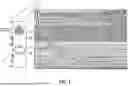
FIG. 1 is a schematic view of an oil and gas formation with multiple wellbores disposed therein and a power supply.
FIG. 2 is a schematic view of the oil and gas formation with multiple wellbores disposed therein and depicting the power being supplied to the formation.
FIG. 3 shows a close-up view of a part of FIG. 2 showing the power being supplied to the formation.
FIG. 4 is a schematic view of the oil and gas formation with multiple wellbores disposed therein and the power supply showing the fractures depicted in the formation.
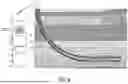
FIG. 5 is a close-up view of FIG. 4 showing the fractures generated in the formation.
FIG. 6 is a schematic view of the oil and gas formation with multiple wellbores disposed therein and the power supply after flow is established in the wellbores.
FIG. 7 is a diagrammatic view of conductive apparatus disposed in the wellbores and associated oil and gas components.
DETAILED DESCRIPTION OF THE INVENTION
The completions process utilizes electricity to initiate and establish the connectivity from the completions application of an oil or gas well. As shown in FIG. 1, parallel wells 10a and 10b have been drilled (open not cased) into an oil and gas formation 12 within 2000′ of each other and have been made static, the process is ready setup.
A High Voltage transformer 14 and/or energy source is prepared on location for the purpose of delivering High Voltage electricity from one pole located in one wellbore 10a at specific measured depth, to the adjacent pole in the parallel wellbore 10b at the corresponding and relative measured depth. High Voltage Cable 16a or 16b, such as XLPE, PEF, PTFE, or FEP, is connected to each of the transmitting and receiving poles. Each cable 16a and 16b is then tethered and connected to a conductive device 18a and 18b pictured in FIG. 7. The cable and conductive device is attached in-line with a well tractor 20a and 20b, which is spaced 30′ behind the conductive device 18a and 18b, for the purpose of delivery down hole. Twelve feet behind the tractor 20a or 20b, a pump down pressure activated rubberized plug 22a and 22b can also be attached.
Once the conductive devices 18a and 18b are at their respective specified depths, a pump down unit (not shown) pressures up the rubberized plugs 22a and 22b, sealing the wellbores 10a and 10b in front of the plugs 22a and 22b, isolating the devices 18a and 18b. Once isolation is verified in both wellbores 10a and 10b and depth has been re-verified, the energized process may begin. FIGS. 2 and 3 depict the energized process occurring between the wellbores 10a and 10b in the formation 12.
The energy source is turned on and voltmeters are brought online for observation. The energy source is powered up and electricity is delivered downhole to begin the process. Once the electricity reaches the conductive devices 18a and 18b, connectivity begins to occur in a branch like pattern surround the wellbores 10a and 10b in a radial geometry with a tendency for reaching the opposite pole. Both electrical sources downhole are delivering high voltage through the formation 12 and conductivity is established by the in-situ connate saltwater within the formation 12. The voltage for the process can be greater than about 20 Kva in one embodiment. In another embodiment, the voltage can be greater than about 50 Kva. Once the electricity reaches each pore space, a Fulgurite formation of the sandstone or limestone will be created. The fulgurite formation establishes the connectivity and the throat space for fluid delivery from the formation 12, to the wellbores 10a and 10b, and finally to the surface. FIGS. 4 and 5 show the resulting fractures 24 in the formation 12, and FIG. 6 shows the production fluids 26 in the wellbores 10a and 10b being transported to the surface.
The process is finalized when the poles deliver successfully electricity to each other and the voltmeter verifies that connection has been made. The plugs 22a and 22b can be released, the tools are retrieved, and the process is repeated for each predetermined stage (measured depth) of the wellbores 10a and 10b for the purpose of fully executing the process of an entire wellbore completion.
Claims
What is claimed is:1. A method of creating fractures in an oil and gas formation, the method comprising:
electrifying an oil and gas formation between a first wellbore and a second wellbore to generate fractures in the oil and gas formation.
2. The method of claim 1 further comprising running a first high voltage cable into the first wellbore and a second high voltage cable into the second wellbore.
3. The method of claim 2 further comprising a first conductive device extended down into the first wellbore and electrically connected to the first high voltage cable and a second conductive device extended down into the second wellbore and electrically connected to the second high voltage cable.
4. The method of claim 3 further comprising setting plugs in the first and second wellbores at a first location to isolate a first zone in the formation to be fractured.
5. The method of claim 4 further comprising well tractors to deliver the first and second high voltage cables to a location in the first and second wellbores.
6. The method of claim 2 wherein the oil and gas formation is electrified by directing current to the first and second high voltage cables.
7. The method of claim 6 wherein the current is provided to the first and second high voltage cables via a transformer.
8. The method of claim 2 wherein the first high voltage cable is an energized pole and the second high voltage cable is a receiving pole.
9. The method of claim 4 further comprising unsetting the plugs to permit production fluids to flow in the first and second wellbores.
10. The method of claim 9 further comprising capturing the production fluids flowing into the first or second wellbore.
11. The method of claim 4 further comprising:
moving the plugs and the first and second conductive devices to a second location in the first and second wellbores;
setting the plugs in the second location to isolate a second zone in the formation to be fractured; and
electrifying the formation to create fractures in the formation at the second location.
12. The method of claim 11 further comprising unsetting the plugs to allow production fluids from the second location to flow into the first and second wellbores and be recovered.
Images & Drawings included:


Sources:
- United States Patent and Trademark Office - verify current appl. status at the USPTO↗
Recent applications in this class:
- » 20250314163 2025-10-09
FLUID INJECTION FOR DEHYDROGENATION - » 20250283396 2025-09-11
RE-START OF WELL AFTER A WELL KILL OPERATION - » 20240392667 2024-11-28
Method and system for oil recovery using solvent-assisted electric heating - » 20240328292 2024-10-03
EXTRACTION FROM A FORMATION WITH INDUCTION HEATING - » 20240280008 2024-08-22
GASEOUS HYDROCARBON FORMATION HEATING DEVICE - » 20240271512 2024-08-15
DOWNHOLE ELECTRIC STEAM GENERATOR WITH HEATING ELEMENTS - » 20240240547 2024-07-18
SYSTEMS AND METHODS FOR CONTROLLING ELECTROMAGNETIC ENERGY DELIVERY TO A LOAD - » 20240209718 2024-06-27
SIGNAL GENERATORS FOR ELECTROMAGNETIC HEATING AND SYSTEMS AND METHODS OF PROVIDING THEREOF - » 20240117723 2024-04-11
MOBILIZING HEAVY OIL - » 20240052737 2024-02-15
Treatment of organic deposits using microwave heating