SYSTEMS AND METHODS FOR IDENTIFICATION, REPORTING, AND CORRECTION OF WELL THICKNESS DATA USING A MACHINE LEARNING CLUSTERING ALGORITHM
US20260176957A1
2026-06-25
19/409,966
2025-12-05
Smart Summary: A method has been developed to improve the accuracy of well thickness data. It starts by gathering different types of thickness measurements from a well, including raw data and information from a completion file. These measurements are grouped into clusters based on depth ranges to analyze them better. After clustering, corrected thickness values are calculated from these groups and compared to identify any errors. Finally, the method helps to pinpoint and correct discrepancies in the thickness measurements for better reliability. 🚀 TL;DR
Abstract:
A method includes receiving raw measurements of a well, receiving thickness measurements from a well completion file of the well, receiving computed thickness measurements of the well, clustering the raw measurements into a first plurality of clusters, wherein each cluster of the first plurality of clusters corresponds to a particular range of depths, obtaining a corrected phase thickness using the first plurality of clusters, the signals, and the computed thickness measurements, clustering the thickness measurements from the well completion file into a second plurality of clusters, obtaining a corrected well thickness using the second plurality of clusters, the well completion file, and the computed thickness measurements, and identifying corrections in the computed thicknesses from corrected raw measurement thickness and corrected well completion thickness based on differences between each of the corrected raw measurement thickness, the corrected well completion thickness, and the computed thickness measurements.
Applicant:
Interested in similar patents?
Get notified when new applications in this technology area are published.
Classification:
E21B47/006 » CPC main
Survey of boreholes or wells Detection of corrosion or deposition of substances
E21B47/04 » CPC further
Survey of boreholes or wells Measuring depth or liquid level
E21B47/00 IPC
Survey of boreholes or wells
Description
BACKGROUND
The present disclosure relates generally to systems and methods for identification, reporting, and correction of well thickness data using a depth constraining, convergent machine learning clustering algorithm.
This section is intended to introduce the reader to various aspects of art that may be related to various aspects of the present disclosure, which are described and/or claimed below. This discussion is believed to be helpful in providing the reader with background information to facilitate a better understanding of the various aspects of the present disclosure. Accordingly, it may be understood that these statements are to be read in this light, and not as admissions of prior art.
A well site may include a drilling rig configured to drill a borehole into a subterranean formation and to position downhole well tools and equipment within the borehole to facilitate completion and hydrocarbon production operations of the well. Well integrity evaluations, such as well casing (e.g., pipes, tubes, etc.) integrity evaluations, provide information relevant to natural resource production (e.g., oil, gas, water, hydrocarbon, etc.). A high integrity well casing may include a well casing in such a condition that unintended fluid movement or loss of containment to the environment in drilling and well operations is avoided. A low integrity well casing may include well casing defects that may cause strength degradation, casing deformation, well suspension, well abandonment, and the like. Complexity inside and surrounding the well in different environments may create challenges for accurately mapping various casing defects, such as well thickness variations due to wear or corrosion. For example, computed thickness of a well may differ from true thickness due to human error (e.g., incorrectly calculating a transformation factor), measurement limitations (e.g., inability to differentiate chrome (e.g., chromium, alloy) pipe, poor sensitivity to outer pipes, etc.), and inability to differentiate pipe joints.
SUMMARY
A summary of certain embodiments disclosed herein is set forth below. It should be understood that these aspects are presented merely to provide the reader with a brief summary of these certain embodiments and that these aspects are not intended to limit the scope of this disclosure. Indeed, this disclosure may encompass a variety of aspects that may not be set forth below.
In certain embodiments, a method includes receiving signals indicative of electromagnetic interactions with a well casing of a well, wherein the signals includes raw measurements across a first set of depths of the well, receiving a well completion file associated with the well, wherein the well completion file includes thickness values across a second set of depths of the well, receiving computed thickness measurements across a third set of depths of the well, clustering the raw measurements from the signals into a first plurality of clusters, wherein each cluster of the first plurality of clusters corresponds to a particular range of depths, merging a first cluster and a second cluster of the first plurality of clusters to generate a first plurality of merged clusters, wherein the first cluster and the second cluster are merged based on the first cluster being within one pipe joint of the second cluster and the first cluster being within a threshold number of degrees of each other, obtaining a corrected phase thickness using the first plurality of merged clusters, the signals, and the computed thickness measurements, clustering the thickness values from the well completion file into a second plurality of clusters, obtaining a corrected well thickness using the second plurality of clusters, the well completion file, and the computed thickness measurements, and identifying measurements of the corrected phase thickness and measurements of the corrected well thickness based on differences between each of the corrected phase thickness, the corrected well thickness, and the computed thickness measurements.
A system including a processing system, a memory, and instructions stored in the memory that, when executed by the processing system, cause the processing system to perform operations including: receiving signals indicative of electromagnetic interactions with a well casing of a well, wherein the signals includes raw measurements across a first set of depths of the well, receiving a well completion file associated with the well, wherein the well completion file includes thickness values across a second set of depths of the well, receiving computed thickness measurements across a third set of depths of the well, clustering the raw measurements from the signals into a first plurality of clusters, wherein each cluster of the first plurality of clusters corresponds to a particular range of depths, merging a first cluster and a second cluster of the first plurality of clusters to generate a first plurality of merged clusters, wherein the first cluster and the second cluster are merged based on the first cluster being within one pipe joint of the second cluster and the first cluster being within a threshold number of degrees of each other, obtaining a corrected phase thickness using the first plurality of merged clusters, the signals, and the computed thickness measurements, clustering the thickness values from the well completion file into a second plurality of clusters, obtaining a corrected well thickness using the second plurality of clusters, the well completion file, and the computed thickness measurements, and identifying measurements of the corrected phase thickness and measurements of the corrected well thickness based on differences between each of the corrected phase thickness, the corrected well thickness, and the computed thickness measurements.
A non-transitory, computer readable medium including a processing system and a memory storing instructions which, when executed by the processing system, cause the processing system to perform operations including: receiving signals indicative of electromagnetic interactions with a well casing of a well, wherein the signals includes raw measurements across a first set of depths of the well, receiving a well completion file associated with the well, wherein the well completion file includes thickness values across a second set of depths of the well, receiving computed thickness measurements across a third set of depths of the well, clustering the raw measurements from the signals into a first plurality of clusters, wherein each cluster of the first plurality of clusters corresponds to a particular range of depths, merging a first cluster and a second cluster of the first plurality of clusters to generate a first plurality of merged clusters, wherein the first cluster and the second cluster are merged based on the first cluster being within one pipe joint of the second cluster and the first cluster being within a threshold number of degrees of each other, obtaining a corrected phase thickness using the first plurality of merged clusters, the signals, and the computed thickness measurements, clustering the thickness values from the well completion file into a second plurality of clusters, obtaining a corrected well thickness using the second plurality of clusters, the well completion file, and the computed thickness measurements, and identifying measurements of the corrected phase thickness and measurements of the corrected well thickness based on differences between each of the corrected phase thickness, the corrected well thickness, and the computed thickness measurements.
BRIEF DESCRIPTION OF DRAWINGS
These and other features, aspects, and advantages of the present disclosure will become better understood when the following detailed description is read with reference to the accompanying drawings in which like characters represent like parts throughout the drawings, wherein:
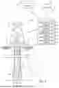
FIG. 1 is an illustration of a well site having a drilling rig positioned above a subterranean formation, in accordance with aspects of the present application;
FIG. 2 is a flow chart of a process for identifying, reporting, and correcting well thickness data, in accordance with aspects of the present application;
FIG. 3 is a series of plots illustrating clustering based on the signals and clustering based on the well completion file applied to the computed thickness per depth, in accordance with aspects of the present application;
FIG. 4 is a plot illustrating an indication of a user input error in the computed thickness, in accordance with aspects of the present application;
FIG. 5 is a plot illustrating an additional indication of a user input error in the computed thickness, in accordance with aspects of the present application;
FIG. 6 is a plot illustrating the effect of chrome pipes on the computed and corrected thicknesses, in accordance with aspects of the present application; and
FIG. 7 is a diagram of a GUI displaying the output of a report generated in FIG. 2, in accordance with aspects of the present application.
DETAILED DESCRIPTION
One or more specific embodiments of the present disclosure will be described below. In an effort to provide a concise description of these embodiments, all features of an actual implementation may not be described in the specification. It should be appreciated that in the development of any such actual implementation, as in any engineering or design project, numerous implementation-specific decisions must be made to achieve the developers' specific goals, such as compliance with system-related and business-related constraints, which may vary from one implementation to another. Moreover, it should be appreciated that such a development effort might be complex and time consuming, but would nevertheless be a routine undertaking of design, fabrication, and manufacture for those of ordinary skill having the benefit of this disclosure.
When introducing elements of various embodiments of the present disclosure, the articles “a,” “an,” “the,” and “said” are intended to mean that there are one or more of the elements. The terms “comprising,” “including,” and “having” are intended to be inclusive and mean that there may be additional elements other than the listed elements. Any examples of operating parameters and/or environmental conditions are not exclusive of other parameters/conditions of the disclosed embodiments.
Certain embodiments commensurate in scope with the present disclosure are summarized below. These embodiments are not intended to limit the scope of the disclosure, but rather these embodiments are intended only to provide a brief summary of certain disclosed embodiments. Indeed, the present disclosure may encompass a variety of forms that may be similar to or different from the embodiments set forth below.
The present disclosure relates to systems and methods for identification, reporting, and correction of well thickness data using a depth constraining, convergent machine learning clustering algorithm. In particular, a computing system may use an automated Learning Quality Control (LQC) algorithm, which identifies regions of thickness incoherence between known information (e.g., a well completion file) and measurements indicative of thickness obtained by an EMIT. For example, the computing system may receive computed thickness from the well, which is calculated by a user from the EMIT measurements. The computing system may cluster and normalize data from the well completion file and data from the EMIT measurements to generate a corrected well thickness and a corrected phase thickness, respectively. The computing system compares the computed thickness, the corrected well thickness, and the corrected phase thickness to determine whether the computed thickness and/or the corrected well thickness includes errors. The computing system may correct any errors in the computed thickness and/or the corrected well thickness. For example, the computing system may use values from the corrected phase thickness if the computed thickness is found to contain errors. The computing system may also output a report containing a list of the errors to a graphical user interface (GUI).
By way of introduction, FIG. 1 illustrates a well site 10 having a drilling rig 12 positioned above a subterranean formation 14 that includes one or more hydrocarbon reservoirs 16. During operation, a derrick and a hoisting apparatus of the drilling rig 12 may raise and lower a drilling string 18 into and out of a wellbore 20 of a well 22 to drill the wellbore 20 into the subterranean formation 14, as well as to position downhole well tools and equipment 26 within the wellbore 20 to facilitate completion and production operations of the well 22. For example, in certain operations, a fluid may be introduced into the well 22 through the drilling string 18, as illustrated by arrow 24, which may facilitate production of hydrocarbons from the well 22. The fluid and produced hydrocarbons may be returned to the surface 28 of the well site 10 (e.g., through the annulus between the drilling string 18 and the wellbore 20), as illustrated by arrow 30.
In some embodiments, the wellbore 20 may be encased in a well casing 32. As illustrated, the well casing 32 may include multiple sections with varying thickness due to use of different equipment and/or additional piping. For example, the well casing 32 has a first section 34 with a first thickness 36 and a second section 38 with a second thickness 40 greater than the first thickness 36. Production operations may wear, corrode, or deform the well casing 32, thereby decreasing a thickness of the well casing 32 and increasing an inner diameter 42 of the wellbore 20. Well casings 32 with less thickness may develop leaks, thereby causing unintended fluid movement or loss of containment of production flows. Therefore, one or more devices may be deployed within the wellbore 20 to determine an integrity of the well casing 32 by measuring the thickness of the well casing 32. In particular, the one or more devices may generate signals indicative of electromagnetic interactions with the well casing 32. The signals may be converted from a phase measurement (e.g., a raw measurement) to a thickness measurement (e.g., a computed thickness).
As such, the well site 10 may include a computing system 44 to receive and process the signals. The computing system 44 may be implemented via hardware (e.g., electronic circuitry) or a combination of hardware and programming (the combination comprising, e.g., at least one processor and instructions executable by the at least one processor and stored on at least one machine-readable storage medium). The computing system 44 may communicate with a database 46, a network 48, and the like. The network 48 may include any suitable network that facilitates communication between computing systems, electronic devices, and the like to enable the exchange of data and share resources between each other. The network 48 may include routers, switches, and other traffic directing devices to control the flow of data between senders and recipients. The network 48 may include a wired network, a wireless network, or both. By way of example, the network 48 may include a Local Area Network (LAN), a Wide Area Network (WAN), the Internet, an Intranet, and the like.
The computing system 44 may include a number of components to perform the various operations described herein. For example, the computing system 44 may include processing units 50 (e.g., one or more processors, one or more processing cores, processing circuitry, etc.), a memory 52, a communication component 54, a storage 56, input/output (I/O) ports 58, a display 60, and the like. Each of the processing units 50 may include multiple processor devices that may be of any type of computer processor or microprocessor capable of executing computer-executable code. Each processing unit 4 may also include multiple processors that may perform the operations described below. The communication component 54 may be a wireless or wired communication component that facilitates communication between the computing system 44, the database 46, the network 48, and any other suitable electronic device.
The memory 52 and the storage 56 may be any suitable article of manufacture that may serve as media to store processor-executable code, data, or the like. These articles of manufacture may represent computer-readable media (i.e., any suitable form of memory or storage) that may store the processor-executable code used by the processing units 50 to perform the presently disclosed techniques. The memory 52 and the storage 56 may represent non-transitory computer-readable media (e.g., any suitable form of memory or storage) that may store the processor-executable code used by the processing units 50 to perform various techniques described herein. It should be noted that non-transitory merely indicates that the media is tangible and not a signal.
The I/O ports 58 may provide access to one or more input devices, one or more displays 60, or the like to facilitate human or machine interaction with the computing system 44. The display 60 may operate to depict visualizations associated with software or executable code being processed by the processing units 50. In one embodiment, the display 60 may be a touch display capable of receiving inputs from a user of the computing system 44. The display 60 may be any suitable type of display, such as a liquid crystal display (LCD), plasma display, or an organic light emitting diode (OLED) display, for example. Additionally, in one embodiment, the display 60 may be provided in conjunction with a touch-sensitive mechanism (e.g., a touch screen) that may function as part of a control interface for the computing system 44.
Although the components of the computing system 44 are depicted with respect to the computing system 44, it should be noted that any other computing or processing device described herein may also include the same or similar components to perform, or facilitate performing, the various operations described herein. Moreover, it should be understood that the components described above are exemplary figures and the computing system 44 and other suitable computing systems may include additional or fewer components as detailed above.
As described above, the signals indicative of electromagnetic interactions may be converted from a phase measurement to a thickness measurement (e.g., a computed thickness). In particular, a user may convert the signals from a phase measurement (e.g., a raw measurement) for a given section of pipe to a thickness measurement. As such, incorrectly identifying the measurements corresponding to the given section of pipe (e.g., a depth shift to apply to the signals, the size and spacing of pipes in the wellbore 20) may cause errors in the result of the transformation. Additionally, certain materials, such as chrome (e.g., chromium, alloy) piping, may return signals that do not accurately reflect the thickness of the certain materials. To address this, FIG. 2 is a flowchart of process 100 for identifying, reporting, and correcting well thickness data. The process 100 may be implemented via the computing system 44 in the present embodiment. However, the process 100 may be implemented on any suitable computing system and/or processor. Although the process 100 is described in a particular order, it should be understood that the process 100 may be implemented in any suitable order.
In process block 102, the computing system 44 may access and/or receive signals indicative of electromagnetic interactions with a well casing of a well. The computing system 44 may access a database storing the signals or receive the signals as an input from a user. The signals may be obtained via inspections of the well casing using one or more electromagnetic interference tools (EMITs). The signals may include a series of phase measurements in degrees per depth.
In process block 104, the computing system 44 may access and/or receive a well completion file associated with the well. The computing system 44 may access a database storing the well completion file or receive the well completion file as an input from a user. The well completion file may be a dataset related to characteristics of the well as of time of completion of the well. For example, the well completion file may include a table. In each row of the table, the well completion file may include a starting depth, an ending depth, a number of pipes, a thickness, an indication of chrome pipes, and the like. In some embodiments, the well completion file may include a diagram of the data. The computing system 44 may convert the diagram to a table.
In block 106, the computing system 44 may determine a number of clusters (N) from the well completion file. A cluster may refer to a series of measurements that are within a threshold value of each other across a range of depths. For example, the computing system 44 may identify a value for N in the well completion file. As another example, the computing system 44 may set N as the number of rows.
In process block 108, the computing system 44 may access and/or receive computed thickness for the well. The computing system 44 may access a database storing the computed thickness or receive the computed thickness as an input from a user. The computing system 44 may proceed from process block 108 to process block 110 and process block 120. As such, in some embodiments, the computing system 44 may perform the following process blocks 110-118 and process blocks 120-130 in parallel.
In process block 110, the computing system 44 may cluster well thickness data (e.g., thickness values) from the well completion file into N clusters. The clusters may correspond to different sections of piping that may have different thicknesses. In particular, the computing system 44 may generate the clusters by determining N clusters of thickness measurements within a threshold value, a percentage value, or an error tolerance of each other. In some embodiments, the threshold value, the percentage value, or the error tolerance may be configurable by the user. The computing system 44 may use a k-means clustering algorithm or any other suitable advanced, unsupervised clustering algorithm to generate the clusters for the well completion file. The computing system 44 may input N as the anticipated number of clusters to the algorithm. The algorithm may return the starting depth and the ending depth of each of the N clusters. As such, the computing system 44 may separate the well thickness data into N clusters based on the data being between the starting depth and the ending depth of a particular cluster.
In process block 112, the computing system 44 may apply the clusters to the signals. That is, the computing system 44 may separate the phase measurements into the N clusters generated using the well thickness data. Each cluster includes the phase measurements between the starting depth and the ending depth associated with the particular cluster.
For each cluster, the computing system 44 may calculate a well thickness normalization factor (WTNF) using the signals and the well thickness data in block 114. The WTNF may be a coefficient (e.g., a multiplier). In some embodiments, the computing system 44 may use a median phase measurement of the signals and a median thickness measurement of the well thickness data for a given cluster to calculate the WTNF for the given cluster. For example, the WTNF for the given cluster may be the median thickness measurement divided by the median phase measurement. In some embodiments, the computing system 44 may use a physics modeling algorithm to calculate the WTNF for each cluster based on the signals and the well thickness data.
In block 116, the computing system 44 may obtain a corrected well thickness by applying the WTNF to the computed thickness. In particular, the computing system 44 may multiply each measurement of the computed thickness within a given cluster by the WTNF corresponding to the given cluster.
In block 118, the computing system 44 may flag (e.g., mark, identify, etc.) depths where a difference between the corrected well thickness and the computed thickness exceeds a first threshold. Thus, the computing system 44 may determine one or more ranges of depths where a percent difference of the corrected well thickness and the computed thickness exceeds 2.5%, 5%, 10%, 15%, and so on to flag. In some embodiments, the first threshold may be configurable by the user. The difference exceeding the first threshold may indicate that there is an error in the computed thickness at the identified range of depths and/or that the thickness of the well casing has changed since installation. Once the computing system 44 flags ranges of depths where the difference exceeds the first threshold, the computing system 44 may output the flagged ranges of depths, associated computed thickness, and associated corrected well thickness to a graphical user interface (GUI) as described in more detail with regard to FIG. 7. In some embodiments, if the range of depths includes all or most (e.g., greater than 60%, greater than 75%, greater than 95%, etc.) of the depths in a given cluster, the computing system 44 may additionally label differences exceeding an upper threshold (e.g., exceeding 10%, 15%, 25%, etc.) as an “Incorrect Pass.” If the range of depths includes a smaller portion (e.g., less than 30%, less than 15%, less than 5%, etc.) of the depths in a given cluster, the computing system 44 may additionally label differences exceeding an upper threshold (e.g., exceeding 10%, 15%, 25%, etc.) as an “Incorrect Pass/Depth Shift.”
In block 120, the computing system 44 may cluster the signals into 1.5(N) clusters. For example, if N is 6, the computing system 44 may cluster the signals into 9 clusters. In particular, the computing system 44 may generate the clusters by determining 1.5(N) clusters of phase measurements within a threshold value, a percentage value, or an error tolerance of each other. In some embodiments, the threshold value, the percentage value, or the error tolerance may be configurable by the user. The computing system 44 may use a k-means clustering algorithm or any other suitable advanced, unsupervised clustering algorithm to generate the clusters for the signals. The computing system 44 may input 1.5(N) as the anticipated number of clusters to the algorithm. By using more clusters than indicated in the well completion file, the computing system 44 ensures that the algorithm does not merge incorrectly merge clusters. The algorithm may return the starting depth and the ending depth of each of the 1.5(N) clusters. As such, the computing system 44 may separate the phase measurements into 1.5(N) clusters based on the data being between the starting depth and the ending depth of a particular cluster.
In block 122, the computing system 44 may merge the 1.5(N) clusters into merged clusters based on depth continuity. For example, the computing system 44 may merge clusters that are within a one pipe joint (e.g., within 30 feet, 40 feet, 55 feet, 75 feet, 100 feet, etc.) and are within a threshold number of degrees of each other (e.g., 0.5%, 1%, 2%, etc.). By merging the clusters, the computing system 44 ensures that the merged clusters correspond to different piping sections in the well casing. The computing system 44 may separate the phase measurements into the merged clusters based on the data being between the starting depth and the ending depth of a particular merged cluster.
In block 124, the computing system 44 may apply the merged clusters to the computed thickness. That is, the computing system 44 may separate the computed thickness into the merged clusters generated using the signals. Each merged cluster includes the computed thickness values between the starting depth and the ending depth associated with the particular merged cluster.
For each cluster, the computing system 44 may calculate a phase thickness normalization factor (PTNF) using the signals and the computed thickness in block 126. The PTNF may be a coefficient (e.g., a multiplier). In some embodiments, the computing system 44 may use a median phase measurement of the signals and a median computed thickness measurement for a given merged cluster to calculate the PTNF for the given cluster. For example, the PTNF for the given merged cluster may be the median computed thickness measurement divided by the median phase measurement. In some embodiments, the computing system 44 may use a physics modeling algorithm to calculate the PTNF for each merged cluster based on the signals and the computed thickness.
In block 128, the computing system 44 may obtain a corrected phase thickness by applying the PTNF to the computed thickness. In particular, the computing system 44 may multiply each measurement of the computed thickness within a given cluster by the PTNF corresponding to the given cluster.
In block 130, the computing system 44 may flag (e.g., mark, identify, etc.) depths where a difference between the corrected phase thickness and the computed thickness exceeds a second threshold. Thus, the computing system 44 may determine one or more ranges of depths where a percent difference between the corrected phase thickness and the computed thickness exceeds 2.5%, 5%, 10%, 15%, and so on to flag. The second threshold may be the same, smaller, or greater than the first threshold. The second threshold may be configurable by the user. The difference exceeding the second threshold may indicate that there is an error in the computed thickness and/or the depth shift. Once the computing system 44 flags ranges of depths where the difference exceeds the second threshold, the computing system 44 may output the flagged ranges of depths, associated computed thickness, and associated corrected phase thickness to the GUI as described in more detail with regard to FIG. 7. In some embodiments, if the range of depths includes all or most (e.g., greater than 60%, greater than 75%, greater than 95%, etc.) of the depths in a given merged cluster, the computing system 44 may additionally label differences exceeding an upper threshold (e.g., exceeding 10%, 15%, 25%, etc.) as an “Incorrect Pass.” If the range of depths includes a smaller portion (e.g., less than 30%, less than 15%, less than 5%, etc.) of the depths in a given merged cluster, the computing system 44 may additionally label differences exceeding an upper threshold (e.g., exceeding 10%, 15%, 25%, etc.) as an “Incorrect Pass/Depth Shift.”
In block 132, the computing system 44 may flag (e.g., mark, identify, etc.) depths where the corrected phase thickness aligns with the computed thickness and where a difference between the corrected phase thickness and the corrected well thickness exceeds a third threshold, thereby indicating that the corrected well thickness contains a user error. Thus, the computing system 44 may determine one or more ranges of depths where the percent difference between the corrected phase thickness and the computed thickness is below 2.5%, 1%, 0.5%, and so on. Additionally, the computing system 44 may determine additional ranges of depths of the one or more ranges of depths where the percent difference between the corrected phase thickness and the corrected well thickness exceeds 2.5%, 5%, 10%, 15%, and so on to flag. Once the computing system 44 determines which ranges of depths to flag, the computing system 44 may output the flagged ranges of depths, associated computed thickness, and associated corrected well thickness to GUI as described in more detail with regard to FIG. 7. In some embodiments, the computing system 44 may additionally label differences exceeding an upper threshold (e.g., exceeding 10%, 15%, 25%, etc.) as an “Incorrect Pass.”
In some embodiments, the computing system 44 may correct the thickness of the flagged depths. For example, the computing system 44 may set either thickness from the well completion data or the corrected phase thickness as the correct thickness of the flagged depths. In some embodiments, the user may decide whether to use the thickness from the well completion data or the corrected phase thickness. In some embodiments, the computing system 44 may determine which thickness to set as the correct thickness based on alignment of the corrected well thickness, the corrected phase thickness, the computed thickness, or any combination thereof. For example, if the corrected phase thickness and the computed thickness substantially align with each other and the corrected well thickness does not, the computing system 44 may set the corrected phase thickness as the correct thickness.
FIG. 3 is a series of plots illustrating clustering based on the signals and clustering based on the well completion file applied to the computed thickness per depth. The signal-based clustering plot 202 is a projection of the clusters determined from the signals onto the computed thickness per depth. Similarly, the well file-based clustering plot 204 is a projection of the clusters determined from the well completion file onto the computed thickness per depth. As discussed above, each cluster refers to a series of measurements between certain depths. Each cluster may correspond to a section of wellbore with a common thickness. Therefore, the plots 202, 204 include projections of the clusters at certain depths onto the thickness measurements of the computed thickness.
The signal-based clustering plot 202 includes six clusters. A first cluster 206 includes measurements between 10,500 feet and 11,000 feet. As indicated by the lower thickness measurements (e.g., approximately 0.15 inches), the first cluster 206 may be chrome piping. A second cluster 208 includes measurements between 10,000 feet and 10,500 feet. Similar to the first cluster 206, the lower thickness measurements (e.g., approximately 0.50 inches) may indicate the second cluster 208 is chrome piping. A third cluster 210 includes measurements of approximately 1 inch thickness between 4,800 feet and 4,900 feet and between 5,250 feet and 10,000 feet. As illustrated by the third cluster 210, the clusters may not be continuous. A fourth cluster 212 includes measurements of approximately 1.5 inch thickness between 4,900 feet and 5,250 feet. A fifth cluster 214 includes measurements of approximately 1.25 inch thickness between 3,900 feet and 4,800 feet. A sixth cluster 216 includes measurements of approximately 2 inch thickness between 500 feet and 3,900 feet.
The well file-based clustering plot 204 includes eight clusters. A first cluster 218 includes measurements between 10,500 feet and 11,000 feet. As indicated by the lower thickness measurements (e.g., approximately 0.15 inches), the first cluster 218 may be chrome piping. A second cluster 220 includes measurements between 10,000 feet and 10,500 feet. Similar to the first cluster 218, the lower thickness measurements (e.g., approximately 0.50 inches) may indicate the second cluster 220 is chrome piping. A third cluster 222 includes measurements of approximately 1 inch thickness between 5,250 feet and 10,000 feet. A fourth cluster 224 includes measurements of approximately 1.5 inch thickness between 4,900 feet and 5,250 feet. A fifth cluster 226 includes measurements of approximately 1.1 inch thickness between 4,800 feet and 4,900 feet. A sixth cluster 228 includes measurements of approximately 1.25 inch thickness between 3,900 feet and 4,800 feet. A seventh cluster 230 includes measurements of approximately 2 inch thickness between 600 feet and 3,900 feet. An eighth cluster 232 includes measurements of approximately 2.25 inch thickness between 500 feet and 600 feet.
In some instances, the signal-based clustering and well file-based clustering may produce similar clusters. For example, as illustrated, the first cluster 206 of plot 202 is similar to the first cluster 218 of plot 204, the second cluster 208 of plot 202 is similar to the second cluster 220 of plot 204, the fourth cluster 212 of plot 202 is similar to the fourth cluster 224 of plot 204, and the fifth cluster 214 of plot 202 is similar to the sixth cluster 228 of plot 204. The similar cluster pairs of the plot 202 and plot 204 may indicate different sections of wellbore having a substantially uniform thickness. However, as discussed above, signal-based clustering may include merging clusters based on depth continuity. As such, signal-based clustering may produce more or fewer clusters than well file-based clustering. For example, as illustrated, the third cluster 210 of plot 202 corresponds to the third cluster 222 and the fifth cluster 226 of plot 204. As another example, the sixth cluster 216 of plot 202 corresponds to the seventh cluster 230 and the eighth cluster 232.
FIG. 4 is a plot 300 illustrating an indication of a user input error in the computed thickness. The plot 300 includes a corrected well thickness 302, a corrected phase thickness 304, and a computed thickness 306. As illustrated, the corrected well thickness 302 and the corrected phase thickness 304 substantially align with each other. The computed thickness 306 substantially aligns with the corrected well thickness 302 and the corrected phase thickness 304 between 2997 feet and 3020 feet. However, between 2900 feet and 2997 feet, the computed thickness 306 diverges from the corrected well thickness 302 and the corrected phase thickness 304. In particular, the corrected well thickness 302 and the corrected phase thickness 304 have a median thickness of approximately 1.05 inches while the computed thickness 306 has a median thickness of approximately 1.3 inches, which is approximately 24% greater than the median thickness of the corrected well thickness 302 and the corrected phase thickness 304. Therefore, the difference in thickness between the computed thickness 306 and the corrected well thickness 302 and corrected phase thickness 304 indicates that there is an error in the computed thickness. For example, the difference in thickness may be attributable to a user assigning an incorrect thickness to the region between 2900 feet and 2997 feet when the phase measurements do not indicate a change in pipe size or dimensions for that depth. Because both the difference between the corrected well thickness 302 and the computed thickness 306 and the difference between the corrected phase thickness 304 and the computed thickness 306 are greater than a first and a second threshold (e.g., greater than 5% of the computed thickness 306), the computing system 44 may identify that there is a user error in the computed thickness 306 and output a report to a GUI including the depth between 2900 feet and 2997 feet. Additionally, because difference between the corrected well thickness 302 and the computed thickness 306 and the difference between the corrected phase thickness 304 and the computed thickness 306 are greater than upper thresholds (e.g., greater than 10% of the computed thickness 306), the report may include a flag of “Incorrect Pass” or “Incorrect Pass/Depth Shift” for the range of depths.
FIG. 5 is a plot 400 illustrating an additional indication of a user input error in the computed thickness. The plot 400 includes a corrected well thickness 402, a corrected phase thickness 404, and a computed thickness 406. As illustrated, the corrected phase thickness 404 and the computed thickness 406 substantially align with each other along a median thickness of 1.8 inches. However, the corrected well thickness 402 has a median thickness of 1.5 inches, which is 20% smaller than the median thickness of the corrected phase thickness 404 and the computed thickness 406. The substantial alignment of the corrected phase thickness 404 and the computed thickness 406 in combination with the difference between the corrected well thickness 402 and the corrected phase thickness 404 being greater than a third threshold (e.g., greater than 5% of the corrected well thickness 402), the plot 400 may indicate that there are errors in the well completion file and output a report to a GUI identifying the range of depths including the errors in the corrected well thickness 402. Additionally, because difference between the corrected well thickness 302 and the computed thickness 306 and the difference between the corrected phase thickness 304 and the computed thickness 306 are greater than upper thresholds (e.g., greater than 10% of the computed thickness 306), the report may include a flag of “Incorrect Pass” or “Incorrect Pass/Depth Shift” for the range of depths.
FIG. 6 is a plot 500 illustrating the effect of chrome (e.g., chromium, alloy) pipes on the computed and corrected thicknesses. As illustrated, plot 500 includes a corrected well thickness 502, a corrected phase thickness 504, and a computed thickness 506. The plot 500 includes three sections: a first section 508 between 1.035 feet and 1.06 feet and a second section 510 between 1 foot and 1.035 feet. In the first section 508, the corrected phase thickness 504 and the computed thickness 506 substantially align with each other along a median thickness of 0.12 inches. However, the corrected well thickness 502 has a median thickness of 0.40, which is 70% greater than the median thickness of the corrected phase thickness 504 and the computed thickness 506. Additionally, in the second section 510, the corrected phase thickness 504 and the computed thickness 506 substantially align with each other along a median thickness of 0.50 inches. However, the corrected well thickness 502 has a median thickness of 0.85, which is 40% greater than the median thickness of the corrected phase thickness 504 and the computed thickness 506. As discussed with regard to FIG. 5 above, the corrected well thickness 502 being more than a threshold difference from However, the first section 508 and the second section 510 may include ON chrome flags in the well completion file. Because the chrome flags are ON, the computing system 44 may use the corrected well thickness 502 as the correct thickness, include the sections 508, 510 in a report output to a GUI, and flag the sections 508, 510 in the report with a “Chrome Pipes” flag.
FIG. 7 is a diagram of a GUI 600 displaying the output of the report generated in FIG. 2. In particular, the GUI includes a table listing flagged depths for the corrected phase thickness 602 and flagged depths for the corrected well thickness 604. That is, the flagged depths for the corrected phase thickness 602 includes all depths at which the difference between the corrected phase thickness and the computed thickness exceeds the second threshold. The flagged depths for the corrected well thickness 604 includes all depths at which the difference between the corrected well thickness and the computed thickness exceeds the first threshold. Each entry in the table includes the starting depth, ending depth, the computed thickness median for the range of depths (e.g., the “OLD median”), the corrected phase thickness median for the range of depths or the corrected well thickness median for the range of depths respectively (e.g., the “NEW median”), and, optionally, a flag indicating “Incorrect Pass”, “Incorrect Pass/Depth Shift”, or “Chrome Pipes.”
Technical effects of the present disclosure relate to systems and methods for identification, reporting, and correction of well thickness data using a depth constraining, convergent machine learning clustering algorithm. In particular, a computing system may identify regions of thickness incoherence between known information (e.g., a well completion file) and measurements indicative of thickness obtained by an EMIT. For example, the computing system may receive computed thickness from the well, which is calculated by a user from the EMIT measurements. The computing system may cluster and normalize data from the well completion file and data from the EMIT measurements to generate a corrected well thickness and a corrected phase thickness, respectively. The computing system compares the computed thickness, the corrected well thickness, and the corrected phase thickness to determine whether the computed thickness and/or the corrected well thickness includes errors. As such, the computing system may determine whether there are errors in the computed thickness (e.g., inaccurate assignation of depth shift, inaccurate assignation of thickness, inaccurate pipe spacing and dimensions, etc.) and in the well completion file (e.g., inaccurate depth shift, inaccurate pipe spacing and dimensions, etc.). The computing system may correct any errors using the corrected phase thickness or the corrected well thickness. For example, the computing system may use values from the corrected well thickness if the computed thickness is found to contain errors. As another example, the computing system may use values from the corrected phase thickness if the corrected well thickness is found to contain errors. The computing system may also output a report containing a list of the errors to a graphical user interface (GUI).
The subject matter described in detail above may be defined by one or more clauses, as set forth below.
According to a first embodiment, a method includes receiving signals indicative of electromagnetic interactions with a well casing of a well, wherein the signals includes raw measurements across a first set of depths of the well, receiving a well completion file associated with the well, wherein the well completion file includes thickness values across a second set of depths of the well, receiving computed thickness measurements across a third set of depths of the well, clustering the raw measurements from the signals into a first plurality of clusters, wherein each cluster of the first plurality of clusters corresponds to a particular range of depths, merging a first cluster and a second cluster of the first plurality of clusters to generate a first plurality of merged clusters, wherein the first cluster and the second cluster are merged based on the first cluster being within one pipe joint of the second cluster and the first cluster being within a threshold number of degrees of each other, obtaining a corrected phase thickness using the first plurality of merged clusters, the signals, and the computed thickness measurements, clustering the thickness values from the well completion file into a second plurality of clusters, obtaining a corrected well thickness using the second plurality of clusters, the well completion file, and the computed thickness measurements, and identifying measurements of the corrected phase thickness and measurements of the corrected well thickness based on differences between each of the corrected phase thickness, the corrected well thickness, and the computed thickness measurements.
The method of the preceding clause, wherein a first number of clusters in the first plurality of clusters is greater than a second number of clusters in the second plurality of clusters.
The method of any preceding clause, wherein identifying measurements of the corrected phase thickness and measurements of the corrected well thickness based on differences between each of the corrected phase thickness, the corrected well thickness, and the computed thickness measurements includes determining a difference between the corrected phase thickness and the computed thickness measurements over a first range of depths exceeds a first threshold and outputting the first range of depths to a graphical user interface (GUI).
The method of any preceding clause, including determining the first range of depths includes more than a threshold percent of the depths in one of the merged clusters of the first plurality of merged clusters and outputting an “Incorrect Pass” flag to the GUI.
The method of any preceding clause, including outputting a median thickness of the corrected phase thickness over the first range of depths to the GUI as a corrected thickness.
The method of any preceding clause, wherein identifying measurements of the corrected phase thickness and measurements of the corrected well thickness based on differences between each of the corrected phase thickness, the corrected well thickness, and the computed thickness measurements includes determining a difference between the corrected well thickness and the computed thickness measurements over a second range of depths exceeds a second threshold and outputting the second range of depths to a graphical user interface (GUI).
The method of any preceding clause, wherein identifying measurements of the corrected phase thickness and measurements of the corrected well thickness based on differences between each of the corrected phase thickness, the corrected well thickness, and the computed thickness measurements includes determining a difference between the corrected phase thickness and the computed thickness measurements over a third range of depths is below a third threshold, determining a difference between the corrected phase thickness and the corrected well thickness over the third range of depths exceeds a fourth threshold, outputting the third range of depths to a graphical user interface (GUI), and outputting a median thickness of the corrected phase thickness over the third range of depths to the GUI as a corrected thickness.
The method of any preceding clause, wherein obtaining a corrected phase thickness using the first plurality of merged clusters, the signals, and the computed thickness measurements includes clustering the raw measurements of the signals according to the first plurality of merged clusters, clustering the computed thickness measurements according to the first plurality of merged clusters, calculating a phase thickness normalization factor for each cluster of the first plurality of merged clusters based on the clustered raw measurements and the clustered computed thickness measurements, wherein the phase thickness normalization factor is a coefficient, and multiplying each of the computed thickness measurements corresponding to a particular cluster by the phase thickness normalization factor for the particular cluster to obtain the corrected phase thickness.
The method of any preceding clause, wherein obtaining a corrected well thickness using the second plurality of clusters, the well completion file, and the computed thickness measurements includes clustering the thickness values of the well completion file according to the second plurality of clusters, clustering the computed thickness measurements according to the second plurality of clusters, calculating a well thickness normalization factor for each cluster of the second plurality of clusters based on the clustered thickness values of the well completion file and the clustered computed thickness measurements, wherein the well thickness normalization factor is a coefficient, and multiplying each of the computed thickness measurements corresponding to a particular cluster by the well thickness normalization factor for the particular cluster to obtain the corrected well thickness.
The method of any preceding clause, including determining a range of depths in the well completion file corresponding to a cluster of the second plurality of clusters includes an indication of chrome pipes, outputting the range of depths and a “Chrome Pipes” flag to a graphical user interface (GUI), and outputting a median thickness of the corrected well thickness over the range of depths to the GUI as a corrected thickness.
According to a second embodiment, a system includes a processing system, a memory, and instructions stored in the memory that, when executed by the processing system, cause the processing system to perform operations including: receiving signals indicative of electromagnetic interactions with a well casing of a well, wherein the signals includes raw measurements across a first set of depths of the well, receiving a well completion file associated with the well, wherein the well completion file includes thickness values across a second set of depths of the well, receiving computed thickness measurements across a third set of depths of the well, clustering the raw measurements from the signals into a first plurality of clusters, wherein each cluster of the first plurality of clusters corresponds to a particular range of depths, merging a first cluster and a second cluster of the first plurality of clusters to generate a first plurality of merged clusters, wherein the first cluster and the second cluster are merged based on the first cluster being within one pipe joint of the second cluster and the first cluster being within a threshold number of degrees of each other, obtaining a corrected phase thickness using the first plurality of merged clusters, the signals, and the computed thickness measurements, clustering the thickness values from the well completion file into a second plurality of clusters, obtaining a corrected well thickness using the second plurality of clusters, the well completion file, and the computed thickness measurements, and identifying measurements of the corrected phase thickness and measurements of the corrected well thickness based on differences between each of the corrected phase thickness, the corrected well thickness, and the computed thickness measurements.
The system of the preceding clause, wherein a first number of clusters in the first plurality of clusters is greater than a second number of clusters in the second plurality of clusters.
The system of any preceding clause, wherein identifying measurements of the corrected phase thickness and measurements of the corrected well thickness based on differences between each of the corrected phase thickness, the corrected well thickness, and the computed thickness measurements includes determining a difference between the corrected phase thickness and the computed thickness measurements over a first range of depths exceeds a first threshold, outputting the first range of depths to a graphical user interface (GUI), and outputting a median thickness of the corrected phase thickness over the first range of depths to the GUI as a corrected thickness.
The system of any preceding clause, wherein identifying measurements of the corrected phase thickness and measurements of the corrected well thickness based on differences between each of the corrected phase thickness, the corrected well thickness, and the computed thickness measurements includes determining a difference between the corrected well thickness and the computed thickness measurements over a second range of depths exceeds a second threshold and outputting the second range of depths to a graphical user interface (GUI).
The system of any preceding clause, wherein identifying measurements of the corrected phase thickness and measurements of the corrected well thickness based on differences between each of the corrected phase thickness, the corrected well thickness, and the computed thickness measurements includes determining a difference between the corrected phase thickness and the computed thickness measurements over a third range of depths is below a third threshold, determining a difference between the corrected phase thickness and the corrected well thickness over the third range of depths exceeds a fourth threshold, outputting the third range of depths to a graphical user interface (GUI), and outputting a median thickness of the corrected phase thickness over the third range of depths to the GUI as a corrected thickness.
The system of any preceding clause, wherein obtaining a corrected phase thickness using the first plurality of merged clusters, the signals, and the computed thickness measurements includes clustering the raw measurements of the signals according to the first plurality of merged clusters, clustering the computed thickness measurements according to the first plurality of merged clusters, calculating a phase thickness normalization factor for each cluster of the first plurality of merged clusters based on the clustered raw measurements and the clustered computed thickness measurements, wherein the phase thickness normalization factor is a coefficient, and multiplying each of the computed thickness measurements corresponding to a particular cluster by the phase thickness normalization factor for the particular cluster to obtain the corrected phase thickness.
A non-transitory, computer readable medium including a processing system and a memory storing instructions, which, when executed by the processing system, cause the processing system to perform operations including: receiving signals indicative of electromagnetic interactions with a well casing of a well, wherein the signals includes raw measurements across a first set of depths of the well, receiving a well completion file associated with the well, wherein the well completion file includes thickness values across a second set of depths of the well, receiving computed thickness measurements across a third set of depths of the well, clustering the raw measurements from the signals into a first plurality of clusters, wherein each cluster of the first plurality of clusters corresponds to a particular range of depths, merging a first cluster and a second cluster of the first plurality of clusters to generate a first plurality of merged clusters, wherein the first cluster and the second cluster are merged based on the first cluster being within one pipe joint of the second cluster and the first cluster being within a threshold number of degrees of each other, obtaining a corrected phase thickness using the first plurality of merged clusters, the signals, and the computed thickness measurements, clustering the thickness values from the well completion file into a second plurality of clusters, obtaining a corrected well thickness using the second plurality of clusters, the well completion file, and the computed thickness measurements, and identifying measurements of the corrected phase thickness and measurements of the corrected well thickness based on differences between each of the corrected phase thickness, the corrected well thickness, and the computed thickness measurements.
The non-transitory, computer readable medium of the preceding clause, wherein identifying measurements of the corrected phase thickness and measurements of the corrected well thickness based on differences between each of the corrected phase thickness, the corrected well thickness, and the computed thickness measurements includes determining a difference between the corrected phase thickness and the computed thickness measurements over a first range of depths exceeds a first threshold, outputting the first range of depths to a graphical user interface (GUI), and outputting a median thickness of the corrected phase thickness over the first range of depths to the GUI as a corrected thickness.
The non-transitory, computer readable medium of any preceding clause, wherein obtaining a corrected phase thickness using the first plurality of merged clusters, the signals, and the computed thickness measurements includes clustering the raw measurements of the signals according to the first plurality of merged clusters, clustering the computed thickness measurements according to the first plurality of merged clusters, calculating a phase thickness normalization factor for each cluster of the first plurality of merged clusters based on the clustered raw measurements and the clustered computed thickness measurements, wherein the phase thickness normalization factor is a coefficient, and multiplying each of the computed thickness measurements corresponding to a particular cluster by the phase thickness normalization factor for the particular cluster to obtain the corrected phase thickness.
The foregoing description, for purpose of explanation, has been described with reference to specific embodiments. However, the illustrative discussions above are not intended to be exhaustive or to limit the disclosure to the precise forms disclosed. Many modifications and variations are possible in view of the above teachings. Moreover, the order in which the elements of the methods described herein are illustrated and described may be re-arranged, and/or two or more elements may occur simultaneously. The embodiments were chosen and described in order to best explain the principals of the disclosure and its practical applications, to thereby enable others skilled in the art to best utilize the disclosure and various embodiments with various modifications as are suited to the particular use contemplated.
Finally, the techniques presented and claimed herein are referenced and applied to material objects and concrete examples of a practical nature that demonstrably improve the present technical field and, as such, are not abstract, intangible or purely theoretical. Further, if any claims appended to the end of this specification contain one or more elements designated as “means for [perform]ing [a function] . . . ” or “step for [perform]ing [a function] . . . ”, it is intended that such elements are to be interpreted under 35 U.S.C. 112(f). However, for any claims containing elements designated in any other manner, it is intended that such elements are not to be interpreted under 35 U.S.C. 112(f).
Claims
1. A method comprising:
receiving signals indicative of electromagnetic interactions with a well casing of a well, wherein the signals comprise raw measurements across a first set of depths of the well;
receiving a well completion file associated with the well, wherein the well completion file comprises thickness values across a second set of depths of the well;
receiving computed thickness measurements across a third set of depths of the well;
clustering the raw measurements from the signals into a first plurality of clusters, wherein each cluster of the first plurality of clusters corresponds to a particular range of depths;
merging a first cluster and a second cluster of the first plurality of clusters to generate a first plurality of merged clusters, wherein the first cluster and the second cluster are merged based on the first cluster being within one pipe joint of the second cluster and the first cluster being within a threshold number of degrees of each other;
obtaining a corrected phase thickness using the first plurality of merged clusters, the signals, and the computed thickness measurements;
clustering the thickness values from the well completion file into a second plurality of clusters;
obtaining a corrected well thickness using the second plurality of clusters, the well completion file, and the computed thickness measurements; and
identifying measurements of the corrected phase thickness and measurements of the corrected well thickness based on differences between each of the corrected phase thickness, the corrected well thickness, and the computed thickness measurements.
2. The method of claim 1, wherein a first number of clusters in the first plurality of clusters is greater than a second number of clusters in the second plurality of clusters.
3. The method of claim 1, wherein identifying measurements of the corrected phase thickness and measurements of the corrected well thickness based on differences between each of the corrected phase thickness, the corrected well thickness, and the computed thickness measurements comprises:
determining a difference between the corrected phase thickness and the computed thickness measurements over a first range of depths exceeds a first threshold; and
outputting the first range of depths to a graphical user interface (GUI).
4. The method of claim 3, comprising:
determining the first range of depths comprises more than a threshold percent of the depths in one of the merged clusters of the first plurality of merged clusters; and
outputting an “Incorrect Pass” flag to the GUI.
5. The method of claim 3, comprising:
determining the first range of depths comprises less than a threshold percent of the depths in one of the merged clusters of the first plurality of merged clusters; and
outputting an “Incorrect Pass/Depth Shift” flag to the GUI.
6. The method of claim 1, wherein the raw measurements comprise phase measurements, attenuation measurements, real parts and imaginary parts of complex valued measurements, or any combination thereof.
7. The method of claim 1, wherein identifying measurements of the corrected phase thickness and measurements of the corrected well thickness based on differences between each of the corrected phase thickness, the corrected well thickness, and the computed thickness measurements comprises:
determining a difference between the corrected well thickness and the computed thickness measurements over a second range of depths exceeds a second threshold; and
outputting the second range of depths to a graphical user interface (GUI).
8. The method of claim 1, wherein identifying measurements of the corrected phase thickness and measurements of the corrected well thickness based on differences between each of the corrected phase thickness, the corrected well thickness, and the computed thickness measurements comprises:
determining a difference between the corrected phase thickness and the computed thickness measurements over a third range of depths is below a third threshold;
determining a difference between the corrected phase thickness and the corrected well thickness over the third range of depths exceeds a fourth threshold;
outputting the third range of depths to a graphical user interface (GUI); and
outputting a median thickness of the corrected phase thickness over the third range of depths to the GUI as a corrected thickness.
9. The method of claim 1, wherein obtaining a corrected phase thickness using the first plurality of merged clusters, the signals, and the computed thickness measurements comprises:
clustering the raw measurements of the signals according to the first plurality of merged clusters;
clustering the computed thickness measurements according to the first plurality of merged clusters;
calculating a phase thickness normalization factor for each cluster of the first plurality of merged clusters based on the clustered raw measurements and the clustered computed thickness measurements, wherein the phase thickness normalization factor is a coefficient; and
multiplying each of the computed thickness measurements corresponding to a particular cluster by the phase thickness normalization factor for the particular cluster to obtain the corrected phase thickness.
10. The method of claim 1, wherein obtaining a corrected well thickness using the second plurality of clusters, the well completion file, and the computed thickness measurements comprises:
clustering the thickness values of the well completion file according to the second plurality of clusters;
clustering the computed thickness measurements according to the second plurality of clusters;
calculating a well thickness normalization factor for each cluster of the second plurality of clusters based on the clustered thickness values of the well completion file and the clustered computed thickness measurements, wherein the well thickness normalization factor is a coefficient; and
multiplying each of the computed thickness measurements corresponding to a particular cluster by the well thickness normalization factor for the particular cluster to obtain the corrected well thickness.
11. The method of claim 1, comprising:
determining a range of depths in the well completion file corresponding to a cluster of the second plurality of clusters includes an indication of chrome pipes;
outputting the range of depths and a “Chrome Pipes” flag to a graphical user interface (GUI); and
outputting a median thickness of the corrected well thickness over the range of depths to the GUI as a corrected thickness.
12. A system comprising:
a processing system;
a memory; and
instructions stored in the memory that, when executed by the processing system, cause the processing system to perform operations comprising:
receiving signals indicative of electromagnetic interactions with a well casing of a well, wherein the signals comprise raw measurements across a first set of depths of the well;
receiving a well completion file associated with the well, wherein the well completion file comprises thickness values across a second set of depths of the well;
receiving computed thickness measurements across a third set of depths of the well;
clustering the raw measurements from the signals into a first plurality of clusters, wherein each cluster corresponds to a particular range of depths;
merging a first cluster and a second cluster of the first plurality of clusters to generate a first plurality of merged clusters, wherein the first cluster and the second cluster are merged based on the first cluster being within one pipe joint of the second cluster and the first cluster being within a threshold number of degrees of each other;
obtaining a corrected phase thickness using the first plurality of merged clusters, the signals, and the computed thickness measurements;
clustering the thickness values from the well completion file into a second plurality of clusters;
obtaining a corrected well thickness using the second plurality of clusters, the well completion file, and the computed thickness measurements; and
identifying measurements of the corrected phase thickness and measurements of the corrected well thickness based on differences between each of the corrected phase thickness, the corrected well thickness, and the computed thickness measurements.
13. The system of claim 12, wherein a first number of clusters in the first plurality of clusters is greater than a second number of clusters in the second plurality of clusters.
14. The system of claim 12, wherein identifying measurements of the corrected phase thickness and measurements of the corrected well thickness based on differences between each of the corrected phase thickness, the corrected well thickness, and the computed thickness measurements comprises:
determining a difference between the corrected phase thickness and the computed thickness measurements over a first range of depths exceeds a first threshold;
outputting the first range of depths to a graphical user interface (GUI); and
outputting a median thickness of the corrected phase thickness over the first range of depths to the GUI as a corrected thickness.
15. The system of claim 12, wherein identifying measurements of the corrected phase thickness and measurements of the corrected well thickness based on differences between each of the corrected phase thickness, the corrected well thickness, and the computed thickness measurements comprises:
determining a difference between the corrected well thickness and the computed thickness measurements over a second range of depths exceeds a second threshold; and
outputting the second range of depths to a graphical user interface (GUI).
16. The system of claim 12, wherein identifying measurements of the corrected phase thickness and measurements of the corrected well thickness based on differences between each of the corrected phase thickness, the corrected well thickness, and the computed thickness measurements comprises:
determining a difference between the corrected phase thickness and the computed thickness measurements over a third range of depths is below a third threshold;
determining a difference between the corrected phase thickness and the corrected well thickness over the third range of depths exceeds a fourth threshold;
outputting the third range of depths to a graphical user interface (GUI); and
outputting a median thickness of the corrected phase thickness over the third range of depths to the GUI as a corrected thickness.
17. The system of claim 12, wherein obtaining a corrected phase thickness using the first plurality of merged clusters, the signals, and the computed thickness measurements comprises:
clustering the raw measurements of the signals according to the first plurality of merged clusters;
clustering the computed thickness measurements according to the first plurality of merged clusters;
calculating a phase thickness normalization factor for each cluster of the first plurality of merged clusters based on the clustered raw measurements and the clustered computed thickness measurements, wherein the phase thickness normalization factor is a coefficient; and
multiplying each of the computed thickness measurements corresponding to a particular cluster by the phase thickness normalization factor for the particular cluster to obtain the corrected phase thickness.
18. A non-transitory, computer readable medium comprising a processing system and a memory storing instructions which, when executed by the processing system, cause the processing system to perform operations comprising:
receiving signals indicative of electromagnetic interactions with a well casing of a well, wherein the signals comprise raw measurements across a first set of depths of the well;
receiving a well completion file associated with the well, wherein the well completion file comprises thickness values across a second set of depths of the well;
receiving computed thickness measurements across a third set of depths of the well;
clustering the raw measurements from the signals into a first plurality of clusters, wherein each cluster corresponds to a particular range of depths;
merging a first cluster and a second cluster of the first plurality of clusters to generate a first plurality of merged clusters, wherein the first cluster and the second cluster are merged based on the first cluster being within one pipe joint of the second cluster and the first cluster being within a threshold number of degrees of each other;
obtaining a corrected phase thickness using the first plurality of merged clusters, the signals, and the computed thickness measurements;
clustering the thickness values from the well completion file into a second plurality of clusters;
obtaining a corrected well thickness using the second plurality of clusters, the well completion file, and the computed thickness measurements; and
identifying measurements of the corrected phase thickness and measurements of the corrected well thickness based on differences between each of the corrected phase thickness, the corrected well thickness, and the computed thickness measurements.
19. The non-transitory, computer readable medium of claim 18, wherein identifying measurements of the corrected phase thickness and measurements of the corrected well thickness based on differences between each of the corrected phase thickness, the corrected well thickness, and the computed thickness measurements comprises:
determining a difference between the corrected phase thickness and the computed thickness measurements over a first range of depths exceeds a first threshold;
outputting the first range of depths to a graphical user interface (GUI); and
outputting a median thickness of the corrected phase thickness over the first range of depths to the GUI as a corrected thickness.
20. The non-transitory, computer readable medium of claim 18, wherein obtaining a corrected phase thickness using the first plurality of merged clusters, the signals, and the computed thickness measurements comprises:
clustering the raw measurements of the signals according to the first plurality of merged clusters;
clustering the computed thickness measurements according to the first plurality of merged clusters;
calculating a phase thickness normalization factor for each cluster of the first plurality of merged clusters based on the clustered raw measurements and the clustered computed thickness measurements, wherein the phase thickness normalization factor is a coefficient; and
multiplying each of the computed thickness measurements corresponding to a particular cluster by the phase thickness normalization factor for the particular cluster to obtain the corrected phase thickness.
Images & Drawings included:


Sources:
- United States Patent and Trademark Office - verify current appl. status at the USPTO↗
Recent applications in this class:
- » 20260176958 2026-06-25
DATA-DRIVEN CONSTRAINED MODEL FOR CORROSION INSPECTION TOOLS - » 20260176956 2026-06-25
SMART PLUNGERS MEASURING WELLBORE BUILDUP - » 20260153026 2026-06-04
DOWNHOLE ENVIRONMENT EVALUATION BASED ON MONITORING DEGRADABLE DEVICES - » 20260002435 2026-01-01
DUMMY WELL SET-UP FOR TESTING LOGGING TOOLS - » 20250369339 2025-12-04
PREDICTION OF SCREEN-OUT EVENT IN A WELLBORE FROM RESISTANCE MEASURED BASED ON PRESSURE PULSE - » 20250320810 2025-10-16
MAGNETIC FOCUSING SCHEME FOR FLUX LEAKAGE MEASUREMENT - » 20250250894 2025-08-07
CONFORMAL SPACE FILLING COILS - » 20250116186 2025-04-10
METHOD AND SYSTEM FOR AUTOMATED MONITORING OF THE OPERATIONAL PARAMETERS AND SEVERITY OF THE PHENOMENON OF CO2 STRESS CORROSION CRACKING IN FLEXIBLE PIPELINES - » 20250116185 2025-04-10
PROCESSES FOR MONITORING CORROSION AND CARRYING OUT OPERATIONAL PLANS USING SAME - » 20250101856 2025-03-27
WELLBORE DEPOSITION MONITORING TOOL