COMPRESSED CARBON DIOXIDE ENERGY STORAGE SYSTEM AND METHOD COMBINED WITH AIR SEPARATION TECHNOLOGY
US20260176984A1
2026-06-25
19/274,572
2025-07-20
Smart Summary: A system is designed to store energy using compressed carbon dioxide and air separation technology. It separates air into nitrogen, oxygen, and carbon dioxide, while also producing waste nitrogen. During times when energy demand is low, the system compresses carbon dioxide, capturing heat and pressure energy. When energy demand is high, this stored energy is converted back into electricity to power the air separation process and other devices. The waste nitrogen helps provide heat, while nitrogen and oxygen are used to cool the system. 🚀 TL;DR
Abstract:
A compressed carbon dioxide energy storage system and method combined with an air separation technology are provided. The system includes an air separation assembly, separating air to generate nitrogen, oxygen, carbon dioxide and waste nitrogen; an energy storage assembly, using carbon dioxide as a working medium, compressing carbon dioxide and collecting heat energy and pressure energy generated during compressing the carbon dioxide in off-peak period; an energy release assembly, converting the collected heat energy and pressure energy to electric energy, to supply to the air separation assembly and an electrical device in peak period. The waste nitrogen is used as a heat source for the air separation assembly, the energy storage assembly and the energy release assembly to provide heat energy, and nitrogen/oxygen is used as a cool source for the air separation assembly, the energy storage assembly and the energy release assembly to provide cool energy.
Inventors:
- Ding Wang 4 🇨🇳 Xi'an, China
- Di ZHANG 4 🇨🇳 Xi'an, China
- Yonghui XIE 2 🇨🇳 Xi'an, China
- Xikai Liu 1 🇨🇳 Xi'an, China
Applicant:
Interested in similar patents?
Get notified when new applications in this technology area are published.
Classification:
F01K3/006 » CPC main
Plants characterised by the use of steam or heat accumulators, or intermediate steam heaters, therein Accumulators and steam compressors
F25J3/04163 » CPC further
Processes or apparatus for separating the constituents of gaseous or liquefied gaseous mixtures involving the use of liquefaction or solidification by rectification, i.e. by continuous interchange of heat and material between a vapour stream and a liquid stream for air; Purification and (pre-)cooling of the feed air; recuperative heat-exchange with product streams Hot end purification of the feed air
F25J3/04412 » CPC further
Processes or apparatus for separating the constituents of gaseous or liquefied gaseous mixtures involving the use of liquefaction or solidification by rectification, i.e. by continuous interchange of heat and material between a vapour stream and a liquid stream for air using a dual pressure main column system in a classical double column flowsheet, i.e. with thermal coupling by a main reboiler-condenser in the bottom of low pressure respectively top of high pressure column
F25J2205/04 » CPC further
Processes or apparatus using other separation and/or other processing means using simple phase separation in a vessel or drum in the feed line, i.e. upstream of the fractionation step
F25J2240/04 » CPC further
Processes or apparatus involving steps for expanding of process streams; Expansion of a process fluid in a work-extracting turbine (i.e. isentropic expansion), e.g. of the feed stream Multiple expansion turbines in parallel
F25J2260/80 » CPC further
Coupling of processes or apparatus to other units; Integrated schemes Integration in an installation using carbon dioxide, e.g. for EOR, sequestration, refrigeration etc.
F01K3/00 IPC
Plants characterised by the use of steam or heat accumulators, or intermediate steam heaters, therein
F01K3/00 IPC
Steam engine plants
F25J3/04 IPC
Processes or apparatus for separating the constituents of gaseous or liquefied gaseous mixtures involving the use of liquefaction or solidification by rectification, i.e. by continuous interchange of heat and material between a vapour stream and a liquid stream for air
Description
CROSS-REFERENCE TO RELATED APPLICATION
This application claims priority to Chinese Patent Application No. 202411879029.1, filed on Dec. 19, 2024, which is herein incorporated by reference in its entirety.
TECHNICAL FIELD
The disclosure relates to the field of energy storage technologies, and more particularly to a compressed carbon dioxide energy storage system and method combined with an air separation technology.
BACKGROUND
With a rapid development of renewable energy, the power system is facing a challenge of how to store and utilize energy efficiently. A compressed carbon dioxide energy storage system is a new type of energy storage technology, which can convert electrical energy into internal energy when there is an oversupply of electricity, compress and store the internal energy with a help of carbon dioxide, and then release the stored energy at a peak of electricity demand.
However, in order to improve an overall energy storage density of a current compressed carbon dioxide energy storage system, it is usually necessary to convert gaseous carbon dioxide into liquid carbon dioxide for storage, and additional heat and cold sources are also required. This conversion process usually consumes a large amount of electricity and other energy, resulting in high operating costs for the compressed carbon dioxide energy storage system and low overall energy conversion efficiency of the system.
SUMMARY
An objective of the disclosure is to provide a compressed carbon dioxide energy storage system and method combined with an air separation technology. The entire system does not need additional heat and cold sources, which reduces power consumption, improves system efficiency, reduces operating costs, and has advantages of high energy conversion efficiency and high resource utilization.
In order to achieve the above technical objective, specifical technical solutions of the disclosure are as follows.
A compressed carbon dioxide energy storage system combined with an air separation technology includes a gaseous carbon dioxide storage tank, a liquid carbon dioxide storage tank, an energy storage assembly, an energy release assembly and an air separation assembly. The energy storage assembly and the energy release assembly are respectively disposed between the gaseous carbon dioxide storage tank and the liquid carbon dioxide storage tank. The energy storage assembly includes a preheater, a first compressor and a condenser sequentially connected in that order, the first compressor is configured to compress carbon dioxide, and the condenser is configured to condense the carbon dioxide. The energy release assembly includes a first evaporator, a first turbine and a first cooler sequentially connected in that order. An output axis of the first turbine is connected to an input axis of a generator, the generator is configured to generate electric energy, and the first cooler is configured to cool carbon dioxide entering the gaseous carbon dioxide cylinder. The air separation assembly includes an air pretreatment component and a separation column. The separation column is connected to an output end of the air pretreatment component, the separation column is configured to separate air to generate nitrogen, oxygen, and waste nitrogen, the nitrogen and the oxygen each are a cold source, and the waste nitrogen is a heat source. The cool source is supplied to the condenser, the first cooler and the air pretreatment component individually through pipelines, the heat source is supplied to the preheater and the first evaporator individually through the pipelines, and the electric energy generated on the generator is supplied to the air pretreatment component.
In an embodiment, the air pretreatment component includes a second compressor, a second cooler, a gas-liquid separator and a first expansion valve, and the second compressor, the second cooler and the gas-liquid separator are connected. A gas phase outlet of the gas-liquid separator is connected to the first expansion valve, and an input end of the separation column is connected to the first expansion valve. The second compressor is configured to pressurize and heat the air, the second cooler is configured to cool the air, the gas-liquid separator is configured to separate liquid water and the carbon dioxide from gaseous air, and the first expansion valve is configured to expand and cool the gaseous air. The cool source is connected to a cooling inlet of the second cooler through the pipelines, a cooling outlet of the second cooler is vented, and the generator is electrically connected to the second compressor.
In an embodiment, the air pretreatment component further includes an air purifier and a first control valve. The air purifier is disposed on an air inlet of the second compressor, and the air purifier is configured to filter to remove impurifies from the air. The first control valve is disposed on an air inlet of the air purifier, and the first control valve is configured to control on-off of the air.
In an embodiment, the compressed carbon dioxide energy storage system further includes a carbon dioxide supplement assembly. The carbon dioxide supplement assembly includes a dryer, a second control valve, a second expansion valve and a second evaporator sequentially connected in that order. The dryer is connected to a liquid phase outlet of the gas-liquid separator, and the second evaporator is connected to the gaseous carbon dioxide storage tank. The heat source is connected to a heating inlet of the second evaporator through the pipelines, and a heating outlet of the second evaporator is vented.
In an embodiment, the compressed carbon dioxide energy storage system further includes a carbon dioxide storage assembly. The carbon dioxide storage assembly includes a third control valve, a first booster pump and a carbon dioxide storage tank sequentially connected in that order. The first booster pump is configured to pressurize liquid carbon dioxide, and the third control valve is connected to an outlet of the dryer.
In an embodiment, the compressed carbon dioxide energy storage system further includes a heat exchange assembly. The heat exchange assembly includes a cool storage tank, a first heat exchanger, a second heat exchanger and a heat storage tank. The first heat exchanger is disposed between the first compressor and the condenser, and the second heat exchanger is disposed between the first evaporator and the first turbine. The cool storage tank and the heat storage tank each are configured to store with a heat storage medium, the cool storage tank and the heat storage tank form a heat exchange loop between the first heat exchanger and the second heat exchanger, and the heat storage medium is configured to flow in the heat exchange loop.
In an embodiment, the energy storage assembly further includes a third compressor and a third heat exchanger. The first heat exchanger, the third compressor, the third heat exchanger and the condenser are sequentially connected in that order, and the third heat exchanger is connected to the cool storage tank and the heat storage tank individually.
In an embodiment, the energy release assembly further includes a fourth heat exchanger and a second turbine. The first evaporator, the fourth heat exchanger, the second turbine and the second heat exchanger are sequentially connected in that order, and the fourth heat exchanger is connected to the cool storage tank and the heat storage tank individually. An output axis of the second turbine is connected to the input axis of the generator, the generator is configured to generate the electric energy, and the generator is electrically connected to the second compressor.
A compressed carbon dioxide energy storage method, applied to the compressed carbon dioxide energy storage system combined with the air separation technology, includes:
-
- separating, by using the air separation assembly, the air to generate the nitrogen, the oxygen, the carbon dioxide and the waste nitrogen, taking the waste nitrogen as the heat source for the air separation assembly, the energy storage assembly and the energy release assembly, and taking the nitrogen as the cool source for the air separation assembly, the energy storage assembly and the energy release assembly, or taking the oxygen as the cool source for the air separation assembly, the energy storage assembly and the energy release assembly;
- in a period of off-peak electricity usage, compressing, by the energy storage assembly, the carbon dioxide, and collecting, by the energy storage assembly, heat energy and pressure energy generated during compressing the carbon dioxide; and
- in a period of peak electricity usage, converting, by the energy release assembly, the heat energy and pressure energy collected by the energy storage assembly to electric energy, to supply to the air separation assembly and an electrical device.
Compared with the related art, in the compressed carbon dioxide energy storage system and method combined with the air separation technology of the disclosure, the system has three different working assemblies, which are the energy storage assembly, the energy release assembly and the air separation assembly. The air separation assembly generates the heat source and the cold sources, which are supplied to the energy storage assembly and the energy release assembly respectively, and the electric energy converted from the working medium after the energy storage and energy release process is supplied to the air separation assembly. The entire system does not need to introduce additional heat sources and cold sources. Since the electric energy generated by the energy release assembly can be supplemented for use in the air separation assembly, no excessive external electric energy input is required, which reduces the overall consumption of electric energy and improves the system efficiency. In addition, due to a simple structure of the system, air is easy to obtain as a source of separation object and low cost, so that the energy storage system is no longer dependent on a specific geographical environment and can be used in a wider geographical area. It has advantages of low power consumption, high energy conversion efficiency, high resource utilization, and low operating cost. The system is highly practical and worthy of promotion.
BRIEF DESCRIPTION OF DRAWINGS
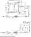
FIG. 1 illustrates a schematic structural diagram 1 of an entire compressed carbon dioxide energy storage system of the disclosure.
FIG. 2 illustrates a schematic structural diagram of an air separation assembly of the disclosure.
FIG. 3 illustrates a schematic structural diagram 1 of an energy storage assembly of the disclosure.
FIG. 4 illustrates a schematic structural diagram 2 of the energy storage assembly of the disclosure.
FIG. 5 illustrates a schematic structural diagram 1 of an energy release assembly of the disclosure.
FIG. 6 illustrates a schematic structural diagram 2 of the energy release assembly of the disclosure.
FIG. 7 illustrates a schematic structural diagram 2 of the entire compressed carbon dioxide energy storage system of the disclosure.
DESCRIPTION OF REFERENCE SIGNS
1—air purifier; 2—second compressor; 3—second cooler; 4—gas-liquid separator; 5—dryer; 6—second expansion valve; 7—second evaporator; 8—first expansion valve; 9—separation column; 10—second booster pump; 11—argon storage tank; 12—first booster pump; 13—carbon dioxide storage tank; 14—gaseous carbon dioxide storage tank; 15—preheater; 16—first compressor; 17—first heat exchanger; 18—third compressor; 19—third heat exchanger; 20—condenser; 21—liquid carbon dioxide storage tank; 22—first evaporator; 23—fourth heat exchanger; 24—second turbine; 25—second heat exchanger; 26—first turbine; 27—first cooler; 28—cool storage tank; 29—heat storage tank; 30—first control valve; 31—second control valve; 32—third control valve; 33—fourth control valve; 34—fifth control valve; 35—sixth control valve; 36—seventh control valve; 37—eighth control valve; 38—pipeline; G—generator; M—start motor.
DETAILED DESCRIPTION OF EMBODIMENTS
In order to improve an overall energy storage density of a current compressed carbon dioxide energy storage system, it is usually necessary to convert gaseous carbon dioxide into liquid carbon dioxide for storage, and additional heat and cold sources are also required. This conversion process usually consumes a large amount of electricity and other energy, resulting in high operating costs for the compressed carbon dioxide energy storage system and low overall energy conversion efficiency of the system.
Aiming at the above technical problem, the disclosure provides a new compressed carbon dioxide energy storage system and method combined with an air separation technology.
In order to enable those skilled in the art to better understand and implement the technical solutions of the disclosure, the technical solutions of the disclosure will be clearly and fully described below in conjunction with FIGS. 1 to 7.
In the description of the disclosure, it should be understood that terms “center”, “longitudinal”, “lateral”, “length”, “width”, “thickness”, “up”, “down”, “front”, “back”, “left”, “right”, “vertical”, “horizontal”, “top”, “bottom”, “inside”, “outside”, “clockwise”, “counterclockwise”, “axial”, “radial” and “circumferential” indicating orientations or positional relationships based on the orientations or positional relationships shown in the drawings, are only for convenience of describing the disclosure and simplifying the description, and do not indicate or imply that the device or element referred to must have a specific orientation, be constructed and operated in a specific orientation, and therefore should not be understood as limiting the disclosure.
In addition, it should be further noted that, in the description of embodiments of the disclosure, unless otherwise specified, “/” means or, for example, A/B can mean A or B, “and/or” in the text is merely a description of an association relationship of associated objects, indicating that three relationships may exist, for example, A and/or B can mean: A exists alone, A and B exist at the same time, and B exists alone. In addition, in the description of the embodiments of the disclosure, “multiple” refers to two or more than two.
The following terms “first”, “second”, “third” and “fourth” are used for descriptive purposes only and should not be understood as suggesting or implying relative importance or implicitly indicating the number of technical features indicated. Therefore, features defined as “first”, “second”, “third” and “fourth” may explicitly or implicitly include one or more of the features. In the description of the disclosure, unless otherwise specified, “plurality” means two or more.
Embodiment 1
As shown in FIG. 1, the disclosure provides a compressed carbon dioxide energy storage system combined with an air separation technology, including a gaseous carbon dioxide storage tank 14, a liquid carbon dioxide storage tank 21, an energy storage assembly, an energy release assembly and an air separation assembly. The gaseous carbon dioxide cylinder 14 is configured to store gaseous carbon dioxide, and the liquid carbon dioxide cylinder 21 is configured to store liquid carbon dioxide.
Specifically, as shown in FIG. 3, the energy storage assembly is disposed between the gaseous carbon dioxide storage tank 14 and the liquid carbon dioxide storage tank 21. The energy storage assembly includes a preheater 15, a first compressor 16 and a condenser 20 sequentially connected in that order. The first compressor 16 is configured to compress carbon dioxide, and the condenser 20 is configured to condense the carbon dioxide. The preheater 15 is connected to the gaseous carbon dioxide storage tank 14 through a fifth control valve 34, and the condenser 20 is connected to the liquid carbon dioxide storage tank 21.
Specifically, as shown in FIG. 5, the energy release assembly is disposed between the gaseous carbon dioxide storage tank 14 and the liquid carbon dioxide storage tank 21. The energy release assembly includes a first evaporator 22, a first turbine 26 and a first cooler 27 sequentially connected in that order. An output axis of the first turbine 26 is connected to an input axis of a generator G, the generator G is configured to generate electric energy, and the first cooler 27 is configured to cool the carbon dioxide entering the gaseous carbon dioxide storage tank 14. The first evaporator 22 is connected to the liquid carbon dioxide storage tank 21 through a sixth control valve 35, and the first cooler 27 is connected to the gaseous carbon dioxide storage tank 14.
Specifically, the compressed carbon dioxide energy storage system further includes a heat exchange assembly. The heat exchange assembly includes a cool storage tank 28, a first heat exchanger 17, a second heat exchanger 25 and a heat storage tank 29. The first heat exchanger 17 is disposed between the first compressor 16 and the condenser 20, and the second heat exchanger 25 is disposed between the first evaporator 22 and the first turbine 26. The cool storage tank 28 and the heat storage tank 29 each are configured to store with a heat storage medium, the cool storage tank 28 and the heat storage tank 29 form a heat exchange loop between the first heat exchanger 17 and the second heat exchanger 25, and the heat storage medium is configured to flow in the heat exchange loop, thereby achieving the entire heat cycle.
As shown in FIG. 2, the air separation assembly includes an air pretreatment component and a separation column 9. The air pretreatment component separates the air into a gas phase and a liquid phase. The separation column 9 is connected to a gas phase output end of the air pretreatment component, and the separation column 9 is configured to separate the air to generate nitrogen, oxygen, and waste nitrogen. The nitrogen and the oxygen each are a cold source, and the waste nitrogen is a heat source. The cool source is supplied to the condenser 20, the first cooler 27 and the air pretreatment component individually through pipelines 38, the heat source is supplied to the preheater 15 and the first evaporator 22 individually through the pipelines 38, and the electric energy generated on the generator G is supplied to the air pretreatment component.
Specifically, the air pretreatment component includes a second compressor 2, a second cooler 3, a gas-liquid separator 4 and a first expansion valve 8, and the second compressor 2, the second cooler 3 and the gas-liquid separator 4 are connected. A gas phase outlet of the gas-liquid separator 4 is connected to the first expansion valve 8, and an input end of the separation column 9 is connected to the first expansion valve 8. The second compressor 2 is configured to pressurize and heat the air. The second cooler 3 is configured to convert steam and carbon dioxide in the pressurized air into liquid, and input them into the gas-liquid separator for gas-liquid separation. The gas-liquid separator 4 is configured to separate liquid water and the carbon dioxide from gaseous air. The first expansion valve 8 is configured to expand and cool the gaseous air. The cool source is connected to a cooling inlet of the second cooler 3 through the pipelines 38, a cooling outlet of the second cooler 3 is vented, so that the cool source is directly discharged to the air after completing the cooling of the second cooler 3. The generator G is electrically connected to the second compressor 2, thereby supplying the electric energy generated on the generator G to the second compressor 2, so that the system can be self-sufficient and reduce external power supply.
In an embodiment, in order to remove impurifies from the air and improve pretreatment efficiency, the air pretreatment component further includes an air purifier 1 and a first control valve 30. The air purifier 1 is disposed on an air inlet of the second compressor 2, and the air purifier 1 is configured to filter to remove the impurifies from the air. The first control valve 30 is disposed on an air inlet of the air purifier 1, and the first control valve 30 is configured to control on-off of the air.
During use, air at normal temperature and pressure is processed by the air pretreatment component into a gas phase and a liquid phase after pressurization and cooling. The gas phase is input into the separation column 9, and is separated by the separation column 9 to generate the nitrogen, the oxygen, and the waste nitrogen. The nitrogen and the oxygen are the cold sources, and the waste nitrogen is the heat source. The cold sources and the heat source are input into the energy storage assembly and the energy release assembly respectively, so that the electric energy generated on the generator G can be supplied to the air separation assembly and an electrical device under a premise that the energy release assembly and the energy storage assembly work reliably.
The energy storage assembly, the energy release assembly and the air separation assembly of the disclosure can work independently to complete energy storage, energy release and air separation respectively. The energy release assembly can be combined with the air separation assembly to use the electric energy generated in the energy release stage for air separation, thereby achieving the recycling of internal resources of the system. In addition, the system of the disclosure can generate different components such as the oxygen, the carbon dioxide and the waste nitrogen through the air separation assembly, and the different components can be supplied to the required users as needed, so that various gas generated by the air separation assembly can be recycled and converted into electric energy to supply to the air separation assembly. Under a premise of stable operation, the system has higher energy efficiency, and since the heat source and cold sources are generated by itself, there is no need to introduce additional heat source and cold source supply, thereby simplifying the device structure, improving system efficiency, and reducing power consumption and cost.
Embodiment 2
In an embodiment, in order to further improve the work energy efficiency of the system and the utilization rate of resources, a structure for further separating the liquid phase separated by the air pretreatment component is added after the gas-liquid separator 4. The structure can separate carbon dioxide from the liquid phase, so that the carbon dioxide can be used as a supplement to the circulating working medium, or stored for further utilization.
Specifically, a carbon dioxide supplement assembly and a carbon dioxide storage assembly are added after the gas-liquid separator 4, to further utilize the resources.
Specifically, the carbon dioxide supplement assembly includes a dryer 5, a second control valve 31, a second expansion valve 6 and a second evaporator 7, and the dryer 5, the second control valve 31, the second expansion valve 6 and the second evaporator 7 are sequentially connected in that order. The dryer 5 is connected to a liquid phase outlet of the gas-liquid separator 4, and the dryer 5 is configured to absorb water. The second evaporator 7 is connected to the gaseous carbon dioxide storage tank 14. The second expansion valve 6 is configured to expand the liquid carbon dioxide to liquid carbon dioxide at normal pressure, and the second evaporator 7 is configured to convert the liquid carbon dioxide at normal pressure into the gaseous carbon dioxide, and input the gaseous carbon dioxide into the gaseous carbon dioxide storage tank 14. The heat source is connected to a heating inlet of the second evaporator 7 through the pipelines 38, and a heating outlet of the second evaporator 7 is vented.
During use, when it is necessary to supplement carbon dioxide to the gaseous carbon dioxide storage tank 14, the second control valve 31 is opened, the liquid phase flowing out of the gas-liquid separator 4 is processed by the dryer 5, the water is evaporated, and the remained liquid carbon dioxide enters the second expansion valve 6 to expand to the liquid carbon dioxide at normal pressure. The liquid carbon dioxide at normal pressure enters the second evaporator 7 to convert into gaseous carbon dioxide. The gaseous carbon dioxide at normal temperature and pressure enters the gaseous carbon dioxide storage tank 14, thereby completing the supplement of the gaseous carbon dioxide working medium.
When the gaseous carbon dioxide working medium does not need to be supplemented, the carbon dioxide can be stored by the carbon dioxide storage assembly. The carbon dioxide storage assembly includes a third control valve 32, a first booster pump 12 and a carbon dioxide storage tank 13. The first booster pump 12 is configured to pressurize the liquid carbon dioxide. The third control valve 32, the first booster pump 12 and the carbon dioxide storage tank 13 are sequentially connected in that order. The third control valve 32 is connected to an outlet of the dryer 5. The third control valve 32 is opened, the liquid carbon dioxide is pressurized by the first booster pump 12 and stored in the carbon dioxide storage tank 13, which can be used in other occasions.
Embodiment 3
In an embodiment, in order to further improve the work energy efficiency of the system and the utilization rate of resources, structures of the energy release assembly and the energy storage assembly are further improved to form a system structural diagram as shown in FIG. 7.
Specifically, as shown in FIG. 4, the energy storage assembly further includes a third compressor 18 and a third heat exchanger 19. The first heat exchanger 17, the third compressor 18, the third heat exchanger 19 and the condenser 20 are sequentially connected in that order, and the third heat exchanger 19 is connected to the cool storage tank 28 and the heat storage tank 29 individually. As shown in FIG. 6, the energy release assembly further includes a fourth heat exchanger 23 and a second turbine 24. The first evaporator 22, the fourth heat exchanger 23, the second turbine 24 and the second heat exchanger 25 are sequentially connected in that order, and the fourth heat exchanger 23 is connected to the cool storage tank 28 and the heat storage tank 29 individually. An output axis of the second turbine 24 is connected to the input axis of the generator G, the generator G is configured to generate the electric energy, and the generator G is electrically connected to the second compressor 2. The above system structure can achieve two-stage heat exchange in both the energy storage assembly and the energy release assembly, and has a higher energy utilization rate for the system.
In an embodiment, as shown in FIG. 7, each of the first compressor 16, the second compressor 2 and the third compressor is connected to a start motor M.
Specifically, in conjunction with FIG. 7, the system structure is described in detail as follows.
As shown in FIG. 1 and FIG. 2, the first control valve 30, the air purifier 1, the second compressor 2, the second cooler, the gas-liquid separator 4 and the first expansion valve 8 sequentially connected constitute the air pretreatment component, which can cool and regulate the pressure of the gas phase entering the separation column 9.
The liquid phase separated by the gas-liquid separator 4 can be converted into the gaseous carbon dioxide at normal pressure after secondary processing by the dryer 5, the second control valve 31, the second expansion valve 6 and the second evaporator 7, and the gaseous carbon dioxide at normal pressure enters the gaseous carbon dioxide storage tank 14 for working medium supplement. In addition, the liquid phase separated by the gas-liquid separator 4 can also be stored in the carbon dioxide storage tank 13 after passing through the third control valve 32, the first booster pump 12 and the carbon dioxide storage tank 13 and pressurizing by the first booster pump 12, which is convenient for its application in other occasions.
In addition, during the working process of the air separation assembly, derivative argon can be separated from the air. An argon collection branch is connected to the separation column 9. Specifically, an argon outlet of the separation column 9, a second booster pump 10 and an argon storage tank 11 are sequentially connected in that order.
Specifically, as shown in FIG. 4 and FIG. 7, the energy storage assembly includes the fifth control valve 34, the preheater 15, the first compressor 16, the third compressor 18, the third heat exchanger 19 and the condenser 20 sequentially connected in that order. The condenser 20 is connected to the liquid carbon dioxide storage tank 21, and the fifth control valve 34 is connected to the gaseous carbon dioxide storage tank 14. The cool storage tank 28, the seventh control valve 36, the third heat exchanger 19 and the heat storage tank 29 are sequentially connected in that order, and the cool storage tank 28, the seventh control valve 36, the first heat exchanger 17 and the heat storage tank 29 are sequentially connected in that order. A nitrogen outlet of the separation column 9/an oxygen outlet of the separation column 9 is connected to the cooling inlet of the condenser 20, and the cooling outlet of the condenser 20 is vented.
Specifically, as shown in FIG. 6 and FIG. 7, the energy release assembly includes the sixth control valve 35, the first evaporator 22, the fourth heat exchanger 23, the second turbine 24, the first turbine 26 and the first cooler 27 sequentially connected in that order. The first cooler 27 is connected to the gaseous carbon dioxide storage tank 14, and the sixth control valve 35 is connected to the liquid carbon dioxide storage tank 21. The heat storage tank 29, the eighth control valve 37, the second heat exchanger 25 and the cool storage tank 28 are sequentially connected in that order, and the heat storage tank 29, the eighth control valve 37, the fourth heat exchanger 23 and the cool storage tank 28 are sequentially connected in that order. The output axes of the first turbine 26 and the second turbine 24 are connected to the input axis of the generator G individually, and the generator G is configured to generate electric energy. The generator G is electrically connected to the second compressor 2, and is configured to supply the electric energy generated by the generator G to the second compressor 2 for use. A waste nitrogen outlet of the separation column 9 is connected to the heating inlet of the first evaporator 22, and the heating outlet of the first evaporator 22 is vented. The nitrogen outlet/the oxygen outlet of the separation column 9 is connected to the cooling inlet of the first cooler 27, and the cooling outlet of the first cooler 27 is vented.
A compressed carbon dioxide energy storage method, applied to the compressed carbon dioxide energy storage system combined with the air separation technology, includes the following steps.
Air is separated by using the air separation assembly to generate the nitrogen, the oxygen, the carbon dioxide and the waste nitrogen. The carbon dioxide is used as working medium of the energy storage assembly. The waste nitrogen is used as the heat source for the air separation assembly, the energy storage assembly and the energy release assembly, and the nitrogen/oxygen is used as the cool source for the air separation assembly, the energy storage assembly and the energy release assembly. In a period of low electricity usage (i.e., a period of off-peak electricity usage), the energy storage assembly compresses the carbon dioxide and collects heat energy and pressure energy generated during compressing the carbon dioxide. In a period of high electricity usage (i.e., a period of peak electricity usage), the energy release assembly converts the heat energy and pressure energy collected by the energy storage assembly to electric energy, to supply to the air separation assembly and an electrical device.
Specifically, in conjunction with the specifically solutions of the embodiments of the disclosure and FIG. 7, the method includes the following steps.
In an initial state, the first control valve 30, the second control valve 31, the third control valve 32, the fourth control valve 33, the fifth control valve 34, the sixth control valve 35, the seventh control valve 36 and the eighth control valve 37, a total of eight control valves, are closed.
When the air separation assembly starts working, the second control valve 31, the fifth control valve 34, the sixth control valve 35, the seventh control valve 36 and the eighth control valve 37 are closed, the first control valve 30, the third control valve 32 and the fourth control valve 33 are opened, the air separation assembly of the above compressed carbon dioxide energy storage system combined with the air separation technology starts working.
Air at normal temperature and pressure enters the air purifier 1 for preliminary filtration to remove impurities contained in the air. The purified air enters the second compressor 2 for pressurization. The pressurized and heated air enters the second cooler 3 for cooling. During the cooling process, the steam and carbon dioxide in the air will condense into liquid. The gas-liquid mixed air then enters the gas-liquid separator 4 to separate the condensed liquid water and carbon dioxide from the gaseous air. The gaseous air enters the first expansion valve 8 for expansion and cooling. The further cooling air enters the separation column 9. In the separation column 9, the components in the air are separated according to their different volatilities to separate nitrogen, argon, oxygen, waste nitrogen and carbon dioxide. A temperature of the nitrogen is −196 Celsius degrees (° C.)±10° C. (i.e., −206° C. to −186° C.), a temperature of the argon is −186° C.±10° C. (i.e., −196° C. to −176° C.), a temperature of the oxygen is −183° C.±10° C. (i.e., −193° C. to 173° C.), a temperature of the waste nitrogen is 120° C.±10° C. (i.e., 110° C. to 130° C.), and a temperature of the carbon dioxide is −78° C.±10° C. (i.e., −88° C. to −68° C.). Since the temperature of the nitrogen and the oxygen is low, the separated nitrogen or oxygen enters the second cooler 3, the condenser 20 and the first cooler 27 individually as the cool source to provide cold energy and then directly discharged into the atmosphere. The separated waste nitrogen has a high temperature, which enters the second evaporator 7, the preheater 15 and the first evaporator 22 individually as the heat source to provide heat energy and then directly discharged into the atmosphere. The separated argon is pressurized by the second booster pump 10 and stored in the argon storage tank 11. The condensed liquid part enters the dryer 5 to absorb water, and the liquid carbon dioxide is pressurized by the first booster pump 12 and stored in the carbon dioxide storage tank 13.
When the user in the period of low electricity usage, the first control valve 30, the second control valve 31, the third control valve 32, the fourth control valve 33, the sixth control valve 35 and the eighth control valve 37 are closed, and the fifth control valve 34 and the seventh control valve 36 are opened. The energy storage assembly of the above compressed carbon dioxide energy storage system combined with the air separation technology starts working.
The carbon dioxide at normal temperature and pressure stored in the gaseous carbon dioxide storage tank 14 enters the preheater 15 for preliminary preheating. After the carbon dioxide is heated, it enters the first compressor 16 for compression by using the electric energy during the period of low electricity usage. After the carbon dioxide is heated and pressurized, it enters the first heat exchanger 17 for heat exchange and cooling, and transfers the heat to the heat storage medium from the cold storage tank 28. The heated heat storage medium is stored in the heat storage tank 29. The cooled carbon dioxide enters the third compressor 18 for further compression by using the electric energy during the period of low electricity usage. The high-pressure carbon dioxide after heating and pressurization enters the third heat exchanger 19 for heat exchange and cooling, and transfers the heat to the heat storage medium from the cold storage tank 28. The heated heat storage medium is stored in the heat storage tank 29. The cooled high-pressure carbon dioxide enters the condenser 20 to absorb the cold energy of the oxygen generated by the separation column 9 and condense into liquid, and finally enters the liquid carbon dioxide storage tank 21 for storage, energy storage is completed.
When the user in the period of high electricity usage, the first control valve 30, the second control valve 31, the third control valve 32, the fourth control valve 33, the fifth control valve 34 and the seventh control valve 36 are closed, and the sixth control valve 35 and the eighth control valve 37 are opened. The energy release assembly of the above compressed carbon dioxide energy storage system combined with the air separation technology starts working.
The liquid carbon dioxide stored in the liquid carbon dioxide storage tank 21 enters the first evaporator 22 to absorb heat and be converted into gaseous carbon dioxide. The gaseous carbon dioxide enters the fourth heat exchanger 23 to absorb the heat of the heat storage medium in the heat storage tank 29 to raise the temperature. The heated carbon dioxide enters the second turbine 24 to expand and generate electricity. The carbon dioxide that has been cooled after expansion enters the second heat exchanger 25 to absorb the heat of the heat storage medium in the heat storage tank 29 to raise the temperature. The heated carbon dioxide enters the first turbine 26 to output mechanical rotation to the generator G to generate electricity. The carbon dioxide that has been cooled after expansion enters the first cooler 27 to cool. Finally, the carbon dioxide is restored to its original state and stored in the gaseous carbon dioxide storage tank 14 to complete energy release.
In an embodiment, the carbon dioxide generated by the air separation assembly of the system of the disclosure can be input into the energy storage assembly as the working medium. When it is necessary to supplement the storage amount of the working medium in the energy storage assembly, the third control valve 32, the fifth control valve 34, the sixth control valve 35, the seventh control valve 36 and the eighth control valve 37 are closed, the first control valve 30, the second control valve 31 and the fourth control valve 33 are opened, and the air separation assembly of the compressed carbon dioxide energy storage system combined with the air separation technology starts working. The liquid carbon dioxide in the dryer 5 enters the second expansion valve 6 to expand to the liquid carbon dioxide at normal pressure. The carbon dioxide restored to normal pressure enters the second evaporator 7 to be converted into gaseous carbon dioxide. The gaseous carbon dioxide converted at normal temperature and pressure enters the gaseous carbon dioxide storage tank 14, so that the working medium of the energy storage assembly is supplemented.
In an embodiment, the nitrogen product, argon product, oxygen product and carbon dioxide product produced in the present invention can be provided to different users as needed.
In an embodiment, the air separation assembly and the energy release assembly in the disclosure can work simultaneously, and the electric energy generated by the energy release assembly can be provided to the second compressor 2 of the air separation assembly.
In summary, the disclosure provides a compressed carbon dioxide energy storage system combined with the air separation technology, which can effectively utilize the heat energy of the waste nitrogen, various components generated by air separation, and off-peak electricity, can realize energy storage and release, reduce the electricity cost of the user, and can produce various air component products to supply the required users, thereby forming a recycling of internal resources of the system. The specific advantages include the follows.
-
- 1. The system of the disclosure has three different working assemblies, which are the energy storage assembly, the energy release assembly and the air separation assembly. The three working assemblies can work independently to complete energy storage, energy release and air separation respectively. The energy release assembly can be combined with the air separation assembly to use the electric energy generated in the energy release stage for air separation assembly, thereby achieving the recycling of internal resources of the system.
- 2. The disclosure can utilize the waste nitrogen generated during air separation as the heat source to provide heat energy for the compressed carbon dioxide energy storage system, and can utilize the low-temperature components generated during air separation as the cold source to provide cold energy for the compressed carbon dioxide energy storage system. While ensuring the normal operation of the system, more energy can be stored for energy conversion of the system, which effectively improves the energy utilization rate of the system.
- 3. The disclosure can produce different components such as nitrogen, argon, oxygen, carbon dioxide and waste nitrogen through the air separation assembly. In addition to supplying different components to required users as needed, the carbon dioxide can be supplied to the system as a working medium supplement source, and the carbon dioxide can also be captured and sealed, which helps to mitigate the impact of climate change.
- 4. The combination of the energy storage system and the air separation technology of the disclosure has a simple structure and a low overall pressure level, so that the energy storage system is no longer dependent on a specific geographical environment and can be applied in a wide geographical area.
It can be understood that the disclosure is described through some embodiments, and those skilled in the art will appreciate that various changes or equivalent substitutions may be made to these features and embodiments without departing from a spirit and scope of the disclosure.
In addition, under teachings of the disclosure, these features and embodiments may be modified to adapt to specific circumstances and materials without departing from the spirit and scope of the disclosure. Therefore, the disclosure is not limited by the specific embodiments disclosed herein, and all embodiments falling within a scope of the claims of the disclosure are within a scope of protection of the disclosure.
Claims
What is claimed is:1. A compressed carbon dioxide energy storage system combined with an air separation technology, comprising:
a gaseous carbon dioxide storage tank (14), a liquid carbon dioxide storage tank (21), an energy storage assembly, an energy release assembly and an air separation assembly, wherein the energy storage assembly and the energy release assembly are respectively disposed between the gaseous carbon dioxide storage tank (14) and the liquid carbon dioxide storage tank (21); the energy storage assembly comprises a preheater (15), a first compressor (16) and a condenser (20) sequentially connected in that order, the first compressor (16) is configured to compress carbon dioxide, and the condenser (20) is configured to condense the carbon dioxide; the energy release assembly comprises a first evaporator (22), a first turbine (26) and a first cooler (27) sequentially connected in that order, an output axis of the first turbine (26) is connected to an input axis of a generator (G), the generator (G) is configured to generate electric energy, and the first cooler (27) is configured to cool carbon dioxide entering the gaseous carbon dioxide storage tank (14); and the air separation assembly comprises an air pretreatment component and a separation column (9), the separation column (9) is connected to an output end of the air pretreatment component, the separation column (9) is configured to separate air to generate nitrogen, oxygen, and waste nitrogen, the nitrogen and the oxygen each are a cold source, and the waste nitrogen is a heat source;
wherein the cool source is supplied to the condenser (20), the first cooler (27) and the air pretreatment component individually through pipelines (38), the heat source is supplied to the preheater (15) and the first evaporator (22) individually through the pipelines (38), and the electric energy generated on the generator (G) is supplied to the air pretreatment component;
wherein the air pretreatment component comprises a second compressor (2), a second cooler (3), a gas-liquid separator (4) and a first expansion valve (8), and the second compressor (2), the second cooler (3) and the gas-liquid separator (4) are connected; a gas phase outlet of the gas-liquid separator (4) is connected to the first expansion valve (8), and an input end of the separation column (9) is connected to the first expansion valve (8); and the second compressor (2) is configured to pressurize and heat the air, the second cooler (3) is configured to cool the air, the gas-liquid separator (4) is configured to separate liquid water and the carbon dioxide from gaseous air, and the first expansion valve (8) is configured to expand and cool the gaseous air; and
wherein the cool source is connected to a cooling inlet of the second cooler (3) through the pipelines (38), a cooling outlet of the second cooler (3) is vented, and the generator (G) is electrically connected to the second compressor (2).
2. The compressed carbon dioxide energy storage system combined with the air separation technology as claimed in claim 1, wherein the air pretreatment component further comprises an air purifier (1) and a first control valve (30); the air purifier (1) is disposed on an air inlet of the second compressor (2), and the air purifier (1) is configured to filter to remove impurifies from the air; and the first control valve (30) is disposed on an air inlet of the air purifier (1), and the first control valve (30) is configured to control on-off of the air.
3. The compressed carbon dioxide energy storage system combined with the air separation technology as claimed in claim 2, further comprising:
a carbon dioxide supplement assembly, comprising a dryer (5), a second control valve (31), a second expansion valve (6) and a second evaporator (7) sequentially connected in that order, wherein the dryer (5) is connected to a liquid phase outlet of the gas-liquid separator (4), and the second evaporator (7) is connected to the gaseous carbon dioxide storage tank (14); and
wherein the heat source is connected to a heating inlet of the second evaporator (7) through the pipelines (38), and a heating outlet of the second evaporator (7) is vented.
4. The compressed carbon dioxide energy storage system combined with the air separation technology as claimed in claim 3, further comprising:
a carbon dioxide storage assembly, comprising a third control valve (33), a first booster pump (12) and a carbon dioxide storage tank (13) sequentially connected in that order, wherein the first booster pump (12) is configured to pressurize liquid carbon dioxide, and the third control valve (32) is connected to an outlet of the dryer (5).
5. The compressed carbon dioxide energy storage system combined with the air separation technology as claimed in claim 3, further comprising:
a heat exchange assembly, comprising: a cool storage tank (28), a first heat exchanger (17), a second heat exchanger (25) and a heat storage tank (29), wherein the first heat exchanger (17) is disposed between the first compressor (16) and the condenser (20), and the second heat exchanger (25) is disposed between the first evaporator (22) and the first turbine (26); and the cool storage tank (28) and the heat storage tank (29) each are configured to store with a heat storage medium, the cool storage tank (28) and the heat storage tank (29) form a heat exchange loop between the first heat exchanger (17) and the second heat exchanger (25), and the heat storage medium is configured to flow in the heat exchange loop.
6. The compressed carbon dioxide energy storage system combined with the air separation technology as claimed in claim 5, wherein the energy storage assembly further comprises a third compressor (18) and a third heat exchanger (19); and the first heat exchanger (17), the third compressor (18), the third heat exchanger (19) and the condenser (20) are sequentially connected in that order, and the third heat exchanger (19) is connected to the cool storage tank (28) and the heat storage tank (29) individually.
7. The compressed carbon dioxide energy storage system combined with the air separation technology as claimed in claim 6, wherein the energy release assembly further comprises a fourth heat exchanger (23) and a second turbine (24); and the first evaporator (22), the fourth heat exchanger (23), the second turbine (24) and the second heat exchanger (25) are sequentially connected in that order, and the fourth heat exchanger (23) is connected to the cool storage tank (28) and the heat storage tank (29) individually; and
wherein an output axis of the second turbine (24) is connected to the input axis of the generator (G).
8. A compressed carbon dioxide energy storage method, applied to the compressed carbon dioxide energy storage system combined with the air separation technology as claimed in claim 7, wherein the compressed carbon dioxide energy storage method comprises:
separating, by using the air separation assembly, the air to generate the nitrogen, the oxygen, the carbon dioxide and the waste nitrogen, taking the waste nitrogen as the heat source for the air separation assembly, the energy storage assembly and the energy release assembly, and taking the nitrogen as the cool source for the air separation assembly, the energy storage assembly and the energy release assembly, or taking the oxygen as the cool source for the air separation assembly, the energy storage assembly and the energy release assembly;
in a period of off-peak electricity usage, compressing, by the energy storage assembly, the carbon dioxide, and collecting, by the energy storage assembly, heat energy and pressure energy generated during compressing the carbon dioxide; and
in a period of peak electricity usage, converting, by the energy release assembly, the heat energy and pressure energy collected by the energy storage assembly to electric energy, to supply to the air separation assembly.
Images & Drawings included:


Sources:
- United States Patent and Trademark Office - verify current appl. status at the USPTO↗
Recent applications in this class:
- » 20180142577 2018-05-24
Energy storage device and method for storing energy - » 20140090378 2014-04-03
Control system for matching the output of a steam turbine to a changed load - » 20110048043 2011-03-03
Heat pump - » 20080053127 2008-03-06
HEAT PUMP