LUBRICATION SYSTEM FOR AN INTERNAL COMBUSTION ENGINE
US20260176992A1
2026-06-25
19/426,789
2025-12-19
Smart Summary: A lubrication system is designed for internal combustion engines to keep them running smoothly. It includes a chamber that collects lubricant without pressure and a pump that moves the lubricant from this chamber to a filter. A control valve is part of the system and is influenced by the pressure in the lubricant gallery. If the pressure gets too low, the control valve opens automatically to allow more lubricant to flow. This helps ensure the engine stays properly lubricated and functions efficiently. 🚀 TL;DR
Abstract:
In one aspect, a lubrication system according to the present invention is characterized by a lubrication system for an internal combustion engine, comprising a pressure less lubricant collection chamber; a lubricant pump having a pump inlet fluidly coupled to the collection chamber; and a pump outlet fluidly coupled to a lubricant filter module. A control valve is provided with a bias member. The control valve is controlled by a terminal pressure derived from the lubricant gallery against a bias force provided by the bias member, so that in case of under pressure of the lubricant gallery the bias member actuates the control valve to return to its normally open condition.
Applicant:
Interested in similar patents?
Get notified when new applications in this technology area are published.
Classification:
F01M1/16 » CPC main
Pressure lubrication Controlling lubricant pressure or quantity
F01M1/02 » CPC further
Pressure lubrication using lubricating pumps
F01M2001/0238 » CPC further
Pressure lubrication using lubricating pumps characterised by the type of pump Rotary pumps
Description
FIELD OF INVENTION
The invention relates to a lubrication system for an internal combustion engine. In particular, the invention relates to a lubrication system for an internal combustion engine, comprising a pressure less lubricant collection chamber; a lubricant pump having a pump inlet fluidly coupled to the collection chamber; and a pump outlet. The filter module is provided between the pump outlet and a lubricant gallery being fluidly connected to selective engine parts to be lubricated.
DESCRIPTION OF THE PRIOR ART
In heavy duty vehicles, especially vehicles heaving an internal combustion engine a conventional way of providing lubricant to selective engine components is via an oil/lubricant gallery, which is pressurized. The lubricant is pumped into the pressurized gallery via an oil filter module, which conditions the oil, e.g. filters it and may heat/cool it additionally. The lubricant gallery is fluidly connected to selective engine parts to be lubricated via a further manifold or like. A typical pressure generator for such lubrication systems is a variable displacement vane pump or like, due to its convenient pump pressure control behaviour which is substantially decoupled from engine speed (which drives the pump). A vane pump is a positive displacement device used to deliver pressurized lubricant to a system, such as an engine. It operates by using a rotor with radially extending vanes mounted within a housing, creating chambers that vary in volume as the rotor rotates. This design enables the pump to intake lubricant through an inlet and discharge it under pressure through an outlet. The system includes an adjustable stator that adjusts the displacement of the pump by changing the eccentricity of the stator, a control chamber for managing the stator movement, and integrated valves. The electrical valve and pressure-controlled valve work together to regulate the flow and pressure of the lubricant, ensuring precise delivery during normal operation.
The pump is mechanically controlled by a pilot pressure control line, tapping pump pressure e.g. from the gallery, controlling the pump between a maximum outlet pressure output at low pilot pressure and a minimum outlet pressure output at high pilot pressure. This provides a natural balance, if the pilot pressure is low, the pump output is increased, and if the pilot pressure is high, the pump output is diminished.
The lubricant is provided from a typically pressure less lubricant collection chamber or sump; the lubricant pump has a pump inlet fluidly coupled to the collection chamber; and a pump outlet fluidly coupled to selective engine components to be lubricated.
The pilot pressure line is in fluid connection with the pressurized lubricant gallery via a regulating valve, that controls a pressurized lubricant flow from the gallery to the pilot pressure control line. In this way the pressure of the lubricant gallery can be maintained at a designated pressure.
These lubricant systems usually have lubricant pumps with a safety pressure relieve valve in fluid connection with the collection chamber.
A potential drawback lies typically in startup or malfunction phase, when the pump is operated via the pilot pressure control line and the filter module causes a substantial pressure drop, e.g. due to clogging or cold viscous oil. Typically, as a failsafe measure, the return line fluidly connects the pump outlet via a first overpressure valve for directing overpressure to the collection chamber. This overpressure valve is capable of diverting lubricant pressure when the lubricant cannot flow to the pressure gallery or engine components, e.g. due to clogging or a malfunction in the pump actuation.
EP3102830B1 discloses a pump arrangement wherein in case of malfunction the regulating valve continues to pressurize the control line by an overpressure arrangement, which provides flow and pressure to the control chamber when the pilot pressure is absent due to malfunction of the regulating valve. However, this overpressure arrangement is complex in that at the same time it provides pressure to the control line, it shuts off pressure from the control line to be able to substantially pressurize the control line. At the same time, it is found that also a risk of underpressure i.e. a pressure lower than a preset pressure level may exist that is not adequately solved by the pressure arrangements of the prior art.
The invention aims to provide an improved lubrication system having a simple concept of providing a minimum set pressure in the pressurized gallery.
SUMMARY OF THE INVENTION
In one aspect, it is aimed to provide a lubrication system according to the features of claim 1. Accordingly the lubrication system according to the present invention is characterized by a lubrication system for an internal combustion engine, comprising a pressure less lubricant collection chamber; a lubricant pump having a pump inlet fluidly coupled to the collection chamber, and a pump outlet fluidly coupled to a lubricant gallery being fluidly connected to selective engine parts to be lubricated. The lubricant pump comprises a pilot pressure control line; said pilot pressure control line controlling the pump between a maximum outlet pressure at low pilot pressure and a minimum outlet pressure at high pilot pressure. The pilot pressure line is in fluid connection with the lubricant gallery via a regulating valve, that controls a pressurized lubricant flow from the gallery to the pilot pressure control line.
A control valve is controlled by a terminal pressure derived from the lubricant gallery against a bias force provided by a bias member. In case of under pressure of the lubricant gallery the bias member actuates the control valve to return to its normally open condition; thereby allowing fluid flow between the pilot pressure line and the collection chamber to increase the pumps outlet pressure until a minimum set pressure is reached in the lubricant gallery in accordance with the bias force provided by the bias member. In that case the control valve is kept in closed condition by the gallery pressure so that the pilot pressure can regulate the lubricant pump. In this way, the pump flow can be increased in conditions the pump outlet pressure output is too low, e.g. when there is a malfunction of the regulating valve. The pilot pressure from the regulating valve is drained by the control valve, so that the pump flow is increased despite the pilot pressure from the regulating valve which may be malfunctioning, or may derive its pressure from a faulty sensor. The control valve operates without introducing oil pressure drops or leak flows during normal operation, ensuring system efficiency. While the system is especially convenient with vane pumps, other pump types having a similar control of the pump via a failing pilot pressure could similarly benefit from this arrangement.
BRIEF DESCRIPTION OF THE DRAWINGS
The invention will be further elucidated in the figures:
FIG. 1 shows a conventional setup for a lubricant pump having an input, output, pilot pressure control line and return line;
FIG. 2 shows an exemplary embodiment of such a conventional setup;
FIG. 3 shows an exemplary embodiment of such a conventional setup;
FIG. 4 shows a control feature of the conventional setup;
FIG. 5 shows a lubricant system according to an aspect of the present invention;
FIG. 6 shows further details of the lubrication system.
DETAILED DESCRIPTION
Unless otherwise defined, all terms (including technical and scientific terms) used herein have the same meaning as commonly understood by one of ordinary skill in the art to which this disclosure belongs as read in the context of the description and drawings. It will be further understood that terms, such as those defined in commonly used dictionaries, should be interpreted as having a meaning that is consistent with their meaning in the context of the relevant art and will not be interpreted in an idealized or overly formal sense unless expressly so defined herein. In some instances, detailed descriptions of well-known devices and methods may be omitted so as not to obscure the description of the present systems and methods. Terminology used for describing particular embodiments is not intended to be limiting of the invention. As used herein, the singular forms “a”, “an” and “the” are intended to include the plural forms as well, unless the context clearly indicates otherwise. The term “and/or” includes any and all combinations of one or more of the associated listed items. It will be further understood that the terms “comprises” and/or “comprising” specify the presence of stated features but do not preclude the presence or addition of one or more other features.
While example embodiments are shown for systems and methods, also alternative ways may be envisaged by those skilled in the art having the benefit of the present disclosure for achieving a similar function and result. E.g. some components may be combined or split up into one or more alternative components. Finally, these embodiments are intended to be merely illustrative of the present system and should not be construed as limiting the appended claims to any particular embodiment or group of embodiments. Thus, while the present system has been described in particular detail with reference to specific exemplary embodiments thereof, it should also be appreciated that numerous modifications and alternative embodiments may be devised by those having ordinary skill in the art without departing from the scope of the present systems as set forth in the claims that follow. The specification and drawings are accordingly to be regarded in an illustrative manner and are not intended to limit the scope of the appended claims.
Any reference signs in the claims do not limit their scope; several “means” may be represented by the same or different item(s) or implemented structure or function; any of the disclosed devices or portions thereof may be combined together or separated into further portions unless specifically stated otherwise. The mere fact that certain measures are recited in mutually different claims does not indicate that a combination of these measures cannot be used to advantage.
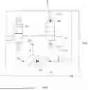
Turning now to FIG. 1, schematically a pump 100 is illustrated having an inlet I, an outlet O, and controllable pilot pressure line C, and a pressure less sump at PO. The pilot pressure control line C controls the pump 100 between a maximum output at low pilot pressure and a minimum output at high pilot pressure. A safety pressure relieve valve R may be in fluid connection with a pressureless oil sump at PO, which functions as a collection chamber and returns lubricant from the safety pressure relieve valve and engine components to the collection chamber, e.g. to capture lubricant leakage in the pump.
Pilot pressure control line C typically converts the pilot pressure P4 into a desired output flow at P2 in output line O, resulting in a desired pressure p3 in the gallery which is typically inverse to the pilot pressure P4, that is, when a pilot pressure is low, the pump outlet pressure output is increased, so that the pilot flow increases until an equilibrium is attained.
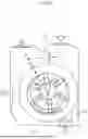
FIG. 2 and FIG. 3 show an exemplary embodiments of such a conventional pumps, in this case a vane pump having an inlet 8 (I in FIG. 3). FIG. 3 shows a further embodiment, wherein return line R is fluidly connected with an overpressure valve 201 (6 in FIG. 2). Typically, as a failsafe measure, the return line R fluidly connects to the pump outlet O via a first overpressure 201 valve for directing overpressure to the collection chamber to thereby spare the pump in case of overpressure. The overpressure valve 201 is capable of diverting lubricant pressure when the lubricant cannot flow out of the pump outlet O, (5 in FIG. 2) e.g. to the pressure gallery or engine components, e.g. due to clogging or a malfunction in the pump actuation.
FIG. 2 further shows a displaceable pump rotor 2 (R in FIG. 3), wherein the pump rotor eccentricity relative to the pump housing is controlled by pilot pressure control line C via a displacement actuator 202 that is controlled, preferably hydraulically, by the pilot pressure of control terminal C. The displacement actuator 202 is shown in more detail in FIG. 2 wherein the housing is formed by a stator 1 pivoting around a stator pivot point 4 and biased to a maximum eccentricity by a spring 7. This arrangement results in a pump stator 1 displacement that at minimum pilot pressure the pump has maximum eccentricity which maximizes flow through the rotating vanes V, which in the displayed embodiment adapt the vane heights in the eccentric rotation. However, when a pump pressure goes above its pressure limit, pilot pressure control in a pump control chamber (fluidly provided between the pilot pressure control terminal C and the actuator 202) may be too low to regulate the pump back to a reduced output, which may be caused by a pressure drop in the pressurized gallery between engine system and solenoid. This may result in pump 200 running at maximum eccentricity with extended vanes. Higher pressure in the pump 200 may cause higher bending stress on vanes V which may result in breakage of the rotor R and/or vanes V. A solution to this may include an overpressure valve 203 being provided between the pump outlet O and the pilot pressure control line C that in case of overpressure provides a lubricant flow from the pump outlet to the pilot pressure line additional to the pressurized lubricant flow from the regulating valve, to provide a maximum flow rate through the second overpressure valve that is higher than a pump leakage flow rate. Also cavitation could occur at higher eccentricities and pump speeds leading to oil pump failure.
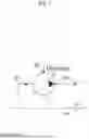
FIG. 4 shows a typical control scheme for regulating control pressure P4 in order to arrive at a desired gallery pressure P3 that services engine parts, schematically illustrated in the Figure. The rail gallery pressure P3 may be somewhat lower than the output pressure P2, due to pressure losses in the system, which will be discussed later in the disclosure.
To achieve a desired control pressure P4 a proportional solenoid valve is actuated, typically by pulse width modulation control to derive a controlled fraction of the gallery pressure P3 and input it to control terminal C as discussed in FIG. 1. Accordingly, a lubrication system 3000 is shown for an internal combustion engine 1000, comprising a pressure less lubricant collection chamber 50; a lubricant pump 100 having a pump inlet fluidly coupled to the collection chamber 50; and a pump outlet fluidly coupled to a lubricant filter module 60; said filter module 60 provided between the pump outlet and a lubricant gallery 70 being fluidly connected to selective engine parts 1000 to be lubricated. The lubricant pump 100 comprises a pilot pressure control line C; input line I and output line O. The pilot pressure line C is in fluid connection with the lubricant gallery 70 via a regulating valve 80, that controls a pressurized lubricant flow from the gallery 70 to the pilot pressure control line C.
During normal operating conditions the main gallery oil pressure p3 may be controlled closed loop with the proportional solenoid valve 80. The target (demand) p3 pressure is maintained by opening or closing the proportional solenoid valve from gallery to the regulating chamber of the oil pump 100, resulting in an oil flow and pressure p4 in the regulating chamber of the oil pump. A higher flow rate to the regulating chamber of the oil pump 100 will reduce the eccentricity thus displacement of the oil pump. This will result in a lower oil pump flow and outlet pressure p2 and lower gallery pressure p3. In turn a lower flowrate from the gallery through the solenoid valve to the regulating chamber will increase the oil pump eccentricity and oil pump outlet flow resulting in a higher gallery pressure p3.
However, unintended actuation of the proportional solenoid valve 80 could result in up to full opening of the solenoid valve, which would increase the regulating flow and pressure to a maximum and thus reduce the eccentricity of the oil pump. This might lead to undesired low gallery oil pressure p3. Low gallery pressure levels can be harmful for the engine, for which the invention proposes a control device, in case of malfunction of the proportional solenoid valve in such a way that the gallery pressure is actually lower than set by the closed loop control.
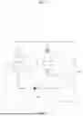
FIG. 5 shows a control scheme where this problem is addressed. The oil pressures are marked as oil sump pressure p0, oil pump inlet pressure p1, oil pump outlet pressure p2, gallery oil pressure p3, oil pump regulating chamber pressure p4 and pressure valve setting Pset. A control valve 90 is provided with a bias member 95 and is controlled by a terminal pressure 91 derived from the lubricant gallery 70 against a bias force provided by the bias member 95. In case of under pressure of the lubricant gallery 70 the bias member 95 actuates the control valve 90 to return to its normally open condition; thereby allowing fluid flow between the pilot pressure line C and the collection chamber 50 via a return line R to increase the pumps outlet pressure O until a minimum set pressure is reached in the lubricant gallery 70 in accordance with the bias force provided by the bias member 95; in which case the control valve 90 is kept in closed condition so that the pilot pressure C can regulate the lubricant pump 100. In this way a minimum set pressure of the gallery pressure p3 is provided by control valve 95 using a gallery pressure P4 as a pilot pressure to the control valve 95 that is normally open, against a bias force of a preset bias force Pset of a bias member, which may be a settable spring. In a too low pressure p3 i.e. p3<Pset of the gallery 70 the spring force will push the control valve 90 in its normally open position, draining the control pressure P4 and release it to the collection chamber 50 and thus forcing the pump to its maximum excentricity-thereby restoring the gallery pressure to its desired pressure defined by Pset. This prevents further lowering of gallery pressure and ensures safety despite proportional valve failure. As long as the control loop for the proportional solenoid fails, at least a minimum pressure is provided controlled by Pset. This condition can be summarized as follows:
-
- Control valve is opened as p3<pset
- Proportional solenoid valve is fully opened (failure)
- p4≈p0
- Oil pump not regulating (safe)
At the same time, as long as the gallery pressure p3 is above the minimum set pressure valve setting pset the control valve will not interfere with the normal regulating of lubricant pump 100. This condition can be summarized as follows:
-
- Control valve is closed as p3>pset
- Proportional valve is opened
- p3≥p4>p0
- Oil pump is regulating
The invention accordingly provides an additional pressure valve opening the oil pump regulating chamber to the oil sump and releasing its pressure p4 in case the gallery oil pressure p3 is below its predefined pressure valve setting Pset. Control valve is usually of a passive type in particularly mechanically regulated, but this is not mandatory.
FIG. 6 shows a schematic setup of a lubricant system 3000 according to an embodiment of the invention. A pump 101 is provided with a control valve Y2, in addition to a safety relief valve in return section R which fluidly connects the pump outlet O to the collection chamber S. Lubricant is supplied from the collection chamber S to pump inlet I and pumped out of outlet O. Filter module M conditions and filters the oil which may result in a pressure drop at reference numeral 4, relative to pump output pressure X at reference numeral 3.
The control valve at Y1 is provided between the pressure line C and collection chamber S via control pressure derived from gallery pressure from lubricant gallery G at Y1. The control valve Y2, when opened, lowers drains pilot pressure T1 in control chamber C in comparison with the pilot pressure provided by the solenoid valve SV that may be too high. Regulating valve SV may be a pulse width modulated controlled solenoid, that transfers a portion of the gallery pressure at reference numeral 5 to the pilot pressure control line C, dependent on a pressure drop Z of the pump due to leakage. Lubricant gallery G comprises a manifold fluidly connected to selective engine parts EP to be lubricated, such as bearings, valve trains, piston cooling jets and turbo-charger. Control valve and solenoid valve may be integrated in a single valve device. The control valve may also be integrated in the lubricant pump, for example in combination with the first and/or second overpressure valves discussed in FIG. 2.
The lubrication system accordingly provides a fail-safe functionality wherein during unintended actuation of the proportional solenoid valve, the regulating chamber pressure (p4) may rise, reducing pump displacement and gallery pressure (p3). To counteract this, the control valve activates, ensuring the system maintains a minimum gallery pressure (pset) to prevent engine damage. The fail safe functionality may be integrated in a single valve device: The control valve and solenoid valve may be integrated into a compact unit, reducing complexity and improving reliability. The functionality enhances flow limitation by supporting the integration of maximum and minimum flow limitation principles within the valve design. Its benefits comprise ensuring a minimum oil pressure under all conditions, protecting critical engine components; enhancing reliability by addressing underpressure and/or overpressure scenarios; and integrating into existing systems without performance trade-offs.
Claims
1: A lubrication system for an internal combustion engine, comprising a pressure less lubricant collection chamber; a lubricant pump having a pump inlet fluidly coupled to the collection chamber; and a pump outlet fluidly coupled to a lubricant gallery being fluidly connected to selective engine parts to be lubricated;
wherein said lubricant pump further comprises a pilot pressure control line; said pilot pressure control line controlling the pump between a maximum output at low pilot pressure and a minimum output at high pilot pressure;
said pilot pressure line in fluid connection with the lubricant gallery via a regulating valve, that controls a pressurized lubricant flow from the gallery to the pilot pressure control line;
wherein a control valve is provided with a bias member, said control valve controlled by a terminal pressure derived from the lubricant gallery against a bias force provided by the bias member, so that in case of under pressure of the lubricant gallery the bias member actuates the control valve to return to its normally open condition; thereby allowing fluid flow between the pilot pressure line and the collection chamber to increase the pumps output until a minimum set pressure is reached in the lubricant gallery in accordance with the bias force provided by the bias member; in which case the control valve is kept in closed condition so that the pilot pressure can regulate the lubricant pump.
2: The lubrication system according to claim 1, said lubricant pump further comprising a safety pressure relieve valve and said safety valve in fluid connection with the collection chamber; said return line fluidly connecting the pump outlet via a first overpressure valve for directing overpressure to the collection chamber.
3: The lubrication system according to claim 1, wherein a second overpressure valve is provided between the pump outlet and the pilot pressure line that in case of overpressure provides a lubricant flow from the pump outlet to the pilot pressure line additional to the pressurized lubricant flow from the regulating valve, to provide a maximum flow rate through the second overpressure valve that is higher than a pump leakage flow rate.
4: The lubrication system according to claim 1, wherein the control valve is passive.
5: The lubrication system according to claim 1, wherein the lubricant pump is powered by the internal combustion engine.
6: The lubrication system according to claim 1, wherein the lubricant pump comprises a displaceable pump rotor, wherein the pump rotor displacement is controlled by the pilot pressure control line via a hydraulic displacement actuator.
Images & Drawings included:


Sources:
- United States Patent and Trademark Office - verify current appl. status at the USPTO↗
Similar patent applications:
- » 20140137834
LUBRICATION SYSTEM, INTERNAL COMBUSTION ENGINE AND METHOD FOR OPERATING A LUBRICATION SYSTEM - » 20200182109
Internal combustion engine, lubrication system, and engine oil strainer - » 20130092118
Internal combustion engine with a lubrication system and method for producing an internal combustion engine - » 10660577
Lubricating system for internal combustion engine - » 20120234286
Lubrication system for an internal combustion engine, and method for lubrication - » 20080308353
Lubrication System and Internal Combustion Engine Comprising Such a System - » 20100037839
Nozzle, lubrication system and internal combustion engine comprising such a nozzle or such a system - » 10662423
Lubricating system for internal combustion engine - » 20070119405
Lubricating system for internal combustion engine - » 20110303181
PRE-LUBRICATION SYSTEM FOR INTERNAL COMBUSTION ENGINES
Recent applications in this class:
- » 20250354505 2025-11-20
INTERNAL COMBUSTION ENGINE ARRANGED WITH THE CRANKSHAFT AT THE TOP AND CORRESPONDING CONTROL METHOD - » 20250243794 2025-07-31
METHOD AND APPARATUS FOR MITIGATING FUEL IN OIL - » 20250207518 2025-06-26
OIL PRESSURE CONTROL SYSTEM AND CONTROL METHOD THEREOF - » 20250059899 2025-02-20
Internal Combustion Engine Control Device and Internal Combustion Engine Control Method - » 20240229690 2024-07-11
Motor Fluid Transfer System and Method - » 20240133323 2024-04-25
Motor Fluid Transfer System and Method - » 20240117760 2024-04-11
Lubricant delivery system and method - » 20240077006 2024-03-07
Engine lubrication systems, lubrication fluid circulation systems, and methods for regulating fluid pressure - » 20230417163 2023-12-28
CDA OPERATION-INTERLOCKED OIL JET SYSTEM - » 20230296038 2023-09-21
Powertrain, vehicle, and motor cooling method