SUPPORT STRUCTURE FOR A HEATING MATRIX
US20260176996A1
2026-06-25
19/127,311
2023-11-16
Smart Summary: A support structure is designed to hold a heating matrix in place within an exhaust gas line. The heating matrix is made of a honeycomb material with many channels for gas to flow through. This structure keeps the matrix stable against the inner walls of the housing. It consists of a central ring and several struts that reach out to touch the housing's surface. All parts can be connected using a joining method to ensure everything stays securely in place. 🚀 TL;DR
Abstract:
A support structure for positioning a heating matrix in an exhaust gas line spatially delimited by a housing, wherein the heating matrix is formed by a honeycomb body which has a multiplicity of flow channels through which flow can pass in a main flow direction, wherein the heating matrix is supported with respect to the inner surface of the housing by the support structure and the matrix is fixed with respect to the support structure by a plurality of coupling elements. The support structure is of multipart design having at least one central annular element and a plurality of struts, which project in a radial direction from the annular element and extend to the inner surface of the housing, and all the components are optionally joined by a joining method.
Inventors:
- JAN HODGSON 157 🇩🇪 TROISDORF, Germany
- Alexander MÖSELER 2 🇩🇪 Neunkirchen-Seelscheid, Germany
Applicant:
Interested in similar patents?
Get notified when new applications in this technology area are published.
Classification:
F01N3/2066 » CPC main
Exhaust or silencing apparatus having means for purifying, rendering innocuous, or otherwise treating exhaust for rendering innocuous by thermal or catalytic conversion of noxious components of exhaust characterised by methods of operation; Control specially adapted for catalytic conversion ; Methods of operation or control of catalytic converters Selective catalytic reduction [SCR]
F01N3/2013 » CPC further
Exhaust or silencing apparatus having means for purifying, rendering innocuous, or otherwise treating exhaust for rendering innocuous by thermal or catalytic conversion of noxious components of exhaust characterised by methods of operation; Control specially adapted for catalytic conversion ; Methods of operation or control of catalytic converters; Periodically heating or cooling catalytic reactors, e.g. at cold starting or overheating using electric or magnetic heating means
F01N3/2026 » CPC further
Exhaust or silencing apparatus having means for purifying, rendering innocuous, or otherwise treating exhaust for rendering innocuous by thermal or catalytic conversion of noxious components of exhaust characterised by methods of operation; Control specially adapted for catalytic conversion ; Methods of operation or control of catalytic converters; Periodically heating or cooling catalytic reactors, e.g. at cold starting or overheating using electric or magnetic heating means directly electrifying the catalyst substrate, i.e. heating the electrically conductive catalyst substrate by joule effect
F01N3/2828 » CPC further
Exhaust or silencing apparatus having means for purifying, rendering innocuous, or otherwise treating exhaust for rendering innocuous by thermal or catalytic conversion of noxious components of exhaust characterised by constructional aspects of converting apparatus; Construction of catalytic reactors characterised by structure, by material or by manufacturing of catalyst support; Ceramics Ceramic multi-channel monoliths, e.g. honeycombs
F01N3/2853 » CPC further
Exhaust or silencing apparatus having means for purifying, rendering innocuous, or otherwise treating exhaust for rendering innocuous by thermal or catalytic conversion of noxious components of exhaust characterised by constructional aspects of converting apparatus; Construction of catalytic reactors; Arrangements for mounting catalyst support in housing, e.g. with means for compensating thermal expansion or vibration using mats or gaskets between catalyst body and housing
F01N3/2864 » CPC further
Exhaust or silencing apparatus having means for purifying, rendering innocuous, or otherwise treating exhaust for rendering innocuous by thermal or catalytic conversion of noxious components of exhaust characterised by constructional aspects of converting apparatus; Construction of catalytic reactors; Arrangements for mounting catalyst support in housing, e.g. with means for compensating thermal expansion or vibration using mats or gaskets between catalyst body and housing the mats or gaskets comprising two or more insulation layers
F01N3/20 IPC
Exhaust or silencing apparatus having means for purifying, rendering innocuous, or otherwise treating exhaust for rendering innocuous by thermal or catalytic conversion of noxious components of exhaust characterised by methods of operation; Control specially adapted for catalytic conversion ; Methods of operation or control of catalytic converters
F01N3/28 IPC
Exhaust or silencing apparatus having means for purifying, rendering innocuous, or otherwise treating exhaust for rendering innocuous by thermal or catalytic conversion of noxious components of exhaust characterised by constructional aspects of converting apparatus Construction of catalytic reactors
Description
CROSS REFERENCE TO RELATED APPLICATIONS
This is a U.S. national stage of Application No. PCT/EP 2023/082089 filed Nov. 16, 2023. Priority is claimed on German Application No. DE 10 2022 212 259.3 filed Nov. 17, 2022, the contents of which are incorporated herein by reference.
BACKGROUND OF THE INVENTION
1. Field of the Invention
The disclosure relates to a support structure for positioning a heating matrix in an exhaust gas line spatially delimited by a housing, wherein the heating matrix is formed by a honeycomb body that has a multiplicity of flow channels through which flow can pass in a main flow direction, wherein the heating matrix is supported with respect to the inner surface of the housing by the support structure and the matrix is fixed with respect to the support structure by a plurality of coupling elements.
2. Description of the Related Art
Nowadays, electrical heating elements are often used to heat exhaust gases in an exhaust gas line downstream of an internal combustion engine, or the exhaust gas flowing in an exhaust gas line. The aim here is to more quickly reach a temperature threshold from which effective conversion of the pollutants entrained in the exhaust gas can take place. This is necessary because the catalytically active surfaces, used for exhaust gas aftertreatment, of the catalytic converters installed in the exhaust gas line only allow sufficient conversion of the respective pollutants from a minimum temperature, known as the light-off temperature.
The known solutions in the prior art include what are known as heated catalytic converters, which have a metallic structure connected to a voltage source or a metal-coated ceramic structure which can be heated up by exploiting ohmic resistance.
The heatable metallic structures can consist, for example, of a honeycomb body produced from metal foils. To do this, a plurality of smooth and/or at least partially structured metal foils are stacked one on top of another and are wound about at least one pivot point to form a honeycomb body. The matrix formed from the metal foils can be electrically contacted and be heated by exploiting ohmic resistance.
For this purpose, the matrix must be arranged in an exhaust gas line and situated upstream or downstream, in the direction of flow of the exhaust gas, of a catalytic converter designed for exhaust gas aftertreatment.
In order to position the matrix in the exhaust gas line and support it in particular with respect to mechanical and thermal loading which arises in particular with the high alternating thermal loading and also with the strong and uneven mechanical loading in an exhaust gas line, in particular the exhaust gas line of a motor vehicle, it is necessary to provide a mount.
The disadvantage of the known solutions in the prior art is, in particular, that the structures are of very complex construction and they are thus not optimal in terms of costs.
SUMMARY OF THE INVENTION
The problem to be solved by one aspect of the present invention is therefore that of providing a support structure for a heating matrix for spatially positioning the heating matrix in an exhaust gas line, which has a simplified construction and improved properties in respect of support relative to mechanical and thermal disturbances.
One exemplary aspect of the invention relates to a support structure for positioning a heating matrix in an exhaust gas line spatially delimited by a housing, wherein the heating matrix is formed by a honeycomb body that has a multiplicity of flow channels through which flow can pass in a main flow direction, wherein the heating matrix is supported with respect to the inner surface of the housing by the support structure and the matrix is fixed with respect to the support structure by a plurality of coupling elements, wherein the support structure is of multipart design, wherein the support structure has at least one central annular element and a plurality of struts, which project in a radial direction from the annular element and extend to the inner surface of the housing.
The support structure serves, in particular, for the permanent positioning of the heating matrix in the housing of the exhaust gas line. This must withstand the shocks and thermal loading and fix the heating matrix securely within the housing. Since the heating matrix is supplied with current during operation, and contact with the housing must be avoided to avoid short-circuiting or endangering persons, structural failure of the support structure must be excluded.
By a multipart construction of the support structure, it is possible to ensure that the different requirements on the strength of the support structure are met in an optimum manner. Thus, the attachment of the support structure to the inner surface of the housing must be designed to be particularly stable and rigid to ensure secure retention. However, the struts must have an increased elasticity with respect to the annular element in order to compensate for thermally induced stresses. In addition, the fastening points for the coupling elements must be arranged on the support structure in such a way that adequate tolerance compensation can be ensured during assembly.
These different requirements can be best met if the support structure is constructed from a plurality of components, which may have different material properties, in particular different coefficients of thermal expansion.
It is particularly advantageous if the annular element has at least one web, which interconnects two points of the annular element. By such a web, which passes through the center of the annular element or is at least close to the center, additional stabilization of the annular element can be achieved. In addition, such a web also offers the possibility of arranging coupling elements in the region of the center of the support structure without causing an excessive pressure loss for the exhaust gas flow.
It is also advantageous if the annular element is formed from a metal sheet that is punched or cut to size with a laser. One preferred exemplary aspect is characterized in that the struts are formed from a metal sheet that is punched or cut to size with a laser. By the abovementioned methods, it is possible to produce accurately fitting components in a particularly simple manner.
It is also to be preferred if the annular element and the struts are interconnected by a durable joining method from the group comprising laser welding, brazing, or welding. Particularly on account of the high thermal loading, the joining method selected should be one that allows secure durable joining under the given loading.
It is furthermore advantageous if the struts are formed from profiled metal sheets, wherein the struts have a higher section modulus in the axial direction, which corresponds to the main through-flow direction of the exhaust gas line, than in the radial direction. By profiled metal sheets it is possible to achieve direction-dependent strength of the components, enabling them to selectively have higher section moduli in one spatial direction and thus to be tailor-made for the intended use.
It is furthermore advantageous if the struts are of arc-shaped configuration and are arranged in a uniformly distributed manner in the circumferential direction of the housing. For reliable positioning of the annular element, a plurality of struts is required. To ensure uniform force distribution, it is therefore advantageous if the struts are arranged in a manner distributed at equal distances from one another in the circumferential direction of the housing.
It is also expedient if the support structure has a plurality of coupling elements, via which the matrix is secured on the support structure, wherein the coupling elements are arranged both on the struts and on the annular central element. The coupling elements serve to receive the heating matrix and are preferably configured in such a way that they can compensate for tolerances.
Advantageous developments of the present invention are described in the dependent claims and in the description of the figures that follows.
BRIEF DESCRIPTION OF THE DRAWINGS
The invention will be explained in detail below on the basis of an exemplary embodiment with reference to the drawing. In the drawing:
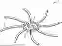
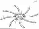
The FIGURE is a view of a support structure consisting of an annular element with a plurality of struts projecting in a radial direction.
DETAILED DESCRIPTION OF THE PRESENTLY PREFERRED EMBODIMENTS
The FIGURE shows a support structure 1 formed from a centrally arranged annular element 3 and a plurality of struts 2. The annular element 3 has an s-shaped web 4, which interconnects two points of the annular element 3.
The struts 2 project outward in a radial direction from the annular element 3 and are joined at their free end to a housing (not shown) or to another annular element (likewise not shown). In the example in the FIGURE, the struts 2 are arranged omnidistantly in the circumferential direction of the annular element 3 and are of arc-shaped design. In alternative embodiments, the distances in the circumferential direction may also be different. In addition, the struts 2 may also be of straight design or conform to some other shape. Moreover, additional connecting elements can be provided, the elements interconnecting the individual struts 2 for example. These can be arranged in a uniformly or nonuniformly distributed manner and can each interconnect two or more struts.
The exemplary embodiment of FIG. 1 is in particular not of a limiting nature and serves for illustrating the concept of the invention.
Thus, while there have shown and described and pointed out fundamental novel features of the invention as applied to a preferred embodiment thereof, it will be understood that various omissions and substitutions and changes in the form and details of the devices illustrated, and in their operation, may be made by those skilled in the art without departing from the spirit of the invention. For example, it is expressly intended that all combinations of those elements and/or method steps which perform substantially the same function in substantially the same way to achieve the same results are within the scope of the invention. Moreover, it should be recognized that structures and/or elements and/or method steps shown and/or described in connection with any disclosed form or embodiment of the invention may be incorporated in any other disclosed or described or suggested form or embodiment as a general matter of design choice. It is the intention, therefore, to be limited only as indicated by the scope of the claims appended hereto.
Claims
1.-8. (canceled)
9. A support structure configured to position a heating matrix in an exhaust gas line spatially delimited by a housing, wherein the heating matrix is formed by a honeycomb body which has a multiplicity of flow channels through which flow can pass in a main flow direction, wherein the heating matrix is supported with respect to an inner surface of the housing by the support structure and the matrix is fixed with respect to the support structure by a plurality of coupling elements, the support structure is of multipart design, comprising:
at least one central annular element; and
a plurality of struts, which project in a radial direction from the at least one annular element and extend to the inner surface of the housing.
10. The support structure as claimed in claim 9, wherein further comprising at least one web, which interconnects two points of the at least one annular element.
11. The support structure as claimed in claim 9, wherein the at least one annular element is formed from a metal sheet that is punched or cut to size with a laser.
12. The support structure as claimed in claim 9, wherein the plurality of struts are formed from a metal sheet that is punched or cut to size with a laser.
13. The support structure as claimed in claim 9, wherein the at least one annular element and the plurality of struts are interconnected by a durable joining method from the group consisting of laser welding, brazing, and welding.
14. The support structure as claimed in claim 9, wherein the plurality of struts are formed from profiled metal sheets, wherein the plurality of struts have a higher section modulus in an axial direction, which corresponds to a main through-flow direction of the exhaust gas line, than in a radial direction.
15. The support structure as claimed in claim 9, wherein the plurality of struts are of arc-shaped configuration and are arranged in a uniformly distributed manner in a circumferential direction of the housing.
16. The support structure as claimed in claim 9, wherein the support structure has a plurality of coupling elements, via which the matrix is secured on the support structure, wherein the coupling elements are arranged both on the plurality of struts and on the at least one annular central element.
Images & Drawings included:
Sources:
- United States Patent and Trademark Office - verify current appl. status at the USPTO↗
Similar patent applications:
- » 20260176995
SUPPORT STRUCTURE FOR A HEATING MATRIX
Recent applications in this class:
- » 20260153043 2026-06-04
MIXING PATH FOR AN EXHAUST GAS SYSTEM OF AN INTERNAL COMBUSTION ENGINE - » 20260146551 2026-05-28
HEATING ARRANGEMENT, AN EXHAUST TREATMENT SYSTEM COMPRISING THE HEATING ARRANGEMENT, A VEHICLE COMPRISING THE EXHAUST TREATMENT SYSTEM, AND A METHOD FOR A HEATING ARRANGEMENT - » 20260071565 2026-03-12
HOT SCR TEMPERING AIR SYSTEM FOR GAS TURBINE PART LOAD EFFICIENCY AND EXTENDED TURNDOWN - » 20260063060 2026-03-05
SYSTEMS AND METHODS FOR MANAGING AMMONIA SLIP IN AN AFTERTREATMENT SYSTEM - » 20260055718 2026-02-26
REDUCTANT DELIVERY SYSTEM, EXHAUST TREATMENT SYSTEM AND VEHICLE COMPRISING THE EXHAUST TREATMENT SYSTEM - » 20260055717 2026-02-26
REDUCTANT DELIVERY SYSTEM, EXHAUST TREATMENT SYSTEM AND VEHICLE COMPRISING THE EXHAUST TREATMENT SYSTEM - » 20260049565 2026-02-19
VEHICLE SYSTEM WITH INJECTION HOUSING AND TURBOCHARGER HAVING MOTOR - » 20260015958 2026-01-15
EXHAUST GAS AFTERTREATMENT SYSTEM IN AN EXHAUST GAS SYSTEM OF AN AMMONIA COMBUSTION ENGINE, METHOD AND USE THEREOF - » 20260002460 2026-01-01
FLUE GAS TREATMENT DEVICE AND DESIGN METHOD OF FLUE GAS TREATMENT DEVICE - » 20250376936 2025-12-11
DOSER MOUNT FOR EXHAUST AFTERTREATMENT SYSTEM