SELECTIVE RECIPROCATING ELEMENT DISABLEMENT IN A PUMP
US20260177053A1
2026-06-25
18/999,132
2024-12-23
Smart Summary: A pump system has parts that move back and forth to help move fluids. Each moving part can be connected to a push rod that makes it move. There are special retainers that can hold these moving parts in place so they don’t go backward when needed. The design allows for some moving parts to be disconnected from their push rods while others keep working. This means the pump can still operate even if some parts are not connected. 🚀 TL;DR
Abstract:
A pump system includes a fluid end with reciprocating elements configured to be reciprocated within respective bores in a body, with each reciprocating element including an engagement profile. The pump system also includes a power source operable to reciprocate push rods, each push rod releasably coupled to a respective reciprocating element. The pump system also includes retainers each independently operable to selectively engage the engagement profile of a respective reciprocating element to prevent the respective reciprocating element from traveling in a return direction. The pump system also includes connectors each releasably coupling respective push rods and reciprocating elements and configured to allow decoupling of a reciprocating element from a respective push rod. The power source is operable to continue to reciprocate reciprocating elements that remain coupled to push rods after at least one reciprocating element has decoupled from a respective push rod.
Inventors:
- Michael Foss 2 🇺🇸 Haslet, TX, United States
- Timothy Holiman Hunter 2 🇺🇸 Wichita Falls, TX, United States
Assignee:
- HALLIBURTON ENERGY SERVICES, INC. 10,800 🇺🇸 Houston, TX, United States
Applicant:
Interested in similar patents?
Get notified when new applications in this technology area are published.
Classification:
F04B53/147 » CPC main
Component parts, details or accessories not provided for in, or of interest apart from, groups - or - ; Pistons, piston-rods or piston-rod connections; Adaptation of piston-rods Mounting or detaching of piston rod
F04B9/02 » CPC further
Piston machines or pumps characterised by the driving or driven means to or from their working members the means being mechanical
F04B53/14 IPC
Component parts, details or accessories not provided for in, or of interest apart from, groups - or - Pistons, piston-rods or piston-rod connections
Description
BACKGROUND
Hydrocarbons, such as oil and gas, are commonly obtained from subterranean formations that may be located onshore or offshore. The development of subterranean operations and the processes involved in removing hydrocarbons from a subterranean formation are complex. Subterranean operations involve different steps such as, for example, drilling a wellbore at a desired well site, treating and stimulating the wellbore to optimize production of hydrocarbons, and performing the necessary steps to produce and process the hydrocarbons from the subterranean formation.
Drilling as well as treating and stimulating a wellbore can include, among other things, delivering various fluids (along with additives, proppants, gels, cement, etc.) to the wellbore under pressure and injecting those fluids into the wellbore. One example treatment and stimulation operation is a hydraulic fracturing operation in which the fluids are highly pressurized via pumping systems to create fractures in the subterranean formation. The pumping systems typically include crankshaft pumps, which are high-pressure, reciprocating pumps driven through conventional transmissions by diesel engines. These are used due to their ability to provide high torque to the pumps. Unfortunately, large maintenance costs are associated with the fluid ends and transmissions of such pumps used in stimulation operations.
Further, such pumps may include plungers or pistons that travel within the fluid ends to draw in and then displace the fluids into wellbore. The pumps may include, three, five, seven, or more such plungers. Should one plunger fail or need maintenance, the entire pump must be taken offline to service the pump, resulting in the loss of the entire pumping capacity of the pump.
BRIEF DESCRIPTION OF THE DRAWINGS
Aspects of the disclosure are described with reference to the following figures. The same or sequentially similar numbers are used throughout the figures to reference like features and components. The features depicted in the figures are not necessarily shown to scale. Certain features may be shown exaggerated in scale or in somewhat schematic form, and some details of elements may not be shown in the interest of clarity and conciseness.
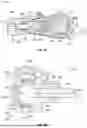
FIG. 1 is a diagram illustrating a system for wellbore treatment and stimulation operations, according to aspects of the present disclosure.
FIGS. 2A and 2B are cut-away illustrations of a power end and a cross-bore fluid end of a reciprocating pump, according to aspects of the present disclosure.
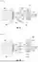
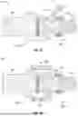
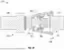
FIGS. 3A-3E are illustrations exemplary pump fluid ends with retainers and connectors, according to aspects of the present disclosure.
FIG. 4 is a diagram illustrating an example information handling system, according to aspects of the present disclosure.
DETAILED DESCRIPTION
The present disclosure describes embodiments of an improved reciprocating pump that includes a fluid end, in which reciprocating elements reciprocate via the operation of a power end to reciprocate respective push rods. The push rods are coupled to the reciprocating elements via releasable connectors. The pump also includes a retainer for each of the reciprocating elements. The retainers are independently operable to selectively engage an engagement profile of a respective reciprocating element to prevent the respective reciprocating element from traveling in a return direction toward the power end.
During operation, one or more of the reciprocating elements may experience performance degradation or failure while the remaining reciprocating elements are operating at normal or at least sufficient capacity. Overall, the number of reciprocating elements still sufficiently functioning may be able to provide sufficient capacity for the pump to justify continuing to operate the pump, albeit at a reduced capacity. An issue though is that the pump may not be able to continue to operate, even with reduced capacity, due to the degrading or failed reciprocating element. With the concepts of the present disclosure however, the degrading or failed reciprocating element(s) may be taken offline while the pump continues to operate using the rest of the reciprocating elements to continue to pump fluid. To do so, the reciprocating element(s) experiencing insufficient performance is identified. The respective retainer(s) for the identified reciprocating element(s) is then operated to move into engagement with the reciprocating element being taken offline. Once engaged, the retainer prevents the reciprocating element 318 from movement in the return direction. Also, the connector allows the decoupling of a reciprocating element from a respective push rod such that the pump can continue to operate and reciprocate all the push rods but without reciprocating the reciprocating elements to be taken offline. The decoupling of the reciprocating element(s) identified as inoperable allows the pump to continue to operate instead of having to take the entire pump offline.
FIG. 1 illustrates an example system 100 for well stimulation operations, according to aspects of the present disclosure. However, the pump systems described may also be used during well drilling or well treatment operations. The system 100 includes a fluid management system 102 in fluid communication with a blender system 104. The blender system 104 may in turn be in fluid communication with one or more pump systems 106 through a fluid manifold system 108. The fluid manifold system 108 may provide fluid communication between the pump systems 106 and a wellbore 110. In use, the fluid management system 102 may receive water or another fluid from a fluid source 112 (e.g., a ground water source, a pond, one or more frac tanks), mix one or more fluid additives into the received water or fluid to produce a treatment fluid with a desired fluid characteristic, and provide the produced treatment fluid to the blender system 104. The blender system 104 may receive the produced treatment fluid from the fluid management system 102 and mix the produced treatment fluid with a proppant, such as sand, or another granular material 114 to produce a final treatment fluid that is directed to the fluid manifold system 108. The pump systems 106 may then pressurize the final treatment fluid to generate pressurized final treatment fluid that is directed into the wellbore 110, where the pressurized final treatment fluid generates fractures within a formation in fluid communication with the wellbore 110.
The pump systems 106 may be any suitable pump systems for well operations. The disclosed pump systems 106 may each include at least three elongated cylindrical plunger bores 116 through which treatment fluid is pressurized via corresponding plungers 118. The plunger bores 116 are part of a fluid end 120 of the pump system 106, and the pump system 106 also includes a power end 122 for supplying motive force for the plungers 118 moving through the plunger bores 116 of the fluid end 120. As shown, the pump system 106 may be a triplex pump having three plunger bores 116. In other embodiments, the pump system 106 may be a quintuplex pump including five bores, a septuplex pump with seven bores, or a pump with even more bores. The power end 122 provides control of the position of the rods/plungers for suction, discharge, and pre-compression modes of operation. That is, the power end 122 is controllable to provide independent movement of the plunger 118 in the forward and return directions within the plunger bore 116. The plunger bores 116 are all fluidly connected to the same suction line 124 of the fluid manifold system 108. Although only one of the pump systems 106 of FIG. 1 is illustrated in detail to show these different parts of the decoupled long stroke pump system, it should be understood that the other pumps 106 of FIG. 1 may feature a similar structure.
The power end 122 of the pump systems 106 may include or be coupled to any desired type of drive system 126. In some embodiments, the drive system 126 may include one or more engines. Since the engines would be run at full speed and would be high on their torque curve, there will be no issues with having enough torque to come online under pressure. This allows the use of diesel engines, spark ignited engines, or turbine engines. The engines may receive energy or fuel in one or more forms from sources at the well site. The energy or fuel may include, for instance, hydrocarbon-based fuel, hydraulic energy, thermal energy, etc. The sources of energy or fuel may include, for instance, on-site fuel tanks, mobile fuel tanks delivered to the site, hydraulic pumping systems, etc. The engines may then convert the fuel or energy into mechanical energy that can be used to drive the associated pump system 106. For example, the engines may power pumps that provide hydraulic fluid to the power end 122 for actuating the plungers 118 of the pump system 106. In other embodiments, the drive system 126 may include an electric motor or an electric driven linear force actuator. The power end 122 of the pump system 106 may utilize any suitable power means for stroking the plungers 118: hydraulics, electric linear motors, roller screws, linear actuator mechanisms, or any other device providing linear power. Also, while the pump systems 106 are described as reciprocating pumps, the pump systems 106 may also include hydraulically driven intensifier pumps and double acting linear pumps with dual fluid ends.
As illustrated, the pump system 106 may include a skid or trailer 150 onto which all components of the pump system 106 are mounted. For example, the fluid end 120 and power end 122 are mounted on the skid or trailer 150. This arrangement may enable the pump system 106 to be assembled at a different location and transported to the well site in one piece. The skid or trailer 150 may include multiple separate skids/trailers that are transported individually to the well site and easily assembled there.
In one or more embodiments, the pump systems 106 may be communicatively coupled to a controller 152 that directs the operation of the power end 122 of the pump systems 106. The controller 152 may include, for instance, an information handling system that sends one or more control signals to the pump systems 106 to control the components of the drive system 126 and/or the power end 122. For example, in embodiments where the drive system 126 provides hydraulic force to the power end 122, the controller 152 may output control signals to the drive system 126 for controlling the amount of hydraulic force communicated. Additionally, or alternatively, the controller 152 may output control signals to various valves (not shown) within the power end 122 to control the mode of operation of the plunger bores 116.
As used herein, an information handling system may include any system containing a processor 154 and a memory device 156 coupled to the processor 154. The memory device 156 contains a set of instructions that, when executed by the processor 154, cause the processor 154 to perform certain functions. The control signals may take whatever form (e.g., electrical, hydraulic, pneumatic) is necessary to communicate with the associated drive system 126 and/or power end 122. For instance, a control signal to the drive system 126 may include a hydraulic or pneumatic control signal to one or more variable control valves, which may receive the control signal and alter the operation of the drive system 126 based on the control signal. In other embodiments, a control signal to the drive system 126 may include an electrical control signal to one or more electric linear motors, roller screws, or long stroke linear mechanisms, which may receive the control signal and alter the operation of the drive system 126 based on the control signal. Similarly, control signals in the form of hydraulic, pneumatic, or electrical control signals may be communicated to valves, linear actuators, or other components of the power end 122.
In one or more embodiments, the controller 152 may also be communicatively coupled to other elements of the system, including the fluid management system 102, the blender system 104, and the pump systems 106 to monitor and/or control the operation of the entire system 100. In other embodiments, some or all the functionality associated with the controller 152 may be located on the individual elements of the system, e.g., each of the pump systems 106 may have individual controllers that direct the operation of the associated drive systems 126 and/or power ends 122.
FIGS. 2A and 2B illustrate a pump 210 comprising a pump fluid end 222 and a pump power end 212. The pump fluid end 222 comprises a reciprocating element bore 224 in which a reciprocating element 218 can be reciprocated along a central axis 217 via the pump power end 212. The reciprocation is via coupling of the reciprocating element 218 to a pushrod 230, crank arm 220, and crankshaft 216 of the pump power end 212. A releasable connector 204 (discussed below) may be used to couple the reciprocating element 218 to the pump power end 212 (e.g., to the pushrod 230). Although not shown in FIGS. 2A and 2B, the pump 210 also includes a retainer operable to selectively engage the reciprocating element 218 to prevent movement of the reciprocating element 218 toward the power end 212. The retainer is discussed in more detail below with respect to FIGS. 3A-3E.
The pump 210 may comprise any suitable pump power end 212 for enabling the pump 210 to perform pumping operations (e.g., pumping a wellbore servicing fluid downhole). Similarly, the pump 210 may include any suitable housing 214 for containing and/or supporting the pump power end 212 and components thereof. The housing 214 may comprise various combinations of inlets, outlets, channels, and the like for circulating and/or transferring fluid. Additionally, the housing 214 may include connections to other components and/or systems, such as, but not limited to, pipes, tanks, drive mechanisms, etc. Furthermore, the housing 214 may be configured with cover plates or entryways for permitting access to the pump power end 212 and/or other pump components. As such, the pump 210 may be inspected to determine whether parts need to be repaired or replaced. The pump power end 212 may also be hydraulically or pneumatically driven, whether it is a non-intensifying or an intensifying system.
Those skilled in the art will understand that the pump power end 212 may include various components commonly employed in pumps. The pump power end 212 can be any suitable pump known in the art and with the help of this disclosure to be operable to reciprocate the reciprocating element 218 in the reciprocating element bore 224. For example, without limitation, the pump power end 212 can be operable via and comprise a crank and slider mechanism, a powered hydraulic/pneumatic/steam cylinder mechanism or various electric, mechanical, or electro-mechanical drives. For example, the pump power end 212 may include a rotatable crankshaft 216 attached to at least one reciprocating element 218 (e.g., a plunger or piston) by way of a crank arm/connecting rod 220 and a pushrod 230. Additionally, an engine (e.g., a diesel engine), motor (e.g., electric motor), or other suitable power source (not shown) may be operatively connected to the crankshaft 216 (e.g., through a transmission and drive shaft) and operable to actuate rotation thereof. In operation, rotation of the crankshaft 216 induces translational movement of the crank arm/connecting rod 220, thereby causing the pushrod 230 and thus the reciprocating element 218 to extend and retract along a path, which may generally be defined by the central axis 217 within the reciprocating element bore 224 (sometimes referred to herein for brevity as a “reciprocating element bore 224” or simply a “bore 224”, although not wishing to be limited to a particular reciprocating element 18). The pump 210 is typically mounted on a movable structure such as a semi-tractor trailer or skid, and the moveable structure may contain additional components, such as a motor or engine (e.g., a diesel engine), that provides power (e.g., mechanical motion) to the pump power end 212.
The pump fluid end 222 includes a fluid end body 208 and may be integrated with the pump power end 212 via an integration section 211 positioned in a space between the pump fluid end 22 and the pump power end 12 and safeguarded (e.g., from personnel) via a cover 215. The reciprocating element bore 224 is at least partially defined by a cylinder wall 226. As described further hereinbelow with reference to FIGS. 2A and 2B, the pump fluid end 222 can be a cross-bore pump fluid end 222 or, alternatively, an in-line or “concentric” bore pump fluid end. As utilized herein, cross-bore pump fluid ends can comprise “T-bore” pump fluid ends, “X-bore” (e.g., cross shaped bore) pump fluid ends, or “Y-bore” pump fluid ends. As discussed further below, the pump 210 includes at least one fluid inlet 238 for receiving fluid from a fluid source, e.g., a suction line, suction header, storage or mix tank, blender, discharge from a boost pump such as a centrifugal pump, etc. The pump 210 also includes at least one discharge outlet 254 for discharging fluid to a discharge source, e.g., a flowmeter, pressure monitoring and control system, distribution header, discharge line, wellhead, discharge manifold pipe, and the like.
In embodiments, the reciprocating element 218 comprises a plunger or a piston. While the reciprocating element 218 may be described herein with respect to embodiments comprising a plunger, it is to be understood that the reciprocating element 218 may comprise any suitable component for displacing fluid. In a non-limiting example, the reciprocating element 218 may be a piston. As those skilled in the art will readily appreciate, a piston-type pump generally employs sealing elements (e.g., rings, packing, etc.) attached to the piston and movable therewith. In contrast, a plunger-type pump generally employs fixed or static seals (e.g., primary seal or packing 229) through which the plunger moves during each stroke (e.g., suction stroke or discharge stroke).
While this discussion focuses on a pump fluid end 222 comprising a single reciprocating element 218 disposed in a single reciprocating element bore 224, it is to be understood that the pump fluid end 222 includes multiple reciprocating elements 218 and associated reciprocating element bores 224. In such a multi-bore pump, each reciprocating element bore 224 may be associated with a respective reciprocating element 218 and a crank arm 220, and a single common crankshaft 216 may drive each of the plurality of reciprocating elements 218 and crank arms 220. Alternatively, a multi-bore pump may include multiple crankshafts 216, such that each crankshaft 216 may drive a corresponding reciprocating element 218. Furthermore, the pump 210 may be implemented as any suitable type of multi-bore pump. In a non-limiting example, the pump 210 may comprise a triplex pump having three reciprocating elements 218 (e.g., plungers or pistons) and associated reciprocating element bores 224, discharge valve assemblies 272 (discussed below) and suction valve assemblies 256 (discussed below). The pump 210 may also include any number of additional reciprocating elements, such as a quintuplex pump having five reciprocating elements 218 and five associated reciprocating element bores 224, discharge valve assemblies 272 and suction valve assemblies 256. The pump 210 may even have, for example, seven or nine reciprocating elements 218.
As appreciated by those skilled in the art, the reciprocating element 218 may include any suitable size and/or shape for extending and retracting along a path within the pump fluid end 222. For instance, reciprocating element 218 may comprise a generally cylindrical shape, and may be sized such that the reciprocating element 218 can sufficiently slide against or otherwise interact with the inner cylinder wall 226. The pump fluid end 222 may include any other suitable component(s) and/or structure(s) for containing and/or supporting the reciprocating element 218 and providing the cylinder wall 226 at least partially defining the reciprocating element bore 224 along which the pump power end 212 can reciprocate the reciprocating element 218 during operation of the pump 210.
The reciprocating element bore 224 can have an inner diameter slightly greater than the outer diameter of the reciprocating element 218, such that the reciprocating element 218 may sufficiently reciprocate within reciprocating element bore 224. In embodiments, the fluid end body 208 of the pump fluid end 222 may have a pressure rating ranging from about 100 psi to about 3000 psi, or from about 2000 psi to about 10,000 psi, from about 5000 psi to about 30,000 psi, or from about 3000 psi to about 50,000 psi or greater. The fluid end body 208 of pump fluid end 222 may be cast, forged or formed from any suitable materials, e.g., steel, metal alloys, or the like. Those skilled in the art will recognize that the type and condition of material(s) suitable for the fluid end body 208 may be selected based on various factors. In a wellbore servicing operation, for example, the selection of a material may depend on flow rates, pressure rates, wellbore service fluid types (e.g., particulate type and/or concentration present in particle laden fluids such as fracturing fluids or drilling fluids, or fluids comprising cryogenic/foams), etc. Moreover, the fluid end body 208 (e.g., cylinder wall 226 defining at least a portion of reciprocating element bore 224 and/or pump chamber 228) may include protective coatings for preventing and/or resisting abrasion, erosion, and/or corrosion.
In embodiments, the cylindrical shape (e.g., providing cylindrical wall(s) 226) of the fluid end body 208 may be pre-stressed in an initial compression. Moreover, a high-pressure bore(s) providing the cylindrical shape (e.g., providing cylindrical wall(s) 226) may comprise one or more sleeves (e.g., heat-shrinkable sleeves). Additionally, or alternatively, the high-pressure bore(s) may comprise one or more composite overwraps and/or concentric sleeves (“over-sleeves”), such that an outer wrap/sleeve pre-loads an inner wrap/sleeve. The overwraps and/or over-sleeves may be non-metallic (e.g., fiber windings) and/or constructed from relatively lightweight materials. Overwraps and/or over-sleeves may be added to increase fatigue strength and overall reinforcement of the components.
The bores and bore-shaped components (e.g., providing cylindrical wall 226) associated with the pump fluid end body 208 of pump fluid end 222 may be held in place within the pump 210 using any appropriate technique. For example, components may be assembled and connected, e.g., bolted, welded, etc. Additionally, or alternatively, the bores may be in components that may be press-fit into openings machined or cast into the pump fluid end 222 or other suitable portion of the pump 210. Such openings may be configured to accept and rigidly hold the bores (e.g., having cylinder wall(s) 226 at least partially defining reciprocating element bore 224) in place to facilitate interaction of the reciprocating element 18 and other components associated with the pump 210.
The bore 224 may be in fluid communication with a discharge chamber 253 formed within the pump fluid end 222. Such a discharge chamber 253, for example, may be configured as a pressurized discharge chamber 253 having a discharge outlet 254 through which fluid is discharged by the reciprocating element 218. Thus, the reciprocating element 218 may be movably disposed within the reciprocating element bore 224, which may provide a fluid flow path into and/or out of the pump chamber. During operation of the pump 210, the reciprocating element 218 may be configured to reciprocate along a path (e.g., along central axis 217 within the bore 224 and/or a pump chamber 228) to transfer a supply of fluid to the pump chamber 228 and/or discharge fluid from the pump chamber 228. The pump fluid end 222 also comprises at least one valve assembly for controlling the receipt and output of fluid. For example, the pump fluid end 222 can comprise a suction valve assembly 256 and a discharge valve assembly 272 associated with each reciprocating element 218.
With FIG. 2B showing a cross-bore pump fluid end 222 engaged with a reciprocating element 218, the cross-bore pump fluid end 222 comprises the cross-bore fluid end body 208, a cross-bore pump chamber 228, a suction valve assembly 256, and a discharge valve assembly 272. In this cross-bore configuration, the suction valve assembly 256 and discharge valve assembly 272 are in a bore or channel 225 (also referred to herein as a cross bore 225) of the pump chamber 228, wherein the bore 225 has a central axis 227 that is perpendicular to the bore 224. The pump 210 may also comprise one or more access ports. For example, with reference to the cross-bore fluid end body 208 embodiment of FIG. 2B, a front access port 231A can be located on a front of the pump fluid end 222. A top or side access port 231B can be located on a top of the pump fluid end 222 and on a side (e.g., top side) of the discharge valve assembly 272 opposite suction valve assembly 256.
In embodiments, one or more seals 229 (e.g., “o-ring” seals, packing seals, or the like), also referred to herein as “primary” reciprocating element packing 229 may be arranged around the reciprocating element 218 to provide sealing between the outer walls of the reciprocating element 218 and the inner walls 226 defining at least a portion of the reciprocating element bore 224. Those skilled in the art will recognize that the seals may comprise any suitable type of seals, and the selection of seals may depend on various factors e.g., fluid, temperature, pressure, etc.
As noted above, the pump fluid end 222 comprises the suction valve assembly 256. The suction valve assembly 256 may alternately open or close to permit or prevent fluid flow. Those skilled in the art will understand that the suction valve assembly 256 may be of any suitable type or configuration (e.g., gravity- or spring-biased, flow activated, etc.). Those skilled in the art will also understand that the suction valve assembly 256 may be disposed within the pump fluid end 222 at any suitable location therein. For instance, the suction valve assembly 256 may be disposed within the bore 225 below the central axis 217 of the pump fluid end 222, in cross-bore pump fluid end 222 designs such as FIG. 2B, such that a suction valve body of the suction valve assembly 256 moves away from a suction valve seat within the a suction valve seat housing of reciprocating element 218 when the suction valve assembly 256 is in an open configuration and toward the suction valve seat when the suction valve assembly 256 is in a closed configuration.
The pump 210 also comprises the discharge valve assembly 272 for controlling the output of fluid through the discharge chamber 253 and the discharge outlet 254. Analogous to the suction valve assembly 256, the discharge valve assembly 272 may alternately open or close to permit or prevent fluid flow. Those skilled in the art will understand that the discharge valve assembly 272 may be disposed within the pump chamber at any suitable location therein. For instance, the discharge valve assembly 272 may be disposed within the bore 225 proximal the top of the pump fluid end 22, in cross-bore pump fluid end 222 designs such as FIG. 2B, such that a discharge valve body of the discharge valve assembly 272 moves toward the discharge chamber 253 when the discharge valve assembly 272 is in an open configuration and away from the discharge chamber 253 when the discharge valve assembly 272 is in a closed configuration. In addition, the discharge valve assembly 272 may be along the central axis 227 of the bore 225 perpendicular to central axis 217 in cross-bore pump fluid end 222 configurations such as FIG. 2B.
Further, the suction valve assembly 256 and the discharge valve assembly 272 can comprise any suitable mechanism for opening and closing valves. For example, the suction valve assembly 256 and the discharge valve assembly 272 can comprise a suction valve spring and a discharge valve spring, respectively. Additionally, any suitable structure (e.g., valve assembly comprising sealing rings, stems, poppets, etc.) and/or components may be employed suitable means for retaining the components of the suction valve assembly 256 and the components of the discharge valve assembly 72 within the pump fluid end 222 may be employed.
The fluid inlet 238 may be arranged within any suitable portion of the pump fluid end 222 and configured to supply fluid to the pump in any direction and/or angle. Moreover, the pump fluid end 222 may comprise and/or be coupled to any suitable conduit (e.g., pipe, tubing, or the like) through which a fluid source may supply fluid to the fluid inlet 238. The pump 210 may comprise and/or be coupled to any suitable fluid source for supplying fluid to the pump via the fluid inlet 238. In embodiments, the pump 210 may also comprise and/or be coupled to a pressure source such as a boost pump (e.g., a suction boost pump) fluidly connected to the pump 210 (e.g., via the inlet 238) and operable to increase or “boost” the pressure of fluid introduced to the pump 210 via the fluid inlet 238. A boost pump may comprise any suitable type including, but not limited to, a centrifugal pump, a gear pump, a screw pump, a roller pump, a scroll pump, a piston/plunger pump, or any combination thereof. For instance, the pump 210 may comprise and/or be coupled to a boost pump known to operate efficiently in high-volume operations and/or may allow the pumping rate therefrom to be adjusted. Those skilled in the art will readily appreciate that the amount of added pressure may depend and/or vary based on factors such as operating conditions, application requirements, etc. In one aspect, the boost pump may have an outlet pressure greater than or equal to about 70 psi, about 80 psi, or about 110 psi, providing fluid to the suction side of the pump 210 at about said pressures. Additionally, or alternatively, the boost pump may have a flow rate of greater than or equal to about 80 BPM, about 70 BPM, and/or about 50 BPM.
The multiple reciprocating elements may receive a supply of fluid from any suitable fluid source, which may be configured to provide a constant fluid supply. Additionally, or alternatively, the pressure of supplied fluid may be increased by adding pressure (e.g., boost pressure) as described previously. In embodiments, the fluid inlet(s) 238 receive a supply of pressurized fluid comprising a pressure ranging from about 30 psi to about 300 psi.
In embodiments, the pump fluid end 222 may comprise an external manifold (e.g., a suction header) for feeding fluid to the multiple reciprocating assemblies via any suitable inlet(s). Additionally, or alternatively, the pump fluid end 222 may comprise separate conduits such as hoses fluidly connected to separate inlets for inputting fluid to each reciprocating assembly. Of course, numerous other variations may be similarly employed, and therefore, fall within the scope of the present disclosure. Additionally, or alternatively, the discharge outlets 254 may be fluidly connected to a common collection point such as a sump or distribution manifold, which may be configured to collect fluids flowing out of the fluid outlets 254, or another bore bank and/or one or more additional pumps.
In operation, the reciprocating element 218 extends and retracts along a path to alternate between providing forward strokes in a forward direction (also referred to as discharge strokes and correlating to movement in a positive direction along the central axis 217) and return strokes in a return direction (also referred to as suction strokes and correlating to movement in a negative direction along the central axis 217), respectively. During a forward stroke, the reciprocating element 218 extends away from the pump power end 212 and toward the pump fluid end 222 as indicated by arrow 280. Before the forward stoke begins, the reciprocating element 218 is in a fully retracted position (also referred to as bottom dead center (BDC) with reference to the crankshaft 216), in which case the suction valve assembly 256 can be in a closed configuration having allowed fluid to flow into the (e.g., high pressure) pump chamber 228. (As utilized herein, “high pressure” indicates possible subjection to high pressure during discharge.) When discharge valve assembly 272 is in a closed configuration (e.g., under the influence of a closing mechanism, such as a spring), the high pressure in a discharge pipe or manifold containing discharge outlet 254 prevents fluid flow into discharge chamber 253 and causes pressure in the pump chamber 228 to accumulate upon stroking of the reciprocating element 218. When the reciprocating element 218 begins the forward stroke, the pressure builds inside the pump chamber 228 and acts as an opening force that results in positioning of the discharge valve assembly 272 in an open configuration, while a closing force (e.g., via a closing mechanism, such as a spring and/or pressure increase inside pump chamber 228) urges the suction valve assembly 256 into a closed configuration. When utilized in connection with a valve assembly, “open” and “closed” refer, respectively, to a configuration in which fluid can flow through the valve assembly (e.g., can pass between a valve body and a valve seat thereof) and a configuration in which fluid cannot flow through the valve assembly (e.g., cannot pass between a valve body and a valve seat thereof). As the reciprocating element 218 extends forward, fluid within the pump chamber 228 is discharged through the discharge outlet 254.
During a return stroke, the reciprocating element 218 reciprocates or retracts away from the pump fluid end 222 and towards the pump power end 212 of the pump 210 as indicated by arrow 280. Before the return stroke begins, the reciprocating element 218 is in a fully extended position (also referred to as top dead center (TDC) with reference to the crankshaft 216), in which case the discharge valve assembly 272 can be in a closed configuration having allowed fluid to flow out of the pump chamber 228 and the suction valve assembly 256 is in a closed configuration. When the reciprocating element 218 begins and retracts towards the pump power end 212, the discharge valve assembly 272 assumes a closed configuration, while the suction valve assembly 256 opens. As the reciprocating element 218 moves away from the discharge valve assembly 272 during a return stroke, fluid flows through the suction valve assembly 256 and into the pump chamber 228.
The multiple reciprocating elements 218 can be angularly offset of phase-shifted to ensure that no two reciprocating elements are located at the same position along their respective stroke paths (i.e., the plungers are “out of phase”) to improve fluid intake for each reciprocating element 218. For example, the reciprocating elements may be angularly distributed to have a certain offset (e.g., 360 degrees divided by the number of reciprocating elements such as 120 degrees of separation in a triplex pump). This distribution minimizes undesirable effects that may result from multiple reciprocating elements of a single pump simultaneously producing pressure pulses and ensures the multiple reciprocating elements 218 receive fluid and/or a certain quantity of fluid at all times of operation. The position of a reciprocating element is generally based on the number of degrees a pump crankshaft (e.g., crankshaft 16) has rotated from a bottom dead center (BDC) position. The BDC position corresponds to the position of a fully retracted reciprocating element at zero velocity, e.g., just prior to a reciprocating element moving (i.e., in a direction indicated by arrow 282 in FIG. 2B) forward in its bore. A top dead center position corresponds to the position of a fully extended reciprocating element at zero velocity, e.g., just prior to a reciprocating element moving backward (i.e., in a direction indicated by arrow 280 in FIGS. 2A and 2B) in its bore. Accordingly, when one reciprocating element 218 is at its maximum forward stroke position, a second reciprocating element 218 will be 60 degrees through its discharge stroke from BDC, and a third reciprocating element 218 will be 120 degrees through its suction stroke from top dead center (TDC).
FIGS. 3A-3E are embodiments of a reciprocating pump 310 with components and operations similar to the reciprocating pumps 106 and 210 discussed above. Similar components are given similar reference numbers as above; e.g., the pump 310 is similar to the pump 210. Since already discussed and for conciseness, not all the discussions of the components or operations will be repeated. The pump 310 includes a fluid end housing 308, in which a reciprocating element 318 reciprocates via the operation of a power end (not shown) to reciprocate a push rod 330. The push rod 330 is coupled to the reciprocating element 318 via a connector 304 releasably coupling the push rod 330 and the reciprocating element 318. The pump 310 also includes a retainer 390 for each of the reciprocating elements 318. The retainers 390 are independently operable to selectively engage an engagement profile 319 of a respective reciprocating element 318 to prevent the respective reciprocating element 318 from traveling in the return direction as shown by the arrow 380.
During operation of the pump 310, one or more of the reciprocating elements 318 may experience performance degradation or failure while the remaining reciprocating elements 318 are operating at normal or at least sufficient capacity. Overall, the number of reciprocating elements 318 still sufficiently functioning may be able to provide sufficient capacity for the pump 310 to justify continuing to operate the pump 310 at a reduced capacity. An issue though is that the pump 310 may not be able to continue to operate, even with reduced capacity, due to the degrading or failed reciprocating element 318. With the concepts of the present disclosure however, the degrading or failed reciprocating element(s) 318 may be taken offline while the pump 310 continues to operate using the rest of the reciprocating elements 318 to continue to pump fluid. To do so, the reciprocating element(s) 318 experiencing insufficient performance is identified based on measured operating metrics of the pump 310 that indicate a current or are used by a model to predict a future sufficient degradation or failure of the reciprocating element(s) 318. The respective retainer(s) 390 for the identified reciprocating element(s) 318 is then operated to move into engagement with the reciprocating element 318 being taken offline. Once engaged, the retainer 390 prevents the reciprocating element 318 from movement in the return direction.
Also, the connector 304 allows the decoupling of a reciprocating element 318 from a respective push rod 330 such that the pump 310 can continue to operate and reciprocate all the push rods 330 but without reciprocating the reciprocating element 318 to be taken offline. The engagement profile 319 of each reciprocating element 318, the retainer 390, and the releasable connector 304 may be any suitable form for retaining the reciprocating element 318 and releasing the push rod 330.
An example pump 310 is shown in FIG. 3A, where the engagement profile 319 of each reciprocating element 318 includes external or internal teeth; e.g., ratchet teeth, along a portion of the reciprocating element 318. Correspondingly, the retainer 390 includes one or more arms or pawls rotationally connected to a stationary portion of the pump 310. For normal pump operation, the pawls are selectively held in place out of engagement with the reciprocating element 318 by any suitable means such as a spring, locking mechanism, actuator, or other device. The pawls are also rotatable about a pin or other suitable hinge by being gravity- or spring-biased or by an actuator (not shown) using hydraulic, mechanical, or electrical power to provide rotational force to the pawls. Upon identifying a reciprocating element 318 for decoupling, the pawls may be released or actuated into engagement with the engagement surface 319 of the reciprocating element 318 using gravity or spring force or using the actuator (not shown). The actuator may be remotely actuated using the controller 152 (FIG. 1) and may also be automatically controlled based on measured operating metrics of the pump 310 that indicate a current or are used by a model to predict a future sufficient degradation or failure of the reciprocating element 318. After completing a forward stroke, the push rod 330 exerts force on the reciprocating element 318 in the return direction. Doing so allows the push rod 330 to separate from the reciprocating element 318 by producing enough force to break or release the connector 304 from either the reciprocating element 318 or the push rod 330 due to the retainer 390 holding the reciprocating element 318 from movement in the return direction, thus decoupling the reciprocating element 318. Once decoupled, the reciprocating element 318 has been taken offline and the pump 310 may continue to operate by reciprocating all the push rods 330 but only reciprocating the reciprocating elements 318 that remain coupled to the respective push rods 330.
Another example pump 310 is shown in FIG. 3B, where the engagement profile 319 of each reciprocating element 318 includes an external groove in a portion of the reciprocating element 318. Correspondingly, the retainer 390 includes one or more arms movably connected to a stationary portion of the pump 310. The arms may be any suitable shape for engagement with the external groove. For normal pump operation, the arms are selectively held in place out of engagement with the reciprocating element 318 by any suitable means such as a spring, locking mechanism, actuator, or other device. The arms are also movable by being gravity- or spring-biased or by an actuator (not shown) using hydraulic, mechanical, or electrical power to provide motive force to the arms. Upon identifying a reciprocating element 318 for decoupling, the arms may be released or actuated into engagement with the engagement surface 319 of the reciprocating element 318 using gravity or spring force or using the actuator (not shown). The actuator may be remotely actuated and may also be automatically controlled. The connector 304 also includes a chemical pack 305 that, when activated, causes a chemical reaction that degrades the connector 304 enough to break or release the connector 304. The chemical pack 304 may be actuated by any suitable means, including remote actuation by electric signal. After completing a forward stroke, the push rod 330 exerts force on the reciprocating element 318 in the return direction. Doing so allows the push rod 330 to separate from the reciprocating element 318. Once decoupled, the reciprocating element 318 has been taken offline and the pump 310 may continue to operate by reciprocating all the push rods 330 but only reciprocating the reciprocating elements 318 that remain coupled to the respective push rods 330.
Another example pump 310 is shown in FIG. 3C, where the engagement profile 319 of each reciprocating element 318 includes an external shoulder in a portion of the reciprocating element 318. Correspondingly, the retainer 390 includes one or more arms movably connected to a stationary portion of the pump 310. The arms may be any suitable shape for engagement with the external shoulder. For normal pump operation, the arm is selectively held in place out of engagement with the reciprocating element 318 by any suitable means such as a spring, locking mechanism, actuator, or other device. The arm is also movable by being gravity- or spring-biased or by an actuator (not shown) using hydraulic, mechanical, or electrical power to provide motive force to the arm. Upon identifying a reciprocating element 318 for decoupling, the arm may be released or actuated into engagement with the engagement surface 319 of the reciprocating element 318 using gravity or spring force or using the actuator (not shown). The actuator may be remotely actuated and may also be automatically controlled. After completing a forward stroke, the push rod 330 exerts force on the reciprocating element 318 in the return direction. Doing so allows the push rod 330 to separate from the reciprocating element 318 by producing enough force to break or release the connector 304 due to the retainer 390 holding the reciprocating element 318 from movement in the return direction. Once decoupled, the reciprocating element 318 has been taken offline and the pump 310 may continue to operate by reciprocating all the push rods 330 but only reciprocating the reciprocating elements 318 that remain coupled to the respective push rods 330.
Another example pump 310 is shown in FIG. 3D, where the engagement profile 319 of each reciprocating element 318 includes an external shoulder in a portion of the reciprocating element 318. Correspondingly, the retainer 390 includes one or more arms rotatably connected to the fluid end 322 of the pump 310. The arms may be any suitable shape for engagement with the external shoulder. For normal pump operation, the arms are selectively held in place out of engagement with the reciprocating element 318 by any suitable means such as a spring, locking mechanism, actuator, or other device. The arms are also movable by being gravity- or spring-biased or by an actuator (not shown) using hydraulic, mechanical, or electrical power to provide motive force to the arm. Upon identifying a reciprocating element 318 for decoupling, the arms may be released or actuated into engagement with the engagement surface 319 of the reciprocating element 318 using gravity or spring force or using the actuator (not shown). The actuator may be remotely actuated and may also be automatically controlled. After completing a forward stroke, the push rod 330 exerts force on the reciprocating element 318 in the return direction. Doing so allows the push rod 330 to separate from the reciprocating element 318 by producing enough force to break or release the connector 304 due to the retainer 390 holding the reciprocating element 318 from movement in the return direction. Once decoupled, the reciprocating element 318 has been taken offline and the pump 310 may continue to operate by reciprocating all the push rods 330 but only reciprocating the reciprocating elements 318 that remain coupled to the respective push rods 330.
Another example pump 310 is shown in FIG. 3E, where the engagement profile 319 of each reciprocating element 318 includes an external shoulder in a portion of the reciprocating element 318. Correspondingly, the retainer 390 includes one or more arms rotatably connected to the power end 312 of the pump 310. The arms may be any suitable shape for engagement with the external shoulder. For normal pump operation, the arms are selectively held in place out of engagement with the reciprocating element 318 by any suitable means such as a spring, locking mechanism, actuator, or other device. The arms are also movable by being gravity- or spring-biased or by an actuator (not shown) using hydraulic, mechanical, or electrical power to provide motive force to the arm. Upon identifying a reciprocating element 318 for decoupling, the arms may be released or actuated into engagement with the engagement surface 319 of the reciprocating element 318 using gravity or spring force or using the actuator (not shown). The actuator may be remotely actuated and may also be automatically controlled. After completing a forward stroke, the push rod 330 exerts force on the reciprocating element 318 in the return direction. Doing so allows the push rod 330 to separate from the reciprocating element 318 by producing enough force to break or release the connector 304 due to the retainer 390 holding the reciprocating element 318 from movement in the return direction. Once decoupled, the reciprocating element 318 has been taken offline and the pump 310 may continue to operate by reciprocating all the push rods 330 but only reciprocating the reciprocating elements 318 that remain coupled to the respective push rods 330.
FIG. 4 is a diagram illustrating an example information handling system 400, according to aspects of the present disclosure. The controller 152 of FIG. 1 may take a form similar to the information handling system 400. A processor or central processing unit (CPU) 401 of the information handling system 400 is communicatively coupled to a memory controller hub or north bridge 402. The processor 401 may include, for example a microprocessor, microcontroller, digital signal processor (DSP), application specific integrated circuit (ASIC), or any other digital or analog circuitry configured to interpret and/or execute program instructions and/or process data. Processor 401 may be configured to interpret and/or execute program instructions or other data retrieved and stored in any memory such as memory 403 or hard drive 407. Program instructions or other data may constitute portions of a software or application for carrying out one or more methods described herein. Memory 403 may include read-only memory (ROM), random access memory (RAM), solid state memory, or disk-based memory. Each memory module may include any system, device or apparatus configured to retain program instructions and/or data for a period of time (for example, computer-readable non-transitory media). For example, instructions from a software program or an application may be retrieved and stored in memory 403 for execution by processor 401.
Modifications, additions, or omissions may be made to FIG. 4 without departing from the scope of the present disclosure. For example, FIG. 4 shows a particular configuration of components of information handling system 400. However, any suitable configurations of components may be used. For example, components of information handling system 400 may be implemented either as physical or logical components. Furthermore, in some embodiments, functionality associated with components of information handling system 400 may be implemented in special purpose circuits or components. In other embodiments, functionality associated with components of information handling system 400 may be implemented in configurable general-purpose circuit or components. For example, components of information handling system 400 may be implemented by configured computer program instructions.
Memory controller hub (MCH) 402 may include a memory controller for directing information to or from various system memory components within the information handling system 400, such as memory 403, storage element 406, and hard drive 407. The memory controller hub 402 may be coupled to memory 403 and a graphics processing unit 404. Memory controller hub 402 may also be coupled to an I/O controller hub (ICH) or south bridge 405. ICH 405 is coupled to storage elements of the information handling system 400, including a storage element 406, which may comprise a flash ROM that includes a basic input/output system (BIOS) of the computer system. I/O hub 405 is also coupled to the hard drive 407 of the information handling system 400. I/O hub 405 may also be coupled to a Super I/O chip 408, which is itself coupled to several of the I/O ports of the computer system, including keyboard 409 and mouse 410.
Examples of the above aspects include:
Example 1 is a pump system comprising a fluid end comprising reciprocating elements configured to be reciprocated within respective bores in a body by moving in a forward direction in a forward stroke and in a return direction in a return stroke, each reciprocating element comprising an engagement profile; a power source operable to reciprocate push rods, each push rod releasably coupled to a respective reciprocating element, wherein reciprocation of the push rods reciprocates the reciprocating elements within the bores; retainers each independently operable to selectively engage the engagement profile of a respective reciprocating element to prevent the respective reciprocating element from traveling in the return direction; connectors each releasably coupling respective push rods and reciprocating elements and configured to allow decoupling of a reciprocating element from a respective push rod; and wherein the power source is operable to continue to reciprocate reciprocating elements that remain coupled to push rods after at least one reciprocating element has decoupled from a respective push rod.
Example 2 includes the aspects of any preceding examples or combinations thereof and further includes the pump system wherein at least one retainer retaining a respective reciprocating element from traveling in the return direction and the operation of the power source to move the respective push rod in the return direction decouples the reciprocating element from the push rod.
Example 3 includes the aspects of any preceding examples or combinations thereof and further includes the pump system wherein at least one connector is configured to allow the decoupling of a reciprocating element from a respective push rod by activation of a chemical reaction that degrades the connector.
Example 4 includes the aspects of any preceding examples or combinations thereof and further includes the pump system wherein at least one connector is configured to allow the decoupling of a reciprocating element from a respective push rod by actuation of an actuator that releases the connector.
Example 5 includes the aspects of any preceding examples or combinations thereof and further includes the pump system wherein at least one of the retainers comprises a pawl and the engagement profile of the respective reciprocating element comprises teeth such that engagement of the teeth by the pawl retains the reciprocating element from movement in the return direction.
Example 6 includes the aspects of any preceding examples or combinations thereof and further includes the pump system wherein at least one of the retainers comprises an arm and the engagement profile of the respective reciprocating element comprises a groove such that engagement of the groove by the arm retains the reciprocating element from movement in the return direction.
Example 7 includes the aspects of any preceding examples or combinations thereof and further includes the pump system wherein at least one of the retainers comprises an arm and the engagement profile of the respective reciprocating element comprises a shoulder such that engagement of the shoulder by the arm retains the reciprocating element from movement in the return direction.
Example 8 includes the aspects of any preceding examples or combinations thereof and further includes the pump system wherein the retainers are each independently operable using a retainer actuator.
Example 9 is a method of operating a pump system comprising operating a power source to reciprocate reciprocating elements in respective bores in a body of a fluid end by reciprocating push rods coupled to respective reciprocating elements to move in a forward direction in a forward stroke and in a return direction in a return stroke; identifying at least one reciprocating element for decoupling from a respective push rod; retaining the identified reciprocating element from movement in the return direction by engaging a retainer with an engagement profile of the identified reciprocating element; selectively decoupling the identified reciprocating element from the respective push rod; and continuing to operate the power source to reciprocate the reciprocating elements that remain coupled to respective push rods.
Example 10 includes the aspects of any preceding examples or combinations thereof and further includes the method wherein selectively decoupling the identified reciprocating element from the respective push rod comprises retaining the reciprocating element from movement in the return direction and operating the power source to move the respective push rod in the return direction to decouple the respective reciprocating element and push rod.
Example 11 includes the aspects of any preceding examples or combinations thereof and further includes the method wherein selectively decoupling the identified reciprocating element from the respective push rod comprises activating a chemical reaction that degrades a connector coupling the respective reciprocating element and push rod.
Example 12 includes the aspects of any preceding examples or combinations thereof and further includes the method wherein selectively decoupling the identified reciprocating element from the respective push rod comprises actuating an actuator that releases a connector coupling the respective reciprocating element and push rod.
Example 13 includes the aspects of any preceding examples or combinations thereof and further includes the method wherein the retainer comprises a pawl and the engagement profile of the identified reciprocating element comprises teeth such that engagement of the teeth by the pawl retains the identified reciprocating element from movement in the return direction.
Example 14 includes the aspects of any preceding examples or combinations thereof and further includes the method wherein the retainer comprises an arm and the engagement profile of the respective reciprocating element comprises a groove such that engagement of the groove by the arm retains the reciprocating element from movement in the return direction.
Example 15 includes the aspects of any preceding examples or combinations thereof and further includes the method wherein the retainer comprises an arm and the engagement profile of the respective reciprocating element comprises a shoulder such that engagement of the shoulder by the arm retains the reciprocating element from movement in the return direction.
Example 16 is a fluid end for a pump system comprising a power source operable to reciprocate push rods, the fluid end comprising bores in a body; and reciprocating elements configured to be reciprocated within respective bores by being releasably coupled to respective push rods to move in a forward direction in a forward stroke and in a return direction in a return stroke, each reciprocating element comprising an engagement profile, wherein each reciprocating element is configured to be prevented from moving in the return direction and decoupled from a respective push rod independently of the other reciprocating elements.
Example 17 includes the aspects of any preceding examples or combinations thereof and further includes the fluid end wherein the prevention of a reciprocating element from moving in the return direction causes the decoupling from the respective push rod as the push rod moves in the return direction.
Example 18 includes the aspects of any preceding examples or combinations thereof and further includes the fluid end wherein at least one reciprocating element is selectively decoupled by activation of a chemical reaction that releases the coupling with the respective push rod.
Example 19 includes the aspects of any preceding examples or combinations thereof and further includes the fluid end wherein the engagement profile of at least one reciprocating element comprises teeth.
Example 20 includes the aspects of any preceding examples or combinations thereof and further includes the fluid end wherein the engagement profile of at least one reciprocating element comprises a shoulder.
Certain terms are used throughout the description and claims to refer to particular features or components. As one skilled in the art will appreciate, different persons may refer to the same feature or component by different names. This document does not intend to distinguish between components or features that differ in name but not function.
For the aspects and examples above, a non-transitory computer readable medium can comprise instructions stored thereon, which, when performed by a machine, cause the machine to perform operations, the operations comprising one or more features similar or identical to features of methods and techniques described above. The physical structures of such instructions may be operated on by one or more processors. A system to implement the described algorithm may also include an electronic apparatus and a communications unit. The system may also include a bus, where the bus provides electrical conductivity among the components of the system. The bus can include an address bus, a data bus, and a control bus, each independently configured. The bus can also use common conductive lines for providing one or more of address, data, or control, the use of which can be regulated by the one or more processors. The bus can be configured such that the components of the system can be distributed. The bus may also be arranged as part of a communication network allowing communication with control sites situated remotely from system.
In various aspects of the system, peripheral devices such as displays, additional storage memory, and/or other control devices that may operate in conjunction with the one or more processors and/or the memory modules. The peripheral devices can be arranged to operate in conjunction with display unit(s) with instructions stored in the memory module to implement the user interface to manage the display of information. Such a user interface can be operated in conjunction with the communications unit and the bus. Various components of the system can be integrated such that processing identical to or similar to the processing schemes discussed with respect to various aspects herein can be performed.
While descriptions herein may relate to “comprising” various components or steps, the descriptions can also “consist essentially of” or “consist of” the various components and steps.
Unless otherwise indicated, all numbers expressing quantities are to be understood as being modified in all instances by the term “about” or “approximately”. Accordingly, unless indicated to the contrary, the numerical parameters are approximations that may vary depending upon the desired properties of the present disclosure. As used herein, “about”, “approximately”, “substantially”, and “significantly” will be understood by persons of ordinary skill in the art and will vary to some extent on the context in which they are used. If there are uses of the term which are not clear to persons of ordinary skill in the art given the context in which it is used, “about” and “approximately” will mean plus or minus 10% of the particular term and “substantially” and “significantly” will mean plus or minus 5% of the particular term.
The aspects disclosed should not be interpreted, or otherwise used, as limiting the scope of the disclosure, including the claims. It is to be fully recognized that the different teachings of the aspects discussed may be employed separately or in any suitable combination to produce desired results. In addition, one skilled in the art will understand that the description has broad application, and the discussion of any aspect is meant only to be exemplary of that aspect, and not intended to suggest that the scope of the disclosure, including the claims, is limited to that aspect.
Claims
What is claimed is:1. A pump system comprising:
a fluid end comprising reciprocating elements configured to be reciprocated within respective bores in a body by moving in a forward direction in a forward stroke and in a return direction in a return stroke, each reciprocating element comprising an engagement profile;
a power source operable to reciprocate push rods, each push rod releasably coupled to a respective reciprocating element, wherein reciprocation of the push rods reciprocates the reciprocating elements within the bores;
retainers each independently operable to selectively engage the engagement profile of a respective reciprocating element to prevent the respective reciprocating element from traveling in the return direction;
connectors each releasably coupling respective push rods and reciprocating elements and configured to allow decoupling of a reciprocating element from a respective push rod; and
wherein the power source is operable to continue to reciprocate reciprocating elements that remain coupled to push rods after at least one reciprocating element has decoupled from a respective push rod.
2. The pump system of claim 1, wherein at least one retainer retaining a respective reciprocating element from traveling in the return direction and the operation of the power source to move the respective push rod in the return direction decouples the reciprocating element from the push rod.
3. The pump system of claim 1, wherein at least one connector is configured to allow the decoupling of a reciprocating element from a respective push rod by activation of a chemical reaction that degrades the connector.
4. The pump system of claim 1, wherein at least one connector is configured to allow the decoupling of a reciprocating element from a respective push rod by actuation of an actuator that releases the connector.
5. The pump system of claim 1, wherein at least one of the retainers comprises a pawl and the engagement profile of the respective reciprocating element comprises teeth such that engagement of the teeth by the pawl retains the reciprocating element from movement in the return direction.
6. The pump system of claim 1, wherein at least one of the retainers comprises an arm and the engagement profile of the respective reciprocating element comprises a groove such that engagement of the groove by the arm retains the reciprocating element from movement in the return direction.
7. The pump system of claim 1, wherein at least one of the retainers comprises an arm and the engagement profile of the respective reciprocating element comprises a shoulder such that engagement of the shoulder by the arm retains the reciprocating element from movement in the return direction.
8. The pump system of claim 1, wherein the retainers are each independently operable using a retainer actuator.
9. A method of operating a pump system comprising:
operating a power source to reciprocate reciprocating elements in respective bores in a body of a fluid end by reciprocating push rods coupled to respective reciprocating elements to move in a forward direction in a forward stroke and in a return direction in a return stroke;
identifying at least one reciprocating element for decoupling from a respective push rod;
retaining the identified reciprocating element from movement in the return direction by engaging a retainer with an engagement profile of the identified reciprocating element;
selectively decoupling the identified reciprocating element from the respective push rod; and
continuing to operate the power source to reciprocate the reciprocating elements that remain coupled to respective push rods.
10. The method of claim 9, wherein selectively decoupling the identified reciprocating element from the respective push rod comprises retaining the reciprocating element from movement in the return direction and operating the power source to move the respective push rod in the return direction to decouple the respective reciprocating element and push rod.
11. The method of claim 9, wherein selectively decoupling the identified reciprocating element from the respective push rod comprises activating a chemical reaction that degrades a connector coupling the respective reciprocating element and push rod.
12. The method of claim 9, wherein selectively decoupling the identified reciprocating element from the respective push rod comprises actuating an actuator that releases a connector coupling the respective reciprocating element and push rod.
13. The method of claim 9, wherein the retainer comprises a pawl and the engagement profile of the identified reciprocating element comprises teeth such that engagement of the teeth by the pawl retains the identified reciprocating element from movement in the return direction.
14. The method of claim 9, the retainer comprises an arm and the engagement profile of the respective reciprocating element comprises a groove such that engagement of the groove by the arm retains the reciprocating element from movement in the return direction.
15. The method of claim 9, wherein the retainer comprises an arm and the engagement profile of the respective reciprocating element comprises a shoulder such that engagement of the shoulder by the arm retains the reciprocating element from movement in the return direction.
16. A fluid end for a pump system comprising a power source operable to reciprocate push rods, the fluid end comprising:
bores in a body; and
reciprocating elements configured to be reciprocated within respective bores by being releasably coupled to respective push rods to move in a forward direction in a forward stroke and in a return direction in a return stroke, each reciprocating element comprising an engagement profile,
wherein each reciprocating element is configured to be prevented from moving in the return direction and decoupled from a respective push rod independently of the other reciprocating elements.
17. The fluid end of claim 16, wherein the prevention of a reciprocating element from moving in the return direction causes the decoupling from the respective push rod as the push rod moves in the return direction.
18. The fluid end of claim 16, wherein at least one reciprocating element is selectively decoupled by activation of a chemical reaction that releases the coupling with the respective push rod.
19. The fluid end of claim 16, wherein the engagement profile of at least one reciprocating element comprises teeth.
20. The fluid end of claim 16, wherein the engagement profile of at least one reciprocating element comprises a shoulder.
Images & Drawings included:


Sources:
- United States Patent and Trademark Office - verify current appl. status at the USPTO↗
Recent applications in this class:
- » 20250277487 2025-09-04
CONNECTING ROD ASSEMBLY FOR RECIPROCATING PUMP - » 20250012270 2025-01-09
DIRECT LOAD WRIST PIN - » 20240271615 2024-08-15
POWER END ROD ASSEMBLY - » 20230213032 2023-07-06
Crosshead bushing systems and methods - » 20190242377 2019-08-08
Piston head retaining system - » 20180135620 2018-05-17
Hydraulic artificial lift for driving downhole pumps - » 20170175734 2017-06-22
Bellows anti-rotation construction - » 20170097000 2017-04-06
PUMP ASSEMBLY - » 20160369792 2016-12-22
Connecting rod and crosshead assembly for enhancing the performance of a reciprocating pump - » 20160281707 2016-09-29
Crosshead-piston rod assembly for a reciprocating compressor
Recent applications for this Assignee:
- » 20260177054 2026-06-25
STATIONARY PLUNGER PACKING - » 20260176958 2026-06-25
DATA-DRIVEN CONSTRAINED MODEL FOR CORROSION INSPECTION TOOLS - » 20260176929 2026-06-25
SYSTEM AND METHOD FOR ANCHORING AND STROKING A DOWNHOLE MOTOR MILLING ASSEMBLY IN A FLOATING RIG ENVIRONMENT - » 20260168358 2026-06-18
Brush Tool for Well Plug and Abandonment Operations and Installation of Completion Products - » 20260168348 2026-06-18
REINFORCED SWELL PACKER FOR WELLBORES - » 20260167563 2026-06-18
METHOD TO ENHANCE POZZOLAN REACTIVITY UTILIZING ACID - » 20260160917 2026-06-11
NON-INVASIVE CHARACTERIZATION OF WELLS - » 20260160163 2026-06-11
MULTIPHYSICS FOR WHITE HYDROGEN PROSPECTING - » 20260160161 2026-06-11
3D VISUALIZATION USING REAL TIME DATA FOR WELL INTERVENTION OPERATIONS - » 20260160160 2026-06-11
MONITORING CEMENT INTEGRITY FOR HYDROGEN LEAKAGE