APPARATUS AND METHODS FOR BOOSTING EFFICIENCY ON RECUPERATIVE RADIANT TUBE SYSTEMS
US20260177239A1
2026-06-25
18/990,332
2024-12-20
Smart Summary: A recuperative radiant tube system helps improve heating efficiency by using a special setup. It has a burner leg that creates hot gases through combustion and an exhaust leg for those gases to exit. A heat exchanger, called a recuperator, captures heat from the exhaust gases and transfers it to the air needed for combustion. Additionally, a booster assembly with another heat exchanger further enhances this heat transfer, making the system even more efficient. Overall, this design allows for better use of energy in heating processes. 🚀 TL;DR
Abstract:
A recuperative radiant tube system includes a radiant tube combustion system having a burner leg and an exhaust leg and is configured to produce a stream of products of combustion (POC) through a combustion process. A recuperator assembly is coupled to the exhaust leg and includes a first heat exchanger to facilitate heat exchange between a combustion air stream and the stream of POC in a recirculation loop. A booster assembly is coupled to the recuperator assembly and includes a second heat exchanger to facilitate additional heat exchange between the stream of POC and the combustion air stream outside the recirculation loop.
Applicant:
Interested in similar patents?
Get notified when new applications in this technology area are published.
Classification:
F23L15/04 » CPC main
Heating of air supplied for combustion Arrangements of recuperators
F23C9/006 » CPC further
Combustion apparatus characterised by arrangements for returning combustion products or flue gases to the combustion chamber the recirculation taking place in the combustion chamber
F23C9/00 IPC
Combustion apparatus characterised by arrangements for returning combustion products or flue gases to the combustion chamber
Description
TECHNICAL FIELD
The present disclosure generally relates to apparatus and methods for boosting efficiency of recuperative radiant tube systems, and more specifically for plug-in style recuperative radiant tube systems.
BACKGROUND
Radiant tube combustion systems are commonly used in industrial applications to provide indirect heat to a process such as heating steel, aluminum, etc. The purpose of the radiant tube is to allow a protective atmosphere to surround the product being heated. Internal to the radiant tube, fuel and oxidant are combusted to heat the radiant tube. Most commonly natural gas is supplied as the fuel and ambient air is supplied as the oxidant.
Due to the high processing temperature for industrial heat treating processes (about 1500° F.-about 1800° F.), the products of combustion (POC) carry significant energy when they leave the radiant tube system. In order to recover this lost energy, heat exchangers (termed “recuperators” in industrial combustion systems) are placed into the exhaust stream to transfer heat to the incoming air (termed “oxidant” or “combustion air”), and in some cases to the fuel stream for very low calorific values fuels.
Bayonet style recuperators are commonly used in radiant tube systems, installed into the exhausting leg of the radiant tube. The design allows for incremental improvements in efficiency to be achieved with a compact configuration. However, these bayonet recuperators have several limitations and disadvantages given the current market demands for reduction in carbon emissions (i.e., higher efficiency) and lower NOx (i.e., nitric oxide and nitrogen dioxide) emissions from the tube combustion.
SUMMARY
An exemplary recuperative radiant tube system includes a radiant tube combustion system having a burner leg and an exhaust leg and is configured to produce a stream of products of combustion (POC) through a combustion process. A recuperator assembly is coupled to the exhaust leg and includes a first heat exchanger to facilitate heat exchange between a combustion air stream and the stream of POC in a recirculation loop. A booster assembly is coupled to the recuperator assembly and includes a second heat exchanger to facilitate additional heat exchange between the stream of POC and the combustion air stream outside the recirculation loop.
An exemplary method of improving a thermal efficiency of a recuperative radiant tube system includes producing a stream of products of combustion (POC) through a combustion process in a burner of a radiant tube. The method includes passing the stream of POC to an exhaust leg of the radiant tube, through a recuperator assembly and subsequently through a booster assembly coupled to the recuperator assembly. The method includes recirculating a portion of the stream of POC exiting the recuperator assembly at a first exit into the burner and flowing rest of the stream of POC exiting the booster assembly at a second exit. The method includes passing a stream of combustion air through the booster assembly and subsequently through the recuperator assembly, the stream of combustion air flows from a colder end to a hotter end. The method further includes reversing a flow direction of the stream of combustion air to flow from the hotter end to the colder end, exiting the recuperator assembly at a third exit, and recirculating it to the burner. The recuperator assembly includes a first heat exchanger to facilitate heat exchange between the stream of combustion air and the stream of POC in a recirculation loop, and the booster assembly includes a second heat exchanger to facilitate additional heat exchange between the stream of POC and the stream of combustion air outside the recirculation loop.
An exemplary booster assembly is configured to couple to recuperator assembly in a recuperative radiant tube system, the recuperator assembly having a cold end and a hot end. The booster assembly includes an outer casing couplable to an outer casing of the recuperator assembly on the cold end, wherein the outer casing includes an inlet and an exhaust. An outer tube is disposed within the outer casing including a first opening and a second opening, wherein a first passage is formed between the outer casing and the outer tube. The booter assembly further includes a displacement tube that is closed on at least one end and is disposed within the outer tube. A second passage is formed between the displacement tube and the outer tube, the inlet of the outer casing is in fluid communication with the second passage and the exhaust of the outer casing is in fluid communication with the first passage. The booster assembly is configured to pass a stream of combustion air from the inlet through the second passage into the cold end of the recuperator assembly and receive a least a portion of a stream of products of combustion (POC) from the recuperator assembly and pass it through the first passage and exit the booster assembly from the exhaust.
BRIEF DESCRIPTION OF DRAWINGS
The disclosure is better understood with reference to the following drawings and description. The elements in the figures are not necessarily to scale, emphasis instead being placed upon illustrating the principles of the disclosure. Moreover, in the figures, like-referenced numerals may designate to corresponding parts throughout the different views.
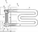
FIG. 1 is a schematic partial side sectional view of an exemplary recuperative radiant tube system.
FIG. 2 is a schematic partial side sectional view of a conventional recuperator illustrating conventional recuperator flow paths.
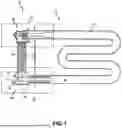
FIG. 3 is a schematic partial side sectional view of an exemplary recuperative radiant tube system disclosed herein illustrating recuperator flow paths with a booster added to the recuperator for efficiency improvement.
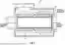
FIG. 4 is a perspective partial view of a symmetrical half of an exemplary recuperative radiant tube system of FIG. 3 having a radiant tube combustion system, a recuperator assembly coupled to an exhaust leg, and a booster assembly coupled to the recuperator assembly and is outside the POC recirculation loop.
FIG. 5 is an exploded perspective view of a symmetrical half of the recuperator assembly of the recuperative radiant tube system in FIG. 4.
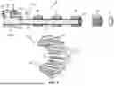
FIG. 6 is an exploded perspective view of a symmetrical half of the booster assembly of the recuperative radiant tube system in FIG. 4.
FIG. 7 is a schematic partial side sectional view of an exemplary booster assembly of FIG. 3 illustrating recuperator flow paths of counter flow heat exchange.
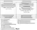
FIG. 8 shows an exemplary comparison of relative performances between balanced and unbalanced heat exchangers and issued associated with having an unbalanced heat exchanger.
In one or more implementations, not all of the depicted components in each figure may be required, and one or more implementations may include additional components not shown in a figure. Variations in the arrangement and type of the components may be made without departing from the scope of the subject disclosure. Additional components, different components, or fewer components may be utilized within the scope of the subject disclosure.
DETAILED DESCRIPTION
The detailed description set forth below is intended as a description of various implementations and is not intended to represent the only implementations in which the subject technology may be practiced. As those skilled in the art would realize, the described implementations may be modified in various different ways, all without departing from the scope of the present disclosure. Accordingly, the drawings and description are to be regarded as illustrative in nature and not restrictive.
FIG. 1 shows a schematic partial side sectional view of an exemplary recuperative radiant tube system 10. The exemplary recuperative radiant tube system 10 includes a radiant tube combustion system 12 that includes a radiant tube 14, a burner 16 positioned in a burner leg 18 of the radiant tube 14 and an exhaust 20 positioned in an exhaust leg 22 of the radiant tube 14. A stream of products of combustion (POC) 24 produced by the radiant tube combustion system 12 is passed to the exhaust leg 22. A recuperator assembly 26 is coupled to (e.g., plug in) the exhaust leg 22 of the radiant tube 14 to facilitate exchange between a combustion air stream 23 and a stream of POC 24. In the illustrated example, the combustion air stream 23 (e.g., ambient air) enters the recuperator assembly 26 at a combustion air inlet 27 and flows from a relatively cold end to a relatively hot end. The combustion air stream 23 is heated by heat transfer from the stream of POC 24 through tubes of the recuperator assembly 26. The flow direction of the combustion air stream 23 reverses at the hot end and flows in a reverse direction away from the hot end. The combustion air stream 23 is at a higher temperature (termed “preheated combustion air” 25) than when it enters due to the heat transfer from the stream of POC 24. This preheated combustion air 25 is circulated back to the burner 16 of the radiant tube 14. The stream of POC 24 transfers its heat to the combustion air stream 23; a portion of the stream of POC 24 is recirculated back to the burner 16 of the radiant tube 14 (termed “recirculated flue gases” or “recirculated POC” 29) and a portion of the stream of POC 24 exits the recuperative radiant tube system 10 at the exhaust 20.
FIG. 2 is a schematic partial side sectional view of a conventional recuperator illustrating conventional recuperator flow paths. In particular, FIG. 2 illustrates an exemplary configuration of the recuperator assembly 26 that is a bayonet style heat exchanger compatible with the radiant tube 14 in FIG. 1. In the illustrated example, the oxidant is an ambient air which enters on the centerline of the tube from the left side of FIG. 2. The combustion air travels left to right through the center tube of the recuperator absorbing heat liberated from the returning passage of preheated combustion. This preheated combustion air then flows from right to left in the annuls formed by the outside of the center tube and the inside of a heat exchanger section. Internal fins may be used to enhance the heat transfer surface area of the heat exchanger sections.
As the combustion air returns from right to left, heat is transferred from the hot products of combustion (POC) entering the annular area formed by the inside diameter of the radiant tube and the outside of the heat exchanger sections. These hot POC gases flow from right to left in FIG. 2. The outside diameter of the heat exchanger sections typically includes protruding fins for heat transfer enhancement. Given that both the annular combustion air and the POC flow travel from right to left on either side of the heat exchange section, this flow is defined as “parallel flow.” Likewise, since the combustion air first flows left to right in the center tube and right to left in the return annulus, the flow on both sides of the center tube is referred to as “counter-flow.” The preheated combustion air exits from the side of the recuperator and is directed over to a burner on the tube inlet. The above described heat exchange process reduces the temperature of the exhaust gases leaving the radiant tube system and increases the temperature of the combustion air.
While the process illustrated in FIG. 2 improves efficiency, combustion temperatures can also increase resulting in significant increases in NOx emissions, a regulated pollutant. To reduce these NOx emissions, a portion of the POC's flow is directed back to the combustion process. The recirculated flue gases dilute the combustion occurring from the burner, significantly reducing the NOx emissions. Additionally, this recirculated POC flow improves the surface temperature uniformity of the radiant tube, leading to improved life and overall heat transfer to the process. The rest of the POC flow leaves the radiant tube system control volume, exiting from the side of the recuperator.
Although the bayonet recuperator illustrated in FIG. 2 provides an effective means of heat recovery, the effectiveness is limited due to the heat exchanger design. As the entering and exiting combustion air pass on either side of the inner surface, the exit temperature is reduced by the incoming ambient air, limiting the maximum temperature and hence efficiency.
Another significant limitation for existing bayonet recuperators is in cases where high percentages of flue gases are recirculated as is the case for many contemporary systems. The issue is that heat exchanger performance is better optimized when the mass flow on the combustion air side matches the mass flow on the POC side. As the POC rate is significantly increased to 100% or in excess, the mass flow becomes imbalanced, e.g., about 2 times to three times of the combustion air flow. With these high recirculation rates, the exhaust temperatures increase significantly with a proportionate reduction in thermal efficiency.
The present disclosure is configured to improve or overcome the above-discussed limitations. Specifically, the present disclosure overcomes the limitations of the bayonet recuperators by adding a “booster” assembly to the entrance of the heat exchanger. The booster assembly disclosed herein utilizes a counter-flow design to optimize the temperature differences for maximum heat transfer and is located outside of the POC recirculation zone or loop resulting in balanced mass flows across the heat exchange surface.
FIG. 3 is a schematic partial side sectional view of an exemplary recuperative radiant tube system 60 disclosed herein illustrating recuperator flow paths with a booster added to the recuperator for efficiency improvement.
In a different view, FIG. 4 shows a perspective partial view of a symmetrical half of the recuperative radiant tube system 60 disclosed herein. A recuperator assembly 66 is coupled to an exhaust leg of a radiant tube 67. The recuperator assembly 66 includes an outer tube 68 having a closed end 70 and is disposed within the radiant tube 67. A first passage 72 is formed between an inner surface of the radiant tube 67 and the outer tube 68. An inner tube 74 disposed within the outer tube 68 and has a first opening 76 away from the closed end 70 of the outer tube 68 and a second opening 78 facing the closed end 70 of the outer tube 68. A second passage 80 is formed between the inner tube 74 and the outer tube 68. An outer casing 82 is coupled to the outer tube 68 and the radiant tube 67. The outer casing 82 at least partially encloses the inner tube 74 with a first outlet 84 in fluid communication with the first passage 72 and a second outlet 86 in fluid communication with the second passage 80.
A booster assembly 88 is coupled to the recuperator assembly 66 on the opposite side of the radiant tube 67. The booster assembly 88 includes an outer casing 90 coupled to the outer casing 82 of the recuperator assembly 66 and has an inlet 92 and an exhaust 94. An outer tube 96 disposed within the outer casing 90 and has a first opening 98 and a second opening 100. A third passage 102 is formed between the outer casing 90 and the outer tube 96. A displacement tube 104 closed on both ends or closed only on the end facing the inlet 92 is disposed within the outer tube 96. A fourth passage 106 is formed between the displacement tube 104 and the outer tube 96. The inlet 92 of the outer casing 90 is in fluid communication with the fourth passage 106 and the exhaust 94 of the outer casing 90 is in fluid communication with the third passage 102.
FIG. 5 shows an exploded perspective view of a symmetrical half of the recuperator assembly 66. The first passage 72 is formed between the inner surface of the radiant tube 54 and the outer tube 68, and the second passage 80 is formed between the inner tube 74 and the outer tube 68. As shown in an enlarged view 110, the outer tube 68 includes protruding fins 112 and 114 in both outer and inner surfaces. The protruding fins 112 and 114 may be any suitable sizes and shapes (e.g., fin, triangle, etc.) for heat transfer enhancement when contacting the flows through the first passage 72 and the second passage 80. The outer tube 68 may be assembled from a plurality of sections. In the illustrated example, the outer tube 68 includes three sections; however, the number of sections can be any suitable number, e.g., 1, 2, 3, 4, 5, 6 . . . , etc. A ring, nuts, and bolts 116 or any other suitable fastening/coupling mechanisms may be used to couple various components of the recuperator assembly 66.
In a different view, FIG. 6 shows an exploded perspective view of a symmetrical half of the booster assembly 88. The third passage 102 is formed between the outer casing 90 and the outer tube 96, and the fourth passage 106 is formed between the displacement tube 104 and the outer tube 96. As shown in an enlarged view 120, the outer tube 96 includes protruding fins 122 and 124 in both outer and inner surfaces. The protruding fins 122 and 124 may be any suitable sizes and shapes (e.g., fin, triangle, etc.) for heat transfer enhancement when contacting the flows through the third passage 102 and the fourth passage 106. The outer tube 96 may be assembled from a plurality of sections. In the illustrated example, the outer tube 96 includes two sections; however, the number of sections can be any suitable number, e.g., 1, 2, 3, 4, 5, 6 . . . , etc. A ring, nuts, and bolts 126 or any other suitable fastening/coupling mechanisms may be used to couple various components of the booster assembly 88. The displacement tube 104 has a closed end 105 facing the inlet 92, and other end 107 may be open or closed.
Referring back to FIG. 4, a stream of combustion air 130 and a stream of POC 132 are indicated by arrows flowing through the booster assembly 88 and the recuperator assembly 66. In the illustrated figure, from right to left, the stream of POC 132 flows from the radian tube 67, passes through the recuperator assembly 66, and through the booster assembly 88. In particular, the POC 132 flows through the first passage 72, and then a portion of the POC 132 exits the recuperator assembly 66 at the first outlet 84 and recirculates back to the burner (the burner 16) while the remaining portion of the POC 132 continues through the third passage 102 into the booster assembly 88 and exits the recuperative radiant tube system 60 at the exhaust 94.
In the illustrated figure, from left to right, the stream of combustion air 130 (e.g., ambient air) flows into the booster assembly 88 and flows through the recuperator assembly 66. The combustion air 130 then reverses its flow direction to flow from right to left, and exits the recuperator assembly 66 at the second outlet 86. In particular, the combustion air 130 flows through the annulus along the length of heat exchange sections (the fourth passage 106) until it is diverted into the center tube (the inner tube 74) of the bayonet heat exchanger (the recuperator assembly 66) and flows into the first opening 76 and out from the second opening 78. Once the combustion air 130 exits the second opening 78, it reverses its direction and flows into the second passage 80.
Due to the heat exchange, the POC 132 exiting the exhaust 94 and the POC 132 exiting the first outlet 84 are at lower temperatures. For example, the temperature reduction is about 35% to about 40% at the exhaust 94 and is about 20% to about 25% at the first outlet 84 as compared to the POC 132 temperature in the radiant tube 67 before flowing into the recuperator assembly 66. The POC 132 exiting the first outlet 84 recirculates back to the burner (the burner 16). This recirculated POC flow improves the surface temperature uniformity of the radiant tube leading to improved life, reduced NOx emissions, and overall heat transfer to the process.
Due to the heat exchange, the combustion air 130 is at a higher temperature (termed “preheated combustion air”) than when it enters the booster assembly 88. The increase in the combustion air 130 temperature is about 35% to about 45% as compared to the ambient air temperature before it flows into the booster assembly 88. This preheated combustion air 130 is circulated back to the burner (the burner 16) of the radiant tube 67 through the second outlet 86. This reheated combustion air an effective means of heat recovery.
Furthermore, it is worth mentioning that temperature profiles of counter-flow heat exchange result in higher heat transfer rates for the same surface area than parallel flow exchangers. That is counter-flow heat exchangers achieve much higher heat transfer rates than the bayonet heat exchangers of the same surface area. FIG. 7 shows a schematic partial side sectional view of the booster assembly 88 illustrating recuperator flow paths of counter flow heat exchange. By adding the booster assembly 88 outside the recirculation zone or loop, the heat exchange mode changes from bayonet style (e.g., heat exchange in the recuperator assembly 66) to counter-flow in a second heat exchange stage (e.g., heat exchange in the booster assembly 88). The counter-flow in the booster assembly 88 is formed between the POC 132 and the combustion air 130 flowing in the opposite directions. The POC 132 flows from the hotter side to the colder side through the third passage 102 (e.g., from right to left in FIG. 7) and the combustion air 130 flows from the colder side to the hotter side through the fourth passage 106 (e.g., from left to right in FIG. 7). This coupling of the second, counter-flow, design allows for much higher heat exchange efficiencies to be achieved.
In a conventional recuperator (without the booster assembly 88), the thermal efficiency suffers in instances where high POC recirculation rates are required. By adding the booster assembly 88 outside the recirculation zone or loop, the improvement in thermal efficiency increases with an increasing ratio of the recirculated POC:POC exhaust (e.g., a mass ratio of the POC exiting the first outlet 84:the POC exiting the exhaust 94). The improvement in thermal efficiency is the difference in thermal efficiencies of the configuration with the booster assembly 88 coupled to the recuperator assembly 66 and the recuperator assembly 66 alone without the booster assembly 88. By adding the booster assembly 88 outside the recirculation loop, the thermal efficiency is improved by about 10% to about 20% and the temperature of the exhaust gas (POC exhaust exiting at the exhaust 94) is reduced by about 10% to about 20% as compared to a recuperative radiant tube system without the booster assembly 88. Such improvements in efficiency become even more prominent when the recuperator system operates at a high recirculation rate. For example, for a conventional recuperative system (e.g., without the booster assembly 88), an overall radiant tube combustion efficiency of 60% is achievable under a standard operation. Adding 30% recirculation (e.g., the recirculated POC:POC exhaust=1.3:1) reduces the efficiency to about 50%, adding 100% recirculation (e.g., the recirculated POC:POC exhaust=2:1) reduces the efficiency to about 30%, and adding 150% recirculation (e.g., the recirculated POC:POC exhaust=2.5:1) reduces the efficiency to 24%. In contrast, the radiant tube recuperative system 60 with the booster assembly 88 is capable of achieving high efficiencies even at high circulation rates: combustion efficiency of 60% under a standard operation, 59% at 30% recirculation, 57% at 100% recirculation, and 55% at 150% recirculation. Since the booster assembly 88 is outside of the radiant tube control volume, it is minimally impacted by the recirculation rate. In cases of high recirculation, the size of the recuperator assembly 66 may be minimized if the booster assembly 88 was made larger.
As an example, the recuperative radiant tube system 60 may have a thermal efficiency that is improved by about 25% to about 35% as compared to a recuperative radiant tube system without the booster assembly 88 at a recirculated POC:POC exhaust of about 0.2:1.0. As another example, the recuperative radiant tube system 60 may have a thermal efficiency that is improved by about 50% to about 75% as compared to a recuperative radiant tube system without the booster assembly 88 at a recirculated POC:POC exhaust of about 1.5:1.0. As another example, the recuperative radiant tube system 60 is capable of recirculating the POC exiting the first outlet 84 back to the burner 16 at a recirculation rate that is 0.2 times the POC exiting the exhaust 94, and the thermal efficiency is improved by about 15% to about 25% as compared to a recuperative radiant tube system without the booster assembly 88 at the same recirculation rate. As another example, the recuperative radiant tube system 60 is capable of recirculating the POC exiting the first outlet 84 back to the burner 16 at a recirculation rate that is 1.5 times the POC exiting the exhaust 94, and the thermal efficiency is improved by about 150% to about 160% as compared to a recuperative radiant tube system without the booster assembly 88 at the same recirculation rate.
By adding the booster assembly 88 outside of the recirculation zone or loop, the resulting flow across the heat exchanger is closer to balance (e.g., closer to 1:1) with the POC mass flow approximately being about 1.2 to about 1.3 times the combustion air mass flow, as opposed to about 2 to about 3 times for a recirculated stream. The balanced mass flow increases the thermal efficiencies to higher values than what is attainable with an imbalanced heat exchanger. FIG. 8 shows an example comparison of relative performances between balanced and unbalanced heat exchangers and issues associated with having an unbalanced heat exchanger.
In operation, the booster assembly 88 enables a method of improving efficiency of a radiant tube combustion system. The method includes steps of producing a stream of products of combustion (POC) 132 through a combustion process and passing the stream of POC 132 to the exhaust leg, through the recuperator assembly 66 and through the booster assembly 88, from the hot end to the cold end. A portion of the stream of POC 132 exits the recuperator assembly 66 at a first exit (the first outlet 84), and rest of the stream of POC 132 exits the booster assembly 88 at a second exit (the exhaust 94). The steps include passing a stream of combustion air 130 through the booster assembly 88 and through the recuperator assembly 66, from the cold end to the hot end and heating the stream of combustion air 130 by heat transfer from the stream of POC 132 through surface area of the recuperator assembly 66 and surface area of the booster assembly 88. The steps include reversing the direct of the stream of combustion air 130 at the hot end and directing the stream of combustion air 130 in a reverse direction away from the hot end and exiting the recuperator assembly 66 at a third exit (the second outlet 86). The steps include recirculating the stream of POC 132 exiting the first exit (the first outlet 84) back to the burner. The steps include circulating the heated stream of combustion air 130 exiting the third exit (the second outlet 86) back to the burner.
As used herein, the term “or” may be construed in either an inclusive or exclusive sense. Moreover, the description of resources, operations, or structures in the singular shall not be read to exclude the plural. Conditional language, such as, among others, “can,” “could,” “might,” or “may,” unless specifically stated otherwise, or otherwise understood within the context as used, is generally intended to convey that certain embodiments include, while other embodiments do not include, certain features, elements and/or steps.
Terms and phrases used in this document, and variations thereof, unless otherwise expressly stated, should be construed as open ended as opposed to limiting. Adjectives such as “conventional,” “traditional,” “normal,” “standard,” “known,” and terms of similar meaning should not be construed as limiting the item described to a given time period or to an item available as of a given time, but instead should be read to encompass conventional, traditional, normal, or standard technologies that may be available or known now or at any time in the future. The presence of broadening words and phrases such as “one or more,” “at least,” “but not limited to” or other like phrases in some instances shall not be read to mean that the narrower case is intended or required in instances where such broadening phrases may be absent.
The foregoing description of the present disclosure has been provided for the purposes of illustration and description. It is not intended to be exhaustive or to limit the disclosure to the precise forms disclosed. The breadth and scope of the present disclosure should not be limited by any of the above-described exemplary embodiments. Many modifications and variations will be apparent to the practitioner skilled in the art. The modifications and variations include any relevant combination of the disclosed features. The embodiments were chosen and described in order to best explain the principles of the disclosure and its practical application, thereby enabling others skilled in the art to understand the disclosure for various embodiments and with various modifications that are suited to the particular use contemplated. It is intended that the scope of the disclosure be defined by the following claims and their equivalence.
In one aspect, a method may include an operation, an instruction, and/or a function and vice versa. In one aspect, a clause or a claim may be amended to include some or all of the words (e.g., instructions, operations, functions, or components) recited in other one or more clauses, one or more words, one or more sentences, one or more phrases, one or more paragraphs, and/or one or more claims.
To illustrate the interchangeability of hardware and software, items such as the various illustrative blocks, modules, components, methods, operations, instructions, and algorithms have been described generally in terms of their functionality. Whether such functionality is implemented as hardware, software or a combination of hardware and software depends upon the particular application and design constraints imposed on the overall system. Skilled artisans may implement the described functionality in varying ways for each particular application.
The functions, acts or tasks illustrated in the Figures or described may be executed in a digital and/or analog domain and in response to one or more sets of logic or instructions stored in or on non-transitory computer readable medium or media or memory. The functions, acts or tasks are independent of the particular type of instructions set, storage media, processor or processing strategy and may be performed by software, hardware, integrated circuits, firmware, microcode and the like, operating alone or in combination. The memory may comprise a single device or multiple devices that may be disposed on one or more dedicated memory devices or disposed on a processor or other similar device. When functions, steps, etc. are said to be “responsive to” or occur “in response to” another function or step, etc., the functions or steps necessarily occur as a result of another function or step, etc. It is not sufficient that a function or act merely follow or occur subsequent to another. The term “substantially” or “about” encompasses a range that is largely (anywhere a range within or a discrete number within a range of ninety-five percent and one-hundred and five percent), but not necessarily wholly, that which is specified. It encompasses all but an insignificant amount.
As used herein, the phrase “at least one of” preceding a series of items, with the terms “and” or “or” to separate any of the items, modifies the list as a whole, rather than each member of the list (e.g., each item). The phrase “at least one of” does not require selection of at least one item; rather, the phrase allows a meaning that includes at least one of any one of the items, and/or at least one of any combination of the items, and/or at least one of each of the items. By way of example, the phrases “at least one of A, B, and C” or “at least one of A, B, or C” each refer to only A, only B, or only C; any combination of A, B, and C; and/or at least one of each of A, B, and C.
The word “exemplary” is used herein to mean “serving as an example, instance, or illustration.” Any embodiment described herein as “exemplary” is not necessarily to be construed as preferred or advantageous over other embodiments. Phrases such as an aspect, the aspect, another aspect, some aspects, one or more aspects, an implementation, the implementation, another implementation, some implementations, one or more implementations, an embodiment, the embodiment, another embodiment, some embodiments, one or more embodiments, a configuration, the configuration, another configuration, some configurations, one or more configurations, the subject technology, the disclosure, the present disclosure, other variations thereof and alike are for convenience and do not imply that a disclosure relating to such phrase(s) is essential to the subject technology or that such disclosure applies to all configurations of the subject technology. A disclosure relating to such phrase(s) may apply to all configurations, or one or more configurations. A disclosure relating to such phrase(s) may provide one or more examples. A phrase such as an aspect or some aspects may refer to one or more aspects and vice versa, and this applies similarly to other foregoing phrases.
A reference to an element in the singular is not intended to mean “one and only one” unless specifically stated, but rather “one or more.” The term “some” refers to one or more. Underlined and/or italicized headings and subheadings are used for convenience only, do not limit the subject technology, and are not referred to in connection with the interpretation of the description of the subject technology. Relational terms such as first and second and the like may be used to distinguish one entity or action from another without necessarily requiring or implying any actual such relationship or order between such entities or actions. All structural and functional equivalents to the elements of the various configurations described throughout this disclosure that are known or later come to be known to those of ordinary skill in the art are expressly incorporated herein by reference and intended to be encompassed by the subject technology. Moreover, nothing disclosed herein is intended to be dedicated to the public regardless of whether such disclosure is explicitly recited in the above description. No claim element is to be construed under the provisions of 35 U.S.C. § 112(f) unless the element is expressly recited using the phrase “means for” or, in the case of a method claim, the element is recited using the phrase “step for.”
While this specification contains many specifics, these should not be construed as limitations on the scope of what may be claimed, but rather as descriptions of particular implementations of the subject matter. Certain features that are described in this specification in the context of separate embodiments can also be implemented in combination in a single embodiment. Conversely, various features that are described in the context of a single embodiment can also be implemented in multiple embodiments separately or in any suitable subcombination. Moreover, although features may be described above as acting in certain combinations and even initially claimed as such, one or more features from a claimed combination can in some cases be excised from the combination, and the claimed combination may be directed to a subcombination or variation of a subcombination.
The subject matter of this specification has been described in terms of particular aspects, but other aspects can be implemented and are within the scope of the following claims. For example, while operations are depicted in the drawings in a particular order, this should not be understood as requiring that such operations be performed in the particular order shown or in sequential order, or that all illustrated operations be performed, to achieve desirable results. The actions recited in the claims can be performed in a different order and still achieve desirable results. As one example, the processes depicted in the accompanying figures do not necessarily require the particular order shown, or sequential order, to achieve desirable results. In certain circumstances, multitasking and parallel processing may be advantageous. Moreover, the separation of various system components in the aspects described above should not be understood as requiring such separation in all aspects, and it should be understood that the described program components and systems can generally be integrated together in a single software product or packaged into multiple software products.
The title, background, brief description of the drawings, abstract, and drawings are hereby incorporated into the disclosure and are provided as illustrative examples of the disclosure, not as restrictive descriptions. It is submitted with the understanding that they will not be used to limit the scope or meaning of the claims. In addition, in the detailed description, it can be seen that the description provides illustrative examples and the various features are grouped together in various implementations for the purpose of streamlining the disclosure. The method of disclosure is not to be interpreted as reflecting an intention that the claimed subject matter requires more features than are expressly recited in each claim. Rather, as the claims reflect, inventive subject matter lies in less than all features of a single disclosed configuration or operation. The claims are hereby incorporated into the detailed description, with each claim standing on its own as a separately claimed subject matter.
The claims are not intended to be limited to the aspects described herein, but are to be accorded the full scope consistent with the language claims and to encompass all legal equivalents. Notwithstanding, none of the claims are intended to embrace subject matter that fails to satisfy the requirements of the applicable patent law, nor should they be interpreted in such a way.
Claims
1. A recuperative radiant tube system, comprising:
a radiant tube combustion system having a burner leg and an exhaust leg and is configured to produce a stream of products of combustion (POC) through a combustion process;
a recuperator assembly coupled to the exhaust leg and comprising a first heat exchanger to facilitate heat exchange between a combustion air stream and the stream of POC in a recirculation loop; and
a booster assembly coupled to the recuperator assembly and comprising a second heat exchanger to facilitate additional heat exchange between the stream of POC and the combustion air stream outside the recirculation loop.
2. The recuperative radiant tube system of claim 1, wherein a first portion of the stream of POC exits the recirculation loop at a first outlet of the recuperator assembly and a second portion of the stream of POC exits the booster assembly at a POC exhaust.
3. The recuperative radiant tube system of claim 1, wherein a returning stream of a counter flow stream of the combustion air stream exits the recirculation loop at a second outlet of the recuperator assembly.
4. The recuperative radiant tube system of claim 1, wherein the recuperator assembly comprises:
an outer tube having a closed end and disposed within the radiant tube, wherein a first passage is formed between an inner surface of the radiant tube and the outer tube;
an inner tube disposed within the outer tube comprising a first opening away from the closed end of the outer tube and a second opening facing the closed end of the outer tube, and a second passage is formed between the inner tube and the outer tube; and
an outer casing coupled to the outer tube and the radiant tube and at least partially enclosing the inner tube, wherein the outer casing comprises a first outlet in fluid communication with the first passage and a second outlet in fluid communication with the second passage.
5. The recuperative radiant tube system of claim 4, wherein the outer tube of the recuperator assembly comprises protruding fins configured for heat transfer enhancement.
6. The recuperative radiant tube system of claim 4, wherein the booster assembly comprises:
an outer casing coupled to the outer casing of the recuperator assembly and comprising a combustion air inlet and a POC exhaust;
an outer tube disposed within the outer casing of the booster assembly and comprising a first opening and a second opening, wherein a passage is formed between the outer casing and the outer tube of the booster assembly; and
a displacement tube that is closed on at least one end and disposed within the outer tube of the booster assembly, wherein a passage is formed between the displacement tube and the outer tube of the booster assembly.
7. The recuperative radiant tube system of claim 6, wherein the outer tube of the booster assembly comprises protruding fins configured for heat transfer enhancement.
8. The recuperative radiant tube system of claim 1 has a mass flow balance ratio that is closer to 1 as compared to a recuperative radiant tube system without the booster assembly.
9. The recuperative radiant tube system of claim 1, wherein a mass flow of the stream of POC across the first and second heat exchangers is about 1.2 times to about 1.3 times a mass flow of the combustion air stream.
10. The recuperative radiant tube system of claim 1 has a thermal efficiency that is improved by about 10% to about 20% as compared to a recuperative radiant tube system without the booster assembly.
11. The recuperative radiant tube system of claim 1 has an exhaust gas temperature that is reduced by about 10% to about 20% as compared to a recuperative radiant tube system without the booster assembly.
12. The recuperative radiant tube system of claim 1 has a thermal efficiency that is improved by about 25% to about 35% as compared to a recuperative radiant tube system without the booster assembly at a recirculated POC:POC exhaust of about 0.2:1.0.
13. The recuperative radiant tube system of claim 1 has a thermal efficiency that is improved by about 50% to about 75% as compared to a recuperative radiant tube system without the booster assembly at a recirculated POC:POC exhaust of about 1.5:1.
14. The recuperative radiant tube system of claim 1, wherein the recuperator assembly is a bayonet recuperator.
15. The recuperative radiant tube system of claim 1, wherein the stream of combustion air is an ambient combustion air.
16. A method of improving a thermal efficiency of a recuperative radiant tube system, comprising:
producing a stream of products of combustion (POC) through a combustion process in a burner of a radiant tube;
passing the stream of POC to an exhaust leg of the radiant tube, through a recuperator assembly and subsequently through a booster assembly coupled to the recuperator assembly;
recirculating a portion of the stream of POC exiting the recuperator assembly at a first exit into the burner;
flowing rest of the stream of POC exiting the booster assembly at a second exit;
passing a stream of combustion air through the booster assembly and subsequently through the recuperator assembly, the stream of combustion air flows from a colder end to a hotter end; and
reversing a flow direction of the stream of combustion air to flow from the hotter end to the colder end, exiting the recuperator assembly at a third exit, and recirculating it to the burner, wherein the recuperator assembly comprises a first heat exchanger to facilitate heat exchange between the stream of combustion air and the stream of POC in a recirculation loop, and the booster assembly comprises a second heat exchanger to facilitate additional heat exchange between the stream of POC and the stream of combustion air outside the recirculation loop.
17. The method of claim 16, further comprising recirculating the POC exiting the first exit back to the burner at a recirculation rate that is 0.2 times the POC exiting the second exit, and the thermal efficiency is improved by about 15% to about 25% as compared to a recuperative radiant tube system without the booster assembly at same recirculation rate.
18. The method of claim 16, further comprising recirculating the POC exiting the first exit back to the burner at a recirculation rate that is 1.5 times the POC exiting the second exit, and the thermal efficiency is improved by about 150% to about 160% as compared to a recuperative radiant tube system without the booster assembly at same recirculation rate.
19. A booster assembly configured to couple to recuperator assembly in a recuperative radiant tube system, the recuperator assembly having a cold end and a hot end, the booster assembly comprising:
an outer casing couplable to an outer casing of the recuperator assembly on the cold end, wherein the outer casing comprises an inlet and an exhaust;
an outer tube disposed within the outer casing comprising a first opening and a second opening, wherein a first passage is formed between the outer casing and the outer tube; and
a displacement tube that is closed on at least one end and is disposed within the outer tube, wherein a second passage is formed between the displacement tube and the outer tube, the inlet of the outer casing is in fluid communication with the second passage and the exhaust of the outer casing is in fluid communication with the first passage, and wherein the booster assembly is configured to pass a stream of combustion air from the inlet through the second passage into the cold end of the recuperator assembly; and receive a least a portion of a stream of products of combustion (POC) from the recuperator assembly and pass it through the first passage and exit the booster assembly from the exhaust.
20. The booster assembly of claim 19, wherein the outer tube comprises protruding fins configured for heat transfer enhancement.
Images & Drawings included:


Sources:
- United States Patent and Trademark Office - verify current appl. status at the USPTO↗
Recent applications in this class:
- » 20250129937 2025-04-24
Recuperative Burner - » 20240263779 2024-08-08
RECUPERATOR BURNER WITH A RECUPERATOR FOR GUIDING COUNTER-FLOWING FLUIDS - » 20220268440 2022-08-25
Rotary air preheater - » 20210293411 2021-09-23
Corrosion resistant air preheater with lined tubes - » 20210131662 2021-05-06
RECUPERATIVE GAS BURNER FOR INDUSTRIAL APPLICATIONS AND METHOD OF OPERATING THE SAME - » 20200224874 2020-07-16
Fluidized bed boiler plant and a method of preheating combustion gas in a fluidized bed boiler plant - » 20170067634 2017-03-09
Recuperator burner with auxiliary heat exchanger - » 20160238245 2016-08-18
FLUE GAS HEAT RECOVERY SYSTEM - » 20160123583 2016-05-05
RECUPERATOR BURNER - » 20150111160 2015-04-23
High-temperature battery integrated into a steam power station