PHARMACY WITH A STERILE COMPOUNDING CONTROLLED CLEAN ROOM AND ENVIRONMENT WITH A HIGHLY RESILIENT HVAC SYSTEM
US20260177255A1
2026-06-25
18/999,910
2024-12-23
Smart Summary: A compounding pharmacy features a clean room designed for safely mixing medicine ingredients. This clean room has a special heating, ventilation, and air conditioning (HVAC) system that controls the air quality. The HVAC system includes two air paths with dampers that can be opened or closed to manage airflow. Each air path also contains an evaporator coil, which helps cool the air. The evaporator coil is made of aluminum or an aluminum alloy, ensuring durability and efficiency. 🚀 TL;DR
Abstract:
A compounding pharmacy includes at least one clean room for manually mixing pharmaceutical ingredients to form a specialized product. The at least one clean room has a heating, ventilation, and air conditioning with fluid paths that extend from at least one air intake to an exhaust within the at least one clean room. Each of the at least two fluid paths has at least two air dampers that can be selectively opened to allow flow through the respective fluid path or closed to prevent flow through the respective fluid path. Each of the at least two fluid paths include at least one evaporator coil. The at least one evaporator coil includes at least one tube for conveying a cooling fluid and a plurality of fins. The at least one tube and the plurality of fins of the at least one evaporator coil are made of aluminum or an aluminum alloy.
Inventors:
- David S. Julian 1 🇺🇸 Gibsonia, PA, United States
- James Bracaglia 1 🇺🇸 Phoenix, AZ, United States
- Christopher Buckrucker 1 🇺🇸 Tempe, AZ, United States
- Mark Gilbert 1 🇺🇸 Mesa, AZ, United States
- Thomas Powers 1 🇺🇸 Bethel Park, PA, United States
- Keith Konya 1 🇺🇸 Hilliard, OH, United States
Applicant:
Interested in similar patents?
Get notified when new applications in this technology area are published.
Classification:
F24F3/167 » CPC main
Air-conditioning systems in which conditioned primary air is supplied from one or more central stations to distributing units in the rooms or spaces where it may receive secondary treatment; Apparatus specially designed for such systems characterised by the treatment of the air otherwise than by heating and cooling by purification, e.g. by filtering; by sterilisation; by ozonisation Clean rooms, i.e. enclosed spaces in which a uniform flow of filtered air is distributed
F24F8/10 » CPC further
Treatment, e.g. purification, of air supplied to human living or working spaces otherwise than by heating, cooling, humidifying or drying by separation, e.g. by filtering
F24F13/30 » CPC further
Details common to, or for air-conditioning, air-humidification, ventilation or use of air currents for screening Arrangement or mounting of heat-exchangers
F28F21/084 » CPC further
Constructions of heat-exchange apparatus characterised by the selection of particular materials of metal; Heat exchange elements made from metals or metal alloys from aluminium or aluminium alloys
F28F21/08 IPC
Constructions of heat-exchange apparatus characterised by the selection of particular materials of metal
Description
BACKGROUND
1. Field
The subject disclosure is related generally to clean rooms in pharmacies and, more particularly, to heating, ventilation, and air conditioning (HVAC) systems for such clean rooms.
2. Related Art
Pharmaceutical compounding is the process of creating customized medications by combining individual ingredients to meet a patient's prescription order. Some pharmacies, such as high-volume pharmacies, have dedicated clean rooms where compound medications are prepared. For safety purposes, it is important that these clean rooms be periodically sterilized to ensure that contaminants do not accidentally get mixed with the ingredients being compounded.
SUMMARY
One aspect of the present disclosure is related to a compounding pharmacy. The compounding pharmacy includes at least one clean room for manually mixing pharmaceutical ingredients to form a specialized product. The at least one clean room has a heating, ventilation, and air conditioning (HVAC) with at least two fluid paths that extend from at least one air intake to an exhaust within the at least one clean room. Each of the at least two fluid paths has at least two air dampers that can be selectively opened to allow flow through the respective fluid path or closed to prevent flow through the respective fluid path. Each of the at least two fluid paths include at least one evaporator coil. The at least one evaporator coil includes at least one tube for conveying a cooling fluid and a plurality of fins. The at least one tube and the plurality of fins of the at least one evaporator coil are made of aluminum or an aluminum alloy.
According to another aspect of the present disclosure, the plurality of fins are brazed or soldered into attachment with the at least one tube.
According to yet another aspect of the present disclosure, the aluminum or aluminum alloy is aluminum.
According to still another aspect of the present disclosure, in each of the fluid paths, the air dampers are located upstream and downstream of the at least one evaporator coil.
According to a further aspect of the present disclosure, each of the at least two fluid paths includes, in addition to the at least one evaporator coil, a blower, a filter, a warming heat exchanger, and a humidifier.
According to yet a further aspect of the present disclosure, in each of the at least two fluid paths, the filter includes carbon and is positioned upstream of the at least one evaporator coil.
According to still a further aspect of the present disclosure, the at least one clean room includes at least two clean rooms. For each of the at least two clean rooms, the HVAC system includes at least two fluid paths. Each of the at least two fluid paths has at least two air dampers that can be selectively opened to allow flow through the respective fluid path or closed to prevent flow through the respective fluid path. At least one evaporator coil is positioned in each of the at least two fluid paths for each of the at least two clean rooms.
According to another aspect of the present disclosure, the at least one tube of the at least one evaporator coil extends with a plurality of legs through a serpentine pattern back and forth across the at least one evaporator coil. Adjacent ones of the plurality of legs are interconnected with one another by curved tube ends. A fan is positioned adjacent the curved tube ends.
According to yet another aspect of the present disclosure, the at least one tube of the at least one evaporator coil extends with a plurality of legs through a serpentine pattern back and forth across the at least one evaporator coil. Adjacent ones of the plurality of legs are interconnected with one another by curved tube ends. At least one air diverter is positioned upstream of the at least one evaporator coil for diverting air in the HVAC system away from the curved tube ends.
Another aspect of the present disclosure is related to a compounding pharmacy for creating a compounded pharmaceutical. The compounding pharmacy includes a first clean room and a second clean room. The clean rooms are for manually mixing pharmaceutical ingredients. The compounding pharmacy also includes a heating, ventilation, and air conditioning (HVAC) system for conditioning air in the first and second clean rooms. The HVAC system includes a first sub-system for conditioning the air in the first clean room and a second sub-system for conditioning the air in the second clean room. Each of the first and second sub-systems has a first fluid path and a second fluid path that extend from at least one air intake to an exhaust. At least one evaporator coil is positioned in each of the first and second fluid paths of each of the first and second sub-systems. The at least one evaporator coil includes at least one tube for conveying a cooling fluid and a plurality of fins. The at least one tube of the at least one evaporator coil is made of aluminum or an aluminum alloy.
According to another aspect of the present disclosure, the plurality of fins of the at least one evaporator coil is made of aluminum or an aluminum alloy.
According to yet another aspect of the present disclosure, the aluminum or aluminum alloy is aluminum.
According to still another aspect of the present disclosure, each of the fluid paths of each of the sub-systems has at least two air dampers that can be selectively opened to allow flow through the respective fluid path or closed to prevent flow through the respective fluid path.
According to a further aspect of the present disclosure, in each of the fluid paths of each of the sub-systems, the HVAC system further includes a blower, a filter, a warming heat exchanger, and a humidifier. The at least one evaporator coil, the blower, the filter, the warming heat exchanger, and the humidifier are all located between the at least two air dampers of the respective fluid flow path.
According to yet a further aspect of the present disclosure, in each of the fluid paths of each of the sub-systems, the filter is positioned upstream of the at least one evaporator coil and includes carbon.
Yet another aspect of the present disclosure is related to a method of operating a compounding pharmacy. The compounding pharmacy includes at least one clean room for manually mixing pharmaceutical ingredients to form a specialized product. The compounding pharmacy also includes a heating, ventilation, and air conditioning (HVAC) system including at least one evaporator coil for cooling air for the at least one clean room. The at least one evaporator coil includes at least one tube for conveying a cooling fluid and a plurality of fins. The at least one tube of the at least one evaporator coil is made of aluminum or an aluminum alloy. The method includes the step of sterilizing the at least one clean room with a sterilizing chemical. The method continues with the step of conditioning the air in the at least one room with the HVAC system.
According to another aspect of the present disclosure, the plurality of fins of the at least one evaporator coil are made of aluminum or an aluminum alloy.
According to yet another aspect of the present disclosure, the aluminum or aluminum alloy is aluminum.
According to still another aspect of the present disclosure, for the at least one clean room, the HVAC system includes at least two fluid paths that extend from at least one air intake to an exhaust within the at least one clean room. Each of the at least two at least two fluid paths has at least two air dampers that can be selectively opened to allow flow through the respective fluid path or closed to prevent flow through the respective fluid path. The method further includes the step of selectively opening and closing each of the at least two fluid paths by opening and closing the at least two air dampers.
According to a further aspect of the present disclosure, each of the at least two fluid paths further includes a filter, and the method further includes the step of directing air in the HVAC system through the filter prior to the air reaching the at least one evaporator coil.
BRIEF DESCRIPTION OF THE DRAWINGS
A more detailed description is set forth below with reference to example embodiments depicted in the appended figures. Understanding that these figures depict only example embodiments of the disclosure and are, therefore, not to be considered limiting of its scope. The disclosure is described and explained with added specificity and detail through the use of the accompanying drawings in which:
FIG. 1 is a schematic view of a portion of an exemplary pharmacy that includes a pair of clean rooms and an ante room and an HVAC system;
FIG. 2 is a schematic view illustrating a portion of the HVAC system of FIG. 1;
FIG. 3 is a block diagram of an example system according to an example embodiment;
FIG. 4 is a block diagram of an example order processing device that may be deployed within the system of FIG. 3;
FIG. 5 is a perspective view of an exemplary embodiment of a evaporator coil of the HVAC system of FIG. 2;
FIG. 6 is a top view of the evaporator coil of FIG. 5 and positioned in the ducting of the HVAC system of FIG. 2; and
FIG. 7 is a schematic view of a controller of the HVAC system of FIG. 2 and some of the components it is electrically connected with.
DESCRIPTION OF THE ENABLING EMBODIMENTS
An issue with clean rooms identified by the present inventors deals with the use of active ingredients, e.g., hydrogen peroxide, used in sterilizing clean rooms is that presence o some active ingredients can exacerbate corrosion in certain types of metals, which are commonly found in the heating, ventilation, and air conditioning (HVAC) systems of such clean rooms. Thus, there remains a need for an improved clean room system with improved resistance to corrosion when exposed to hydrogen peroxide and that is more resistant to down time during disinfecting. In some applications, hydrogen peroxide is periodically sprayed into the clean rooms to perform the disinfecting operation. Hydrogen peroxide can become an aerosol or otherwise become airborne, e.g., when air handling systems are used in the clean room. Typical air handling systems may not be designed to withstand contact with active agents disinfecting a clean room.
The present disclosure is related to clean rooms of pharmacies, such as mail order pharmacies, specialty pharmacies, high-volume pharmacies, and HVAC systems (an example of an air handling system) for such clean rooms. FIG. 1 is an exemplary embodiment of a portion of such a pharmacy that includes two clean rooms 20a, 20b that share a common HVAC system 22 that has a plurality of heat exchangers. In an example embodiment, the clean rooms 20a, 20b are clean rooms 20a, 20b (referred to as a first clean room 20a and a second clean room 20b) that are designed to allow pharmacists to compound, or put together, pharmaceutical ingredients to make a specialized medication. Although the two clean rooms 20a, 20b share the common HVAC system 22 with some common duct work, the HVAC system 22 is specifically configured such that the clean rooms 20a, 20b can be quickly fluidly isolated from one another. Thus, contamination in the first clean room 20a cannot affect the second clean room 20b and vice versa. Additionally, when one of the clean rooms 20a, 20b is undergoing a disinfecting procedure that involves the spraying of hydrogen peroxide into the air of that clean room 20a, 20b, the other clean room 20a, 20b can remain in operation without the pharmacists working therein receiving exposure to the hydrogen peroxide. As discussed in further detail below, the HVAC system 22 is specifically optimized to have improved corrosion resistance when exposed to disinfecting chemicals, such as hydrogen peroxide.
Turning now to FIG. 3, a mail order pharmacy may be a pharmacy that is capable of filling prescriptions automatically, mechanically, manually, or a combination thereof. The system 100 and/or the components thereof may otherwise be deployed in a lower volume pharmacy or a high-volume pharmacy. The pharmacy may also fill prescription orders including highly regulated drugs in a secure manner, which may include a drug compounded in a clean room. The system 100 may include a clean room for compounding drugs, e.g., prescribed medications.
The system 100 may include a benefit manager device 102, a pharmacy device 106, and a user device 108, which may communicate either directly and/or over a network 104. The system may also include a storage device 110.
The benefit manager device 102 is a device operated by an entity that is at least partially responsible for creation and/or management of the pharmacy or drug benefit. While such an entity operating the benefit manager device 102 is typically a pharmacy benefit manager (PBM), other entities may operate the benefit manager device 102 either on behalf of themselves, the PBM, another entity, or other entities. For example, the benefit manager device 102 may be operated by a health plan, a retail pharmacy chain, a drug wholesaler, a data analytics or other type of software-related company, or the like. In some embodiments, a PBM that provides the pharmacy benefit may also provide one or more than one additional benefit including a medical or health benefit; a dental benefit; a vision benefit; a radiology benefit; a pet care benefit; an insurance benefit; a long-term care benefit; a nursing home benefit; a compounded drug benefit, and the like. The PBM may, in addition to its PBM operations, operate one or more than one pharmacy.
Some of the operations of the PBM that operates the benefit manager device 102 may include the following activities and processes. A member (or a person on behalf of the member) of a pharmacy benefit plan administered by or through the PBM attempts to obtain a prescription drug at a retail pharmacy location (e.g., a location of a physical store) from a pharmacist or a pharmacist technician. The member may also attempt to obtain the prescription drug through mail order drug delivery, from a mail order pharmacy location, which may be the high-volume pharmacy system 100. In some embodiments, the member may also attempt to obtain the prescription drug directly or indirectly through the use of a machine, such as a kiosk, vending unit, mobile electronic device, or a different type of mechanical electrical, electronic communication device, and/or computing device. Such a machine may be filled with the prescription drug in prescription packaging, which may include multiple prescription components, prepared by the high-volume pharmacy system 100.
The member may have a copayment for the prescription drug that reflects an amount of money that the member is responsible to pay the pharmacy for the prescription drug. The money paid by the member to the pharmacy may come from personal funds of the member, a health savings account (HSA) of the member or the member's family, a health reimbursement arrangement (HRA) of the member or the member's family, a flexible spending account (FSA) of the member or the member's family, or the like. In some instances, an employer of the member may directly or indirectly fund or reimburse the member for the copayments.
The amount of the co-pay required form the member may vary with different pharmacy benefit plans having different plan sponsors or clients and/or prescription drugs. The member's copayment may be based on a flat copayment (e.g., $10), co-insurance (e.g., 10%), and/or a deductible (e.g., for first $500 of annual prescription drug expenses) for certain prescription drugs, certain types and/or classes of prescription drugs, and/or all prescription drugs. The copayment may be stored in the storage 110 or determined by the benefit manager device 102.
In some instances, the member may not pay the copayment or may only pay a portion of the copayment for the prescription drug. For example, if the usual and customary cost for a generic version of a prescription drug is $4, and the member's flat copayment is $20 for the prescription drug, the member may only be required to pay $4 to receive the prescription drug. In another example involving a worker's compensation claim, no copayment may be due by the member for the prescription drug.
In addition, copayments may also vary based on different delivery channels used for the prescription drug to be received by the member. For example, the copayment for receiving the prescription drug from a mail order pharmacy location may be less than the copayment for receiving the prescription drug from a retail pharmacy location. Such a co-payment may change depending on whether a prescription is filled manually or through at least partially automated fulfillment processes as described herein.
In conjunction with receiving the copayment (if any) from the member and dispensing the prescription drug to the member, the pharmacy submits a claim to the PBM for the prescription drug. After receiving the PBM (e.g., through the benefit manager device 102) may perform certain adjudication operations including verifying eligibility for the member, identifying and/or reviewing an applicable formulary for the member to determine any appropriate copayment, coinsurance, and deductible for the prescription drug, and performing a drug utilization review (DUR) on the member. The PBM provides a response to the pharmacy (e.g., from the benefit manager device 102 to the pharmacy device 106) following performance of at least some of the operations mentioned herein. For example, the PBM can route the prescription order to an automated pharmacy fulfillment system as described herein.
As part of the adjudication, a plan sponsor (or the PBM on behalf of the plan sponsor) ultimately reimburses the pharmacy for filling the prescription drug when the prescription drug was successfully adjudicated.
The aforementioned adjudication operations generally occur before the copayment is received and the prescription drug is dispensed. However, in some instances these operations may occur simultaneously, substantially simultaneously, or in a different order. In addition, more or less adjudication operations may be performed as at least part of the adjudication process.
The amount of reimbursement paid to the pharmacy by a plan sponsor and/or money paid by the member may be determined at least partially based on the type(s) of pharmacy network in which the pharmacy is included. Other factors may also be used to determine the amount in addition to the type of pharmacy network. For example, if the member pays the pharmacy for the prescription drug without the prescription drug benefit provided by the PBM (e.g., by paying cash without use of the prescription drug benefit or by use of a so-called pharmacy discount card offering other negotiated rates), the amount of money paid by the member may be different than when the member uses prescription or drug benefit. In some embodiments, the amount of money received by the pharmacy for dispensing the prescription drug and for the prescription drug itself may be higher than when the member uses the prescription or drug benefit. Some or all of the foregoing operations may be performed by executing instructions stored on the benefit manager device 102 and/or an additional device.
Examples of the network 104 include Mobile Communications (GSM) network, a code division multiple access (CDMA) network, 3rd Generation Partnership Project (3GPP) network, an Internet Protocol (IP) network, a Wireless Application Protocol (WAP) network, a WiFi network, or an IEEE 802.11 standards network, as well as various combinations thereof. The network 104 may include an optical communication network. The network 104 may be a local area network or a global communication network, such as the Internet. In some embodiments, the network 104 may include a network dedicated to prescription orders, e.g., a prescribing network such as the electronic prescribing network operated by Surescripts of Arlington, Virginia.
Moreover, although the system shows a single network 104, multiple networks can be used. The multiple networks may communicate in series with each other to link the devices 102, 106-110 or in parallel to link the devices 102, 106-110.
The pharmacy device 106 may include an order processing device 114, a pharmacy manager device 116, and a pharmacy fulfillment device 112 in communication with each other directly and/or over the network 104.
The order processing device 114 may receive information regarding filling prescriptions and may direct an order component to one or more than one of the devices of the pharmacy fulfillment device 112 at a pharmacy. The pharmacy fulfillment device 112 may fulfill, dispense, aggregate, and/or pack the order components of the prescription drugs in accordance with one or more than one of the prescription orders directed by the order processing device 114. The order processing device 114 may be deployed in the system 100 or may otherwise be used. The pharmacy fulfillment device 112 may include an item dispenser that includes a door as described herein. The door may include devices to stage groups of items, e.g., medication, small solids, or the like, for dispensing into an appropriate container. The containers can be tracked in the pharmacy fulfillment device 112 and/or the order processing device 114. The door may include apertures, openings or slots through which power lines can extend from inside the door to outside the door to allow movement of the door and maintenance of the door without completely disconnecting all bundled lines in the door. In an example embodiment, the pharmacy fulfillment device 112 can include the shuttle and at least partially automated fulfillment system and methods as described herein.
In general, the order processing device 114 is a device located within or otherwise associated with the pharmacy to enable fulfillment of a prescription and dispensing prescription drugs by the pharmacy fulfilment device 112. In some embodiments, the order processing device 114 may be an external device separate from the pharmacy and communicate with other devices located within the pharmacy.
For example, the external order processing device 114 may communicate with an internal order processing device 114 and/or other devices located within the system 100. In some embodiments, the external order processing device 114 may have limited functionality (e.g., as operated by a patient requesting fulfillment of a prescription drug), while the internal pharmacy order processing device 114 may have greater functionality (e.g., as operated by a pharmacist).
The order processing device 114 may track the prescription order as it is fulfilled by the pharmacy fulfillment device 112, inclusive of tracking the shuttle, the container on the shuttle, objects being placed in the container, or tracking a compounded drug. The prescription order may include one or more than one prescription drugs to be filled by the pharmacy. The order processing device 114 may make pharmacy routing decisions and/or order consolidation decisions for the particular prescription order. The pharmacy routing decisions may include what device(s) in the pharmacy are responsible for filling or otherwise handling certain portions of the prescription order. The order consolidation decisions include whether portions of one prescription order or multiple prescription orders should be shipped together for a patient or a patient family. The order processing device 114 may also track and/or schedule literature or paperwork associated with each prescription order or multiple prescription orders that are being shipped together. The order processing device 114 may also control track operations and direct an individual shuttle to a specific location in the fulfillment center such that a specific object can be placed in the container or select tasks can be performed at workstations.
The pharmacy management device 116 may enable and/or facilitate management and operations in a pharmacy. For example, the pharmacy management device 116 may provide functionality to enable receipt and processing of prescription drug claims, management of pharmacy personnel (e.g., inside a clean room and taking into account the sterilization of the clean room, inclusive of any down time due to maintenance of the air handling systems), management of pharmaceutical and non-pharmaceutical products (including of components in the clean room and sterilization agents), track products in the pharmacy, record workplace incidents involve personnel and products, clean room sterilization events, and the like. In some embodiments, the order processing device 114 may operate in combination with the pharmacy management device 116.
In some embodiments, the pharmacy management device 116 may be a device associated with a retail pharmacy location (e.g., exclusive pharmacy location, a grocery store with a retail pharmacy, or a general sales store with a retail pharmacy) or other type of pharmacy location at which a member attempts to obtain a prescription. The pharmacy management device 116 may be utilized by the pharmacy to submit the claim to the PBM (e.g., through the benefit management device 102) for adjudication.
In some embodiments, the pharmacy management device 116 may enable information exchange between the pharmacy and the PBM, for example, to allow the sharing of member information such as drug history, and the like, that may allow the pharmacy to better service a member (e.g., by providing more informed therapy consultation and drug interaction information, etc.). In some embodiments, the benefit manager 102 may track prescription drug fulfillment and/or other information for patients that are not members or have not identified themselves as members, at the time (or in conjunction with the time) in which they seek to have a prescription filled at a pharmacy.
The pharmacy fulfillment devices 112, the order processing device 114, and/or the pharmacy management device 116 may include circuitry, a processor, a memory to store data and instructions, and communication functionality. These devices 112-116, in some embodiments are dedicated to performing processes, methods and/or instructions described herein. Other types of electronic devices specifically configured to implement with the processes, methods and/or instructions described herein may also be used.
In some embodiments, at least some functionality of the order processing device 114 may be included in the pharmacy management device 116 may include circuitry, a processor, a memory to store data and instructions, and communication functionality. These devices 112-116, in some embodiments, are dedicated to performing processes, methods and/or instructions described herein. Other types of electronic devices specifically configured to implement with the processes, methods and/or instructions described herein may also be used.
In some embodiments, at least some functionality of the order processing device 114 may be included in the pharmacy management device 116. The order processing device 114 may be in a client-server relationship with the pharmacy management device 116, in a peer-to-peer relationship with the pharmacy management device 116, or in a different type of relationship with the pharmacy management device 116. The order processing device 114 and/or the pharmacy management device 116 may communicate directly (e.g., by utilizing a local storage) and/or through the network 104 (e.g., by utilizing a cloud configuration or software as a service, etc.) with the storage 110.
The user device 108 is used by a device operator. The device operator may be a user (e.g., an employee, a contractor, a benefit member, a patient of the pharmacy, or the like) associated with the system 100. Other device operators may also operate the user device 108. In some embodiments, the user device 108 may enable the device operator to attend to pharmacy operations in a convenient manner (e.g., remote from a pharmacy). In some embodiments, the user device 108 may enable the device operator to receive information about pharmacy processes, prescription drug fulfillment status, and the like.
The user device 108 may be a stand-alone device that solely provides at least some of the functionality of the methods and systems or may be a multi-use device that has functionality outside off analysis of the methods and systems. In some embodiments, the computing system may include a mobile computing device. For example, the user device 108 may include a mobile electronic device, such as an iPhone or iPad by Apple, Inc., and mobile electronic devices powered by Android by Google, Inc. The user device 108 may also include other computing devices, such as desktop computing devices, notebook computing devices, netbook computing devices, gaming devices, and the like. Other types of electronic devices may also be used. The user device 108 running an application becomes a dedicated device when executing the application.
The storage device 110 may include: a non-transitory storage (e.g., memory, hard disk, CD-ROM, and the like) in communication with the benefit manager device 102, the pharmacy device 106, and/or the user device 108 directly and/or over the network 104. The non-transitory storage may store order data 118, member 120, claims data 122, drug data 124, prescription data 126, and/or plan sponsor 128. Further, the system 100 may include additional devices, which may communicate with each other directly or over the network 104.
The order data 118 may be related to a prescription order. The order data may include the type of the prescription drug (e.g., drug name and strength) and quantity of the prescription drug. The order data 118 may also include data used for completion of the prescription, such as prescription materials and/or the type and/or size of container in which the drug is dispensed or in which is requested to be dispensed. In general, prescription materials include an electronic copy of information regarding the prescription drug for inclusion with or otherwise provided (e.g., via email) in conjunction with the fulfilled prescription. The prescription materials may include electronic information regarding drug interaction warnings, recommended usage possible side effects, expiration date, date of prescribing, or the like. The order data 118 may be used by the pharmacy to fulfill a pharmacy order.
In some embodiments, the order data 118 includes verification information associated with fulfillment of the prescription in the pharmacy. For example, the order data 118 may include videos and/or images taken of (i) the prescription drug prior to dispensing, during dispensing, and/or after dispensing, (ii) the prescription container (e.g., a prescription bottle and sealing lid, prescription packaging, and the like) used to contain the prescription drug prior to dispensing, during dispensing, and/or after dispensing, (iii) the packaging and/or packaging materials used to ship or otherwise deliver the prescription drug prior to dispensing, during dispensing, and/or after dispensing, and/or (iv) the fulfillment process within the pharmacy. Other types of verification information, such as bar code data read from pallets, bins, trays, carts, and the like used to facilitate transportation of prescriptions within the pharmacy may also be stored as order data 118.
The member data 120 includes information regarding the members associated with the PBM. The information stored as member data 120 may include personal information, personal health information, protected health information, fitness data, health data, web and mobile app activity, and the like. Examples of the member data 120 include name, address, telephone number, e-mail address, prescription drug history, and the like. The member data 120 may include a plan sponsor identifier that identifies the plan sponsor associated with the member and/or a member identifier that identifies the member to the plan sponsor. The member data 120 may also include, by way of example, dispensation preferences such as type of label, type of cap, message preferences, language preferences, or the like.
The member data 120 may be accessed by various devices in the pharmacy to obtain information utilized for fulfillment and shipping of prescription orders. In some embodiments, an external order processing device 114 operated by or on behalf of a member may have access to at least a portion of the member data 120 for review, verification, or other purposes.
In some embodiments, the member data 120 may include information for persons who are patients of the pharmacy but are not members in a pharmacy benefit plan being provided by the PBM. For example, these patients may obtain drugs directly from the pharmacy, through a private label service offered by the pharmacy, or otherwise. In general, the use of the terms member (e.g., of a prescription drug benefit plan) and patient (e.g., of a pharmacy) may be used interchangeably in this disclosure.
The claims data 122 includes information regarding pharmacy claims adjusted by the PBM under a drug benefit program provided by the PBM for one, or more than one, plan sponsor. In general, the claims data 122 includes an identification of the client that sponsors the drug benefit program under which the claim is made, and/or the member that purchased the prescription drug giving rise to the claim, the prescription drug that was filled by the pharmacy (e.g., the national drug code number), the dispensing date, generic indicator, GPI number, medication class, the cost of the prescription drug provided under the drug benefit program, the copay/coinsurance amount, rebate information, and/or member eligibility, and the like. The claims data can also include the number of bottles into which a liquid drug is split using the systems and methods described herein, e.g., using the jig. Additional information may be included.
In some embodiments, other types of claims beyond prescription drug claims may be stored in the claims data 122. For example, medical claims, dental claims, wellness claims, or other types of health care-related claims for members may be stored as a portion of the claims data.
In some embodiments, the claims data 122 includes claims that identify the members with whom the claims are associated. In some embodiments, the claims data 122 includes claims that have been de-identified (e.g., associated with a unique identifier but not with a particular, identifiable member), aggregated, and/or otherwise processed.
The drug data 124 may include drug name (e.g., technical name and/or common name), other names by which the drug is known by, active ingredients, an image of the drug (e.g., in pill form), an image of the initial level in a split bottle, the color of a liquid drug, and the like. The drug data 124 may include information associated with a single medication or multiple medications.
The prescription data 126 may include information regarding prescriptions that may be issued by prescribers on behalf of patients, who may be members of the pharmacy benefit plan, for example to be filled by a pharmacy. Examples of the prescription data 126 include patient names, medication or treatment (such as lab tests), dosing information, and the like. The prescriptions may be electronic prescriptions, paper prescriptions that have been scanned, or otherwise. In some embodiments, the dosing information reflects a frequency of use (e.g., once a day, twice a day, before each meal, etc.) and a duration of use (e.g., a few days, a week, a few weeks, a month, etc.).
In some embodiments, the order data 118 may be linked to associated member data 120, claims data 122, drug data 124, and/or prescription data 126.
The plan sponsor data 128 includes information regarding the plan sponsors of the PBM. Examples of the plan sponsor data 128 include company name, company address, contact name, contact telephone number, contact e-mail address, and the like.
FIG. 4 illustrates the pharmacy fulfillment device 112, according to an example embodiment. The pharmacy fulfillment device 112 may be used to process and fulfill prescriptions and prescription orders. After fulfillment, the fulfilled prescriptions are packed for shipping.
The pharmacy fulfillment device 112 may include devices in communication with the benefit manager device, the order processing device 114, and/or the non-transitory storage 110, directly or over the network 104. Specifically, the pharmacy fulfillment device 112 may include pallet sizing and pucking device(s); loading device(s) 208; inspect device(s) 210, unit of use device(s) 212, automated dispensing device(s) 214, manual fulfillment device(s) 214, review device(s) 218, imaging device(s) 220, cap device(s) 222, accumulation device(s) 224, packing device(s) 226, and literature device(s) 228. Further, the pharmacy fulfillment device 112 may include additional devices, which may communicate with each other directly or over the network 104.
In some embodiments, operations performed by one or more of these devices 206-228 may be performed sequentially, or in parallel with the operations of devices as may be coordinated by the order processing device 114. In some embodiments, the order processing device 114 tracks a prescription with the pharmacy based on operations performed by one or more than one of the devices 206-228.
In some embodiments, the pharmacy fulfillment device 112 may transport prescription drug containers, for example, between more than one of the devices 206-228 in a high-volume fulfillment center, by use of pallets. The pallet sizing and pucking device 206 may configure pucks in a pallet. A pallet may be a transport structure for a number of prescription containers, and may include a number of cavities. A puck may be placed in one or more than one of the cavities in a pallet by the pallet sizing and pucking device 206. The puck may include a receptacle sized and shaped to receive a prescription container. Such containers may be supported by the pucks during carriage in the pallet. Different pucks may have differently sized and shaped receptacles to accommodate containers of differing sizes, as may be appropriate for different prescriptions.
The arrangement of pucks in a pallet may be determined by the order processing device 114 based on prescriptions that the order processing device 114 decides to launch. The arrangement logic may be implemented directly in the pallet sizing and pucking device 206. Once a prescription is set to be launched, a puck suitable for the appropriate size of container for that prescription may be positioned in a pallet by a robotic arm or pickers. The pallet sizing and pucking device 206 may launch a pallet once pucks have been configured in the pallet. At times a pucking device can include a robotic arm that can place a puck in a pallet with the puck being associated with a cylindrical bottle configured to receive a liquid drug (e.g., a split from a parent bottle) or a rectangular prism (or other 3D shape, e.g., polygonal prism, irregular prism or the like) bottle configured to receive a liquid drug (e.g., a split from a parent bottle).
The loading device 208 may load prescription containers into the pucks on a pallet by a robotic arm, a pick and place mechanism, or the like. In one embodiment, the loading device 208 has robotic arms or pickers to grasp a prescription container and move it to and from a pallet or to and from a puck. The loading device may also print a label that is appropriate for a container that is to be loaded onto the pallet and apply the label to the container. The pallet may be located on a conveyor assembly during these operations (e.g., at the high-volume fulfillment center or the like).
The inspect device 210 may verify that containers in a pallet are correctly labeled and in the correct spot on the pallet. The inspect device 210 may scan the label on one or more than one container on the pallet. Labels of containers may be scanned or imaged in full or in part by the inspect device 210. Such imaging may occur after the container has been lifted out of its puck by a robotic arm, picker, or the like, or may be otherwise scanned or imaged while retained in the puck. In some embodiments, images and/or video captured by the inspect device may be stored in the storage device as a portion of the order data 118.
The unit of use device 212 may temporarily store, monitor, label, and/or dispense unit of use products. In general, unit of use products are prescription drug products that may be delivered to a patient or member without being repackaged at the pharmacy. These products may include pills in a container, pills in a blister pack, inhalers, liquids in a spray or other dispensing container, and the like. Prescription drug products dispensed by the unit of use device 212 may be packaged individually or collectively for shipping or may be shipped in combination with other prescription drugs dispensed by other devices (e.g., in the high-volume fulfillment center).
At least some of the operations of the devices 206-228 may be directed by the other processing device 114. For example, the manual fulfillment device 216, the review device 218, the automated dispensing device 214, the packing device 226, and/or another device may receive instructions provided by the order processing device.
The automated dispensing device 214 may include one or more than one device that dispenses prescription drugs or pharmaceuticals into prescription containers in accordance with one or multiple prescription orders. In general, the automated dispensing device 214 may include mechanical and electronic components with, in some embodiments, software and/or logic to facilitate pharmaceutical dispensing that would otherwise be performed in a manual fashion by a pharmacist and/or pharmacist technician. For example, the automated dispensing device 214 may include high volume fillers (HVFs) that fill a number of prescription drug types at a rapid rate and blister pack machines that dispense and pack drugs into a blister pack. Prescription drugs dispensed by the automated dispensing devices 214 may be packaged individually or collectively for shipping or may be shipped in combination with other prescription drugs dispensed by other devices in the high-volume fulfillment center. The automated dispensing device 214 may include a counter to count medications from a hopper and dispense to a specified container through a dispensing door structure to stage and to guide the drug items to the specified container. The automated dispensing device 214 can also include a liquid dispensing device to insert liquid into the interior volume of the bottle.
The manual fulfillment device 216 may provide for manual fulfillment of prescriptions. For example, the manual fulfillment device 216 may receive or obtain a container and enable fulfillment of the container by a pharmacist or pharmacy technician. In some embodiments, the manual fulfillment device 216 provides the filled container to another device in the pharmacy fulfillment devices 112 to be joined with other containers in a prescription order for a patient or member. In general, a manual fulfillment may include operations at least partially performed by a pharmacist or a pharmacy technician. For example, a person may retrieve a supply of the prescribed drug, may make an observation, may count out a prescribed quantity of drugs and place them into a prescription container, or the like. Some portions of the manual fulfillment process may be automated by use of a machine. For example, counting of capsules, tablets, or pills may be at least partially automated (e.g., through use of a pill counter or the like). Prescription drugs dispensed by the manual fulfillment device 216 may be packaged individually or collectively for shipping or may be shipped in combination with other prescription drugs dispensed by other devices in the high-volume fulfillment center.
In the exemplary embodiment, he aforementioned first and second clean rooms 20a, 20b (illustrated in FIG. 1), which are also discussed in much further detail below, may be included in the manual fulfillment device 216. At the clean rooms 20a, 20b pharmaceutical ingredients are mixed together to form specialized medications, which may be individualized for a specific patient.
The manual fulfillment device 216 may also include a bottle filling station where one or more bottles are entirely or partially manually filled with liquid medications. At the bottle filling station, one or more bottle measurement devices are provided to allow a user to very quickly and accurately dispense a measured amount of liquid into one or more bottles.
The review device 218 may process prescription containers to be reviewed by a pharmacist for proper pill count, exception handling, prescription verification, and the like. Fulfilled prescriptions may be manually reviewed and/or verified by a pharmacist, as may be required by state or local law. A pharmacist or other licensed pharmacy person who may dispense certain drugs in compliance with local and/or other laws may operate the review device 218 and visually inspect a prescription container that has been filled with a prescription drug. The pharmacist may review, verify, and/or evaluate drug quantity, drug strength, and/or drug interaction concerns, or otherwise perform pharmacist services. The pharmacist may also handle containers which have been flagged as an exception, such as containers with unreadable labels, containers for which the associated prescription order has been cancelled, containers with defects, and the like. In an example embodiment, the manual review may be performed at the manual station.
The imaging device 220 may image containers prior to filling and/or after they have been filled with pharmaceuticals. The imaging device 220 may measure a fill height of the pharmaceuticals in the container based on the obtained image to determine if the container is filled to the correct height given the type of pharmaceutical and the number of pills in the prescription. Images of the pills in the container may also be obtained to detect the size of the pills themselves and markings thereon. The images may be transmitted to the order processing device 114, and/or stored in the storage device 110 as part of the order data 118.
The cap device 222 may be used to cap or otherwise seal a prescription container. In some embodiments, the cap device 222 may secure a prescription container with a type of cap in accordance with a patient preference (e.g., a preference regarding child resistance, a preference regarding built-in adherence functionality, or the like), a plan sponsor preference, a prescriber preference, or the like. The cap device 222 may also etch a message into the cap or otherwise associate a message into the cap, although this process may be performed by a different device in the high-volume fulfillment center.
The accumulation device 224 accumulates various containers of prescription devices in a prescription order. The accumulation device 224 may accumulate prescription containers from various devices or areas of the pharmacy. For example, the accumulation device 224 may accumulate prescription containers from the unit of use device 212, the automated dispensing device 214, the manual fulfillment device 216, and the review device 218, at the high-volume fulfillment center. The accumulation device 224 may be used to group the prescription containers prior to shipment to the member or otherwise.
The literature device 228 prints, or otherwise generates, literature to include with prescription drug orders. The literature may be printed on multiple sheets of substrates, such as paper, coated paper, printable polymers, or combinations thereof. The literature printed by the literature device 228 may include information required to accompany the prescription drugs included in a prescription order, relating to prescription drugs in the order, financial information associated with the order (e.g., an invoice or an account statement, or the like).
In some embodiments, the literature device 228 folds or otherwise prepares the literature for inclusion with a prescription drug order (e.g., in a shipping container or the like). In some embodiments, the literature device 228 that prints the literature may be separate from the literature device that prepares the literature for inclusion with a prescription order.
The packing device 226, which is discussed in further detail below, packages prescription orders in preparation for shipping the order.
The pharmacy fulfillment device 112 in FIG. 4 may include single devices 206-228 or multiple devices 206-228 (e.g., depending upon implementation in a pharmacy). The devices 206-228 may be the same type or model of device or may be different device types or models. When multiple devices are present, the multiple devices may be of the same device type or models or may be a different device type or model. The types of devices 206-228 shown in FIG. 2 are example devices. In other configurations of the system 100, lesser, additional, or different types of devices may be included.
Moreover, multiple devices may share processing and/or memory resources. The devices 206-228 may be located in the same area or in different locations. For example, the devices 206-228 may be located in a building or a set of adjoining buildings. The devices 206-228 may be interconnected (e.g., by conveyors), networked, and/or otherwise in contact with one another or integrated with one another (e.g., at the high-volume fulfillment center), e.g., using a track on which shuttles move. In addition, the functionality of a device may be split among a number of discrete devices and/or combined with other devices.
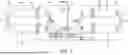
Turning back to FIG. 1, an ante room 24 is positioned between the two clean rooms 20a, 20b, and both of the clean rooms 20a, 20b have doors that only open into the ante room 24. Thus, there is no door or any other opening that connects the two clean rooms 20a, 20b with one another directly. Accordingly, a pharmacist who wants to travel from one of the clean rooms 20a, 20b to the other must pass through the ante room 24 to do so. The ante room 24 thus separates the two clean rooms 20a, 20b for both mechanical protection and biological protection.
The HVAC system 22 includes two sub-systems 26a, 26b (hereinafter referred to as a first sub-system 26a and a second sub-system 26b), one associated with each of the clean rooms 20a, 20b. The first sub-system 26a is illustrated in more detail in FIG. 2. It should be appreciated that the second sub-system 26b (illustrated in FIG. 1) has a similar configuration to the first sub-system 26a. As illustrated, the first sub-system 26a includes three air intakes 28a, 28b, 28c. A first air intake 28a is a return intake that receives air from the first clean room 20a. A second air intake 28b is a return intake that receives air from the ante room 24 (illustrated in FIG. 1). A third air intake 28c receives ambient air from outside of the pharmacy. According to an exemplary embodiment of the present disclosure, during use, no more than approximately four percent (4%) of the air that enters the first sub-system 26a comes from the third air intake 28c. In this embodiment, a substantial majority of the air that enters the first sub-system 26a enters through the first air intake 28a, i.e., is recirculated air that comes from the first clean room 20a. Thus, when the first clean room 20a is sterilized, disinfecting chemicals, such as hydrogen peroxide pass through the first sub-system 26a.
The first sub-system 26a includes two generally parallel fluid paths 30a, 30b (hereinafter referred to as a first fluid path 30a and a second fluid path 30b) that extend from a location where the ducting of the three air intakes 28a, 28b, 28c come together to a single exhaust 32, which is located within the clean room 20a. The first and second fluid paths 30a, 30b can be independently opened and closed by a pair of controlled air dampers 34 (e.g., baffles) or dampers that are located adjacent their respective beginnings (the location where the three air intakes 28a, 28b, 28c come together) and ends (the exhaust 32). The air dampers 34 can be selectively opened and closed under the instructions of a controller (discussed in further detail below), which controls operation of the HVAC system 22. In an exemplary embodiment, the air dampers 34 include electronic actuators that can either open the air dampers 34 to allow fluid flow therethrough or can close the air dampers 34 to prevent fluid flow therethrough. Thus, through control of the air dampers 34, the air can flow through the first fluid path 30a, the second fluid path 30b, both fluid paths 30a, 30b, or neither fluid path 30a, 30b. In FIG. 4, the air dampers 34 within the second fluid path 30b are open and the air dampers 34 within the first fluid path 30a are closed. Accordingly, in this condition, air can only flow through the second fluid path 30b. Thus, maintenance can be performed in the components of the first fluid path 30a without upsetting the operation of the first sub-system 26a.
Each of the first and second fluid paths 30a, 30b includes components for conditioning the air flowing therethrough such that the air that enters the first clean room 20a has a desired temperature and humidity. More specifically, in order from upstream to downstream, each of the first and second fluid paths 30a, 30b includes a pre-filter 36, a pair of evaporator coils 38, a blower 40, a warming heat exchanger 42 and a humidifier 44. All of these components are located between the two air dampers 34 of the respective fluid path 30a, 30b such that air only flows through them when the associated air dampers 34 are opened. Also, as discussed in further detail below, all of these components can be activated and controlled by the controller. In an exemplary embodiment, these components are configured to create a cascading different air pressure between the clean rooms 20a, 20b and the ante room 22 of approximately 0.02 inches of water.
The pre-filter 36 can be any suitable type of pre-filter 36 for capturing particulates in the air flowing through the first sub-system 26a. In some embodiments, the pre-filter 36 may be made at least partially of carbon to capture hydrogen peroxide in the first sub-system 26a prior to it reaching the other components, thereby improving the corrosion resistance of those components.
The evaporator coils 38 are positioned downstream of the filters 36 and receive a cooling fluid (not illustrated) from an external source and can transfer heat from the air in the first sub-system 26a to the cooling fluid to thereby lower the temperature of the air when desired. For example, if the controller is set to lower the temperature in the first clean room 20a, then one or both of the evaporator coils 38 is/are activated. In some other embodiments, each of the first and second fluid paths 30a, 30b can include only a single evaporator coil or can include three or more evaporator coils.
Referring now to FIG. 5, each of the evaporator coils 38 (or evaporators) includes at least one tube 46 that extends across the ducting of the first sub-system 26a. More specifically, in the exemplary embodiment, each evaporator coil 38 includes a single, monolithic tube that extends back and forth across the evaporator coil 38 in serpentine fashion. The tube 46 has an inlet where the cooling fluid is received into the evaporator coil 38 and an outlet where the coolant leaves the evaporator coil 38. A plurality of fins 48 extend between adjacent legs of the tube 46. When activated, the cooling fluid is pumped at a low temperature through the tube 46. Air in the ducting flows across the legs of the tube 46 and the fins 48 and heat is transferred from the air into the tube 46 and fins 48 and ultimately into the cooling fluid, thereby cooling the air. In an example embodiment, the cooling fluid is R-410A refrigerant. However, in some other embodiments, other refrigerant fluids can be employed. In the exemplary embodiment, the fins 48 are attached with the tube 46 via a brazing operation. In other embodiments, the fins 48 may be attached to the tube 46 through soldering, welding, or a mechanical fastener. In the case of welding, the evaporator coil 38 is preheated to a temperature in the range of 145-205° C. and then the temperature at the welding locations, where the tube 46 and fins 48 are joined together, is in the range of 149-204° C.
In the exemplary embodiment, which is illustrated in FIGS. 5 and 6, the evaporator coils 38 are substantially made of aluminum or an aluminum alloy. These materials have been found to provide the evaporator coils 38 with improved resistance to corrosion when exposed to the disinfecting chemicals, such as hydrogen peroxide, as compared to other known materials. More specifically, in the exemplary embodiment, both the tube 46 and the fins 48 are made of aluminum or an aluminum alloy. The temperatures that the heat exchanger is 38 are exposed to during the process of joining the fins 48 with the tube 46 remain below a melting point temperature of the aluminum or aluminum alloy. In an example embodiment, the temperatures remain below 659° C.
In the exemplary embodiment, the legs of the tube 46 are interconnected with one another at curved tube ends 50 on opposite sides of each of the evaporator coils 38. Liquid, such as the hydrogen peroxide disinfecting chemical, can accumulate on these curved tube ends 50. In the exemplary embodiment, one or more fans 51 or blowers are positioned adjacent the evaporator coils 38 and are configured to blow air across the curved tube ends 50 to dry (evaporate) the curved tube ends 50. By drying any liquid that accumulates on the curved tube ends 50, the corrosion resistance of the evaporator coils 38 is improved.
Turning now to FIG. 6, in an exemplary embodiment, a pair of air redirectors 53 are positioned immediately upstream the curved tube ends 50 of the tube 46 for redirecting air in the ducting of the first sub-system 26a away from these areas and thereby further protect the curved tube ends 50 from corrosion. Also illustrated in this figure is a temperature sensor 52, such as an infrared sensor, that is configured to detect temperature gradients at the evaporator coils 38. The temperature sensor 52 is in electrical communication with the controller, thereby allowing the controller to automatically detect any leakages in the tube 46 so that appropriate maintenance can be performed. In the exemplary embodiment, the temperature sensor 52 is positioned downstream of the evaporator coil 38.
Turning back to FIG. 2, the blowers 40 are in electrical communication with the controller and, when activated, pumps the air in the respective fluid paths 30a, 30b towards the exhaust 32. In an embodiment, the blowers 40 have variable speeds for adjusting the flow rate of the air through the fluid paths 30a, 30b.
The warming heat exchangers 42 are in electrical communication with the controller and can take many different forms for heating the air in the fluid paths 30a, 30b when heating is desired. In the exemplary embodiment, the warming heat exchangers 42 are electric heaters that include resistive elements that warm when electricity is passed through them. In some embodiments, the warming heat exchangers can be non-electric, e.g., they can receive a warming fluid that transfers heat to the air in the fluid paths 30a, 30b.
The humidifiers 44 are also in electrical communication with the controller and can be selectively activated to increase the humidity (moisture content) of the air in the fluid paths 30a, 30b. In some embodiments, the humidifiers 44 receives purified water from an external source (not illustrated) and can either gasify the water through evaporation, ultrasonic vibrations, steam production, mist creation, or any suitable means. The humidity added by the humidifiers reduces static within the clean rooms 20a, 20b to protect electronics and bulk powders.
Turning now to FIG. 7, the controller 700 is in electrical communication with all of the air dampers 34, the evaporator coils 38, the blowers 40, and the humidifier 44. The controller can selectively and automatically activate and deactivate any of these components to control the temperature and humidity within both of the clean rooms 20a, 20b (illustrated in FIG. 1). Further, with the air dampers 34, for each of the clean rooms 20a, 20b, the controller 700 is able to open or close first and second fluid paths 30a, 30b. Thus, if a component in one of these fluid paths 30a, 30b needs servicing, the air in the associated clean room 20a can still be conditioned through the use of the other fluid path 30b.
The foregoing detailed description has been presented for purposes of illustration and description. It is not intended to be exhaustive or be limited to the precise form disclosed. Many modifications and variations are possible in light of the above description. The described embodiments were chosen to best explain the principles of the technology and its practical application to thereby enable others skilled in the art to best utilize the technology in various embodiments and with various modifications as are suited to the particular use contemplated. The scope of the technology is defined by the claims appended hereto.
The above-described embodiments, implementations, and aspects have been described in order to allow easy understanding of the present disclosure and do not limit the present disclosure. On the contrary, the disclosure is intended to cover various modifications and equivalent arrangements included within the scope of the appended claims, which scope is to be accorded the broadest interpretation to encompass all such modifications and equivalent structure as is permitted under law.
The word “example” is used herein to mean serving as an example, instance, or illustration. Any aspect or design described herein as “example” is not necessarily to be construed as preferred or advantageous over other aspects or designs. Rather, use of the word “example” is intended to present concepts in a concrete fashion. As used in this application, the term “or” is intended to mean an inclusive “or” rather than an exclusive “or.” That is, unless specified otherwise, or clear from context, “X includes A or B” is intended to mean any of the natural inclusive permutations. That is, if X includes A; X includes B; or X includes both A and B, then “X includes A or B” is satisfied under any of the foregoing instances. In addition, the articles “a” and “an” as used in this application and the appended claims should generally be construed to mean “one or more” unless specified otherwise or clear from context to be directed to a singular form. Moreover, use of the term “an implementation” or “one implementation” throughout is not intended to mean the same embodiment or implementation unless described as such.
Claims
What is claimed is:1. A compounding pharmacy, comprising:
at least one clean room for manually mixing pharmaceutical ingredients to form a specialized product;
the at least one clean room having a heating, ventilation, and air conditioning (HVAC) including at least two fluid paths that extend from at least one air intake to an exhaust within the at least one clean room, each of the at least two fluid paths having at least two air dampers that can be selectively opened to allow flow through the respective fluid path or closed to prevent flow through the respective fluid path, and each of the at least two fluid paths including at least one evaporator coil;
the at least one evaporator coil including at least one tube for conveying a cooling fluid and a plurality of fins; and
wherein the at least one tube and the plurality of fins of the at least one evaporator coil are made of aluminum or an aluminum alloy.
2. The compounding pharmacy as set forth in claim 1, wherein the plurality of fins are brazed or soldered into attachment with the at least one tube.
3. The compounding pharmacy as set forth in claim 2, wherein the aluminum or aluminum alloy is aluminum.
4. The compounding pharmacy as set forth in claim 1, wherein in each of the fluid paths, the air dampers are located upstream and downstream of the at least one evaporator coil.
5. The compounding pharmacy as set forth in claim 4, wherein each of the at least two fluid paths includes, in addition to the at least one evaporator coil, a blower, a filter, a warming heat exchanger, and a humidifier.
6. The compounding pharmacy as set forth in claim 5, wherein in each of the at least two fluid paths, the filter includes carbon and is positioned upstream of the at least one evaporator coil.
7. The compounding pharmacy as set forth in claim 1, wherein the at least one clean room includes at least two clean rooms, and wherein for each of the at least two clean rooms, the HVAC system includes at least two fluid paths,
wherein each of the at least two fluid paths has at least two air dampers that can be selectively opened to allow flow through the respective fluid path or closed to prevent flow through the respective fluid path, and
wherein at least one evaporator coil is positioned in each of the at least two fluid paths for each of the at least two clean rooms.
8. The compounding pharmacy as set forth in claim 1, wherein the at least one tube of the at least one evaporator coil extends with a plurality of legs through a serpentine pattern back and forth across the at least one evaporator coil, wherein
adjacent ones of the plurality of legs are interconnected with one another by curved tube ends, and
further including a fan positioned adjacent the curved tube ends.
9. The compounding pharmacy as set forth in claim 1, wherein the at least one tube of the at least one evaporator coil extends with a plurality of legs through a serpentine pattern back and forth across the at least one evaporator coil, wherein
adjacent ones of the plurality of legs are interconnected with one another by curved tube ends, and
further including at least one air diverter positioned upstream of the at least one evaporator coil for diverting air in the HVAC system away from the curved tube ends.
10. A compounding pharmacy for creating a compounded pharmaceutical, comprising:
a first clean room and a second clean room, the clean rooms being for manually mixing pharmaceutical ingredients;
a heating, ventilation, and air conditioning (HVAC) system for conditioning air in the first and second clean rooms;
the HVAC system including a first sub-system for conditioning the air in the first clean room and a second sub-system for conditioning the air in the second clean room;
each of the first and second sub-systems having a first fluid path and a second fluid path that extend from at least one air intake to an exhaust;
at least one evaporator coil positioned in each of the first and second fluid paths of each of the first and second sub-systems, the at least one evaporator coil including at least one tube for conveying a cooling fluid and a plurality of fins; and
wherein the at least one tube of the at least one evaporator coil is made of aluminum or an aluminum alloy.
11. The compounding pharmacy as set forth in claim 10, wherein the plurality of fins of the at least one evaporator coil is made of aluminum or an aluminum alloy.
12. The compounding pharmacy as set forth in claim 11, wherein the aluminum or aluminum alloy is aluminum.
13. The compounding pharmacy as set forth in claim 10, wherein each of the fluid paths of each of the sub-systems has at least two air dampers that can be selectively opened to allow flow through the respective fluid path or closed to prevent flow through the respective fluid path.
14. The compounding pharmacy as set forth in claim 13, wherein in each of the fluid paths of each of the sub-systems, the HVAC system further includes a blower, a filter, a warming heat exchanger, and a humidifier, and
wherein the at least one evaporator coil, the blower, the filter, the warming heat exchanger, and the humidifier are all located between the at least two air dampers of the respective fluid flow path.
15. The compounding pharmacy as set forth in claim 14, wherein in each of the fluid paths of each of the sub-systems, the filter is positioned upstream of the at least one evaporator coil and includes carbon.
16. A method of operating a compounding pharmacy, the compounding pharmacy including;
at least one clean room for manually mixing pharmaceutical ingredients to form a specialized product,
a heating, ventilation, and air conditioning (HVAC) system including at least one evaporator coil for cooling air for the at least one clean room,
the at least one evaporator coil including at least one tube for conveying a cooling fluid and a plurality of fins, and
wherein the at least one tube of the at least one evaporator coil is made of aluminum or an aluminum alloy; and the method further including the steps of;
sterilizing the at least one clean room with a sterilizing chemical, and
conditioning the air in the at least one room with the HVAC system.
17. The method as set forth in claim 16, wherein the plurality of fins of the at least one evaporator coil are made of aluminum or an aluminum alloy.
18. The method as set forth in claim 17, wherein the aluminum or aluminum alloy is aluminum.
19. The method as set forth in claim 16, wherein for the at least one clean room, the HVAC system includes at least two fluid paths that extend from at least one air intake to an exhaust within the at least one clean room;
wherein each of the at least two at least two fluid paths has at least two air dampers that can be selectively opened to allow flow through the respective fluid path or closed to prevent flow through the respective fluid path; and further including the step of:
selectively opening and closing each of the at least two fluid paths by opening and closing the at least two air dampers.
20. The method as set forth in claim 19, wherein each of the at least two fluid paths further includes a filter, and further including the step of directing air in the HVAC system through the filter prior to the air reaching the at least one evaporator coil.
Images & Drawings included:


Sources:
- United States Patent and Trademark Office - verify current appl. status at the USPTO↗
Recent applications in this class:
- » 20260126189 2026-05-07
Cleanroom System and Vehicle Mounted with Cleanroom System - » 20260110448 2026-04-23
WORK SPACE FORMING EQUIPMENT, WORK METHOD, AND MANAGEMENT SPACE FACILITY - » 20260104171 2026-04-16
CLEAN ROOM FACILITY - » 20260098648 2026-04-09
INDOOR AIR POLLUTION-FREE CLEANROOM SYSTEM ACHIEVING ARTIFICIAL INTELLIGENCE GREEN AND HEALTH BUILDING STANDARDS - » 20260085846 2026-03-26
PREVENTION OF CONTAMINATION OF SUBSTRATES DURING PRESSURE CHANGES IN PROCESSING SYSTEMS - » 20260029143 2026-01-29
Mobile, Expandable Cleanroom Systems, Methods, and Devices - » 20250369635 2025-12-04
CLEANROOM ARRANGEMENT AND METHOD FOR RAPIDLY PROVIDING A CLEANROOM - » 20250341322 2025-11-06
MOBILE CLEAN ROOM - » 20250102162 2025-03-27
FIELD-CHANGEABLE MULTI-MODE CLEANROOMS AND LABORATORIES - » 20250052436 2025-02-13
Negative Pressure Envelop for Controlled Environment Rooms