INDOOR UNIT AND AIR CONDITIONER
US20260177280A1
2026-06-25
19/126,111
2023-02-02
Smart Summary: An air conditioner has an indoor unit that helps circulate a special fluid called refrigerant. This unit includes a base and a sensor to monitor the refrigerant. The sensor is made up of a main body, a lid, and a sealing part to keep everything tight. There are surfaces on the main body and lid that press against each other to ensure a good seal. This design helps the air conditioner work efficiently by preventing leaks in the refrigerant circuit. 🚀 TL;DR
Abstract:
An indoor unit of an air conditioner having a refrigerant circuit to circulate a refrigerant includes a base, a refrigerant sensor unit, and a fixer. The housing of the refrigerant sensor unit includes a housing main body, a lid, and a sealing member. The housing main body includes a first sealing surface which faces one side in a joining direction and contacts the sealing member, and a first opposing surface which faces another side in the joining direction. The lid includes a second sealing surface which faces the another side and contacts the sealing member, and a second opposing surface which faces the one side. A first pressing surface faces the one side and contacts the first opposing surface. A second pressing surface contacts the second opposing surface, and a fixing portion. The housing is sandwiched between the first pressing surface and the second pressing surface.
Applicant:
Interested in similar patents?
Get notified when new applications in this technology area are published.
Classification:
F24F13/20 » CPC main
Details common to, or for air-conditioning, air-humidification, ventilation or use of air currents for screening Casings or covers
F24F11/89 » CPC further
Control or safety arrangements Arrangement or mounting of control or safety devices
Description
TECHNICAL FIELD
The present disclosure relates to an indoor unit, and an air conditioner.
BACKGROUND ART
Conventionally, an air conditioner which uses a flammable refrigerant, includes a refrigerant sensor unit attached to an indoor unit thereof is known (for example, refer to Patent Document 1). The refrigerant sensor unit detects refrigerant in a case where the refrigerant has leaked form a heat exchanger.
CITATION LIST
Patent Documents
Patent Document 1: Japanese Unexamined Patent Application, first publication No. 2016-90108
SUMMARY OF INVENTION
Problem to be Solved by the Invention
It is preferable to have a refrigerant sensor unit be disposed close to a heat exchanger that circulates a refrigerant. Since it is easy for water vapor to build up around the vicinity of the heat exchanger, development of a refrigerant sensor unit possessing high water resistance performance is sought after.
The present disclosure is made with above problem in mind, and an object thereof is to provide an indoor unit having a refrigerant sensor unit which possesses high water resistance performance.
Means to Solve the Problem
An embodiment of an indoor unit according to the present disclosure includes a refrigerant circuit to circulate a refrigerant, and is an indoor unit of an air conditioner that includes a base, a refrigerant sensor unit that is joined from one side in a joining direction to the base, and a fixer that fixes the refrigerant sensor unit to the base. The refrigerant sensor unit includes a sensor main body that detects the refrigerant that has gasified, and a housing that is provided with an accommodation space which accommodates the sensor main body. The housing includes a housing main body, a lid that is joined to the housing main body from the one side in the joining direction, and that surrounds the accommodation space along with the housing main body, and a sealing member that is sandwiched between the housing main body and the lid. The housing main body includes a first sealing surface which faces the one side in the joining direction and contacts the sealing member, and a first opposing surface which faces another side in the joining direction. The lid includes a second sealing surface which faces the another side in the joining direction and contacts the sealing member, and a second opposing surface which faces the one side in the joining direction. The base includes a first pressing surface which faces the one side in the joining direction and contacts the first opposing surface. The fixer includes a second pressing surface which contacts the second opposing surface, and a fixing portion which is fixed to the base. The housing is sandwiched between the first pressing surface and the second pressing surface.
An embodiment of the air conditioner according to the present disclosure includes the indoor unit and the refrigerant circuit mentioned above, and an outdoor unit.
Effects of the Invention
According to the present disclosure, it is possible to provide an indoor unit that includes a refrigerant sensor unit the possess high water resistance performance, and an air conditioner.
BRIEF DESCRIPTION OF DRAWINGS
FIG. 1 A schematic diagram that shows an outline configuration of an air conditioner in a present embodiment.
FIG. 2 A perspective view that shows an indoor unit in the present embodiment.
FIG. 3 An exploded perspective view that shows the indoor unit in the present embodiment.
FIG. 4 A perspective view that shows a refrigerant sensor unit in a state of being removed from an inside of an indoor unit heat exchanger.
FIG. 5 A perspective view that shows a base in the present embodiment.
FIG. 6 A perspective view that shows the refrigerant sensor unit in the present embodiment.
FIG. 7 An exploded perspective view that shows the refrigerant sensor unit in the present embodiment.
FIG. 8 A cross-sectional view of the refrigerant sensor unit in the present embodiment.
FIG. 9 A perspective view of the refrigerant sensor unit and a fixer in the present embodiment.
FIG. 10 A perspective view that shows a first step of a preliminary process in the present embodiment.
FIG. 11 A perspective view that shows a second step of the preliminary process in the present embodiment.
FIG. 12 A perspective view that shows the first step of a joining process in the present embodiment, as seen from one side in a joining direction.
FIG. 13 A perspective view that shows the first step of the joining process in the present embodiment, as seen from the another side in the joining direction.
FIG. 14 A perspective view that shows the second step of the joining process in the present embodiment, as seen from the another side in the joining direction.
DESCRIPTION OF EMBODIMENTS
Hereinafter, embodiments of the present disclosure are explained with reference to the drawings. A top-bottom direction is suitably shown on the drawings by a Z axis. A side that the arrow of the Z axis points towards (+Z side) out of sides of the top-bottom direction is “above”. A side opposite to the side that the arrow of the Z axis points towards (−Z side) out of sides of the top-bottom direction is “below”. An orientation of an indoor unit 10 in the top-bottom direction used in explanations of the present embodiment serves only as an example, and in no way limits the joining orientation of the indoor unit 10.
FIG. 1 is a schematic diagram that shows an overall configuration of an air conditioner 100 according to the present embodiment. As shown in FIG. 1, the air conditioner 100 includes the indoor unit 10, an outdoor unit 20, and a refrigerant circuit 30. The indoor unit 10 is disposed indoors. The outdoor unit 20 is disposed outdoors. The indoor unit 10 and the outdoor unit 20 are connected to one another using the refrigerant circuit 30 which circulates the refrigerant 33. The outdoor unit 10 and the indoor unit 20 are heat exchange units that conduct heat exchange with the air.
By having a refrigerant 33 that flows within the refrigerant circuit 30, and the indoor unit 10 conduct heat exchange with air indoors, it is possible for the air conditioner 100 to adjust a temperature of the air indoors. A refrigerant such as a fluorine based refrigerant with a low global warming potential (GWP: Global Warming Potential), or a hydrocarbon based refrigerant or the like may be mentioned as examples of the refrigerant 33. Any one of refrigerants R1234yf, R1234ze, R32, and R290 used as a single refrigerant, a mix of two or more of said refrigerants, or in combination with other refrigerants may also be mentioned as examples of the refrigerant 33. A mixed refrigerant that includes R1132 (E), or a mixed refrigerant that includes R1123 may be mentioned as examples of the refrigerant 33. Mixed refrigerants R516A, R445A, R444A, R454C, R444B, R454A, R455A, R457A, R459B, R452B, R454B, R447B, R447A, R446A, and R459A may also be mentioned as examples of the refrigerant 33.
The outdoor unit 20 includes a compressor 21, an outdoor heat exchanger 23, a flow rate adjustment valve 24, a blower 25, and a four-way valve 22. The compressor 21, the outdoor heat exchanger 23, the flow rate adjustment valve 24, and the four-way valve 22 are connected using the refrigerant circuit 30.
The four-way valve 22 is disposed on a part that is connected to a discharge side of the compressor 21, out of the refrigerant circuit 30. By switching a part of the refrigerant circuit 30, the four-way valve 22 causes a direction of flow of the refrigerant 33 to reverse within the refrigerant circuit 30. In case where the pathway of the four-way valve 22 shown by a solid line in FIG. 1 is connected to the four-way valve 22, the refrigerant 33 flows within the refrigerant circuit 30 in the direction of the solid line shown in FIG. 1. On the other hand, in a case where the pathway of the four-way valve 22 shown by a dashed line in FIG. 1 is connected to the four-way valve 22, the refrigerant 33 flows in the direction of the dashed line within the refrigerant circuit 30 shown in FIG. 1.
The indoor unit 10 includes a centrifugal blower 40, and an indoor heat unit exchanger (heat exchanger) 14 disposed around the centrifugal blower 40. It is possible for the indoor unit 10 to have a cooling operation where air of the room the indoor unit 10 is disposed in is cooled, and it is possible to have a heating operation where air of the room the indoor unit 10 is disposed in is heated.
When the indoor unit 10 is operated in the cooling operation, the refrigerant 33 that flows within the refrigerant circuit 30 flows in the direction shown by solid lines in FIG. 1. In other words, when the indoor unit 10 is operated in the cooling operation, the refrigerant 33 that flows within the refrigerant circuit 30 circulates so as to return to the compressor 21 after passing through the compressor 21, the heat exchanger 23 of the outdoor unit 20, the flow rate adjustment valve 24, and the indoor unit heat exchanger 14 of the indoor unit 10 in such an order. During the cooling operation, the heat exchanger 23 of the outdoor unit 20 functions as a condenser, and the indoor unit heat exchanger 14 of the indoor unit 10 functions as an evaporator.
On the other hand, when the indoor unit 10 is operated in the heating operation, the refrigerant 33 that flows within the refrigerant circuit 30 flows in the direction shown by dashed lines in FIG. 1. In other words, when the indoor unit 10 is operated in the heating operation, the refrigerant 33 that flows within the refrigerant circuit 30 circulates so as to return to the compressor 21 after passing through the compressor 21, the indoor unit heat exchanger 14 of the indoor unit 10, the flow rate adjustment valve 24, and the heat exchanger 23 on an inside of the outdoor unit 20 in such an order. During the heating operation, the heat exchanger 23 of the outdoor unit 20 functions as the evaporator, and the indoor unit heat exchanger 14 on an inside of the indoor unit 10 functions as the condenser.
Next, the indoor unit 10 of the present embodiment is explained in more detail.
FIG. 2 is a perspective view that shows the indoor unit 10. FIG. 3 is an exploded perspective view that shows the indoor unit 10. Furthermore, a decoration panel that covers a bottom surface of the indoor unit 10 is omitted from both FIG. 2 and FIG. 3.
As shown in FIG. 2 and in FIG. 3, the indoor unit 10 includes the centrifugal blower 40 with a rotation axis R being a center of rotation thereof. In the present embodiment, a direction in which the rotation axis R extends is the top-bottom direction. In the explanations below, there are cases where an axial direction of the rotation axis R, in other words a direction parallel to the Z axis, is simply referred to as an “axial direction”. There are cases where a circumferential direction having the rotation axis R as a center thereof is simply referred to as a “circumferential direction”. In the explanations below, an “outer radial side” means a side out of sides in the radial direction that moves away from the rotation axis R, and an “inner radial side” is a side out of sides in the radial direction that moves closer to the rotation axis R.
The indoor unit 10 in the present embodiment is a ceiling type embedded indoor unit, provided so as to be embedded within a ceiling. As shown in FIG. 3, along with the aforementioned centrifugal blower 40 and the indoor unit heat exchanger 14, the indoor unit 10 includes a housing 11, a refrigerant sensor unit 50, a drain pan 41, a bell mouth 42, a controller 43, and a decorative panel (omitted).
The housing 11 covers the centrifugal blower 40 and the indoor unit heat exchanger 14 from above, and from the side. The housing 11 is fixed to the ceiling into which the indoor unit 10 is installed. A fan motor of the centrifugal blower 40, the indoor unit heat exchanger 14, and the drain pan 41 are fixed to the housing 11. The drain pan 41 covers the indoor unit heat exchanger 14 from below. The drain pan 41 is a rectangular when viewed from the axial direction. A discharge outlet 41a is provided on the drain pan 41. The drain pan 41 catches condensation water that is generated along with heat exchange of the indoor unit heat exchanger 14. The bell mouth 42 is fixed to the drain pan 41. The bell mouth 42 is disposed below the centrifugal blower 40. An intake 42a is provided on the bell mouth 42. The intake 42a is a circular shape having the rotation axis R as a center thereof. The controller 43 is fixed to a bottom surface of the bell mouth 42. The controller 43 includes a control board (omitted from the drawings) that controls each part of the indoor unit 10. The controller 43 conducts control of configuration parts of the air conditioner 100 needed for carrying out cooling and heating operations. A wire that extends from the refrigerant sensor unit 50 is connected thereto, and the controller 43 determines the presence of a refrigerant leak or lack thereof based on detection results of the gas refrigerant at the refrigerant sensor unit 50.
The centrifugal blower 40 includes an impeller 40a, and a fan motor (omitted from the drawings) that causes the impeller 40a to rotate. The impeller 40a covers the fan motor from below. The impeller 40a is rotated about the rotation axis R. The centrifugal blower 40 takes air into the room from the intake 42a, and blows the air to the outer radial side thereof. The indoor unit heat exchanger 14 is disposed on an outer radial side of the centrifugal blower 40.
The indoor unit heat exchanger 14 includes a rectangular heat exchanger main body 14b as seen from the axial direction, and a pipe connector 14a which is connected to a pipe that extends from the heat exchanger main body 14b. The heat exchanger main body 14b surrounds the centrifugal blower 40 from the outside in the radial direction. The refrigerant flows on an inside of the heat exchanger main body 14b. The heat exchanger main body 14b conducts heat exchange with the air that is brought in by impeller 40. The refrigerant sensor unit 50 is attached to the inside of the heat exchanger main body 14b in the radial direction.
The refrigerant sensor unit 50 is disposed on the inner radial side of a pipe connector 14a of the indoor unit heat exchanger 14. The refrigerant sensor unit 50 is disposed between the centrifugal blower 40 and the indoor unit heat exchanger 14. The refrigerant sensor unit 50 is disposed above the drain pan 41. When refrigerant leaks out from the indoor unit heat exchanger 14, the refrigerant gasifies and becomes a gas refrigerant. Due to being heavier than air, the gas refrigerant flows to the bottom and accumulates above in the drain pan 41. The refrigerant sensor unit 50 detects the gas refrigerant that accumulates above in the drain pan 41. Compared to other parts, it is typically easier for leaked out refrigerant to accumulate at the pipe connector 14a of the indoor unit heat exchanger 14. According to the present embodiment, by disposing the refrigerant sensor unit 50 on an outer radial side of the pipe connector 14a, it is possible to immediately have leaked out gas refrigerant from the pipe connector 14a be detected by the refrigerant sensor unit 50.
FIG. 4 is a perspective view that shows the refrigerant sensor unit 50 in a state of being removed from an inside of an indoor unit heat exchanger 14.
As shown in FIG. 4, the refrigerant sensor unit 50 is attached to the inside of the indoor unit heat exchanger 14 via a base 90. In other words, the indoor unit 10 includes a base 90. The base 90 is fixed to an inner surface that faces the radial direction of the indoor unit heat exchanger 14.
In the explanations below, a direction in which the refrigerant sensor unit 50 is joined to the base 90 is referred to as a joining direction D3. The joining direction D3 is appropriately shown on the drawings using an arrow. In the explanations below, a direction in which the tip of the arrow of the joining direction D3 points to in each drawing is referred to as the “other side (+D3) in the joining direction”, while a direction that is opposite is referred to as the “one side (−D3) in the joining direction”. In the present embodiment, the refrigerant sensor unit 50 is joined to the base 90 from the one side (−D3) in the joining direction. In the present embodiment, the joining direction D3 is a direction that is orthogonal to the up-down direction, and is a direction that coincides with the rotational axis R.
FIG. 5 is a perspective view that shows the base 90. The base 90 includes a main plate 90a, a pair of side plates 90b and 90c, and an auxiliary plate 95. In the present embodiment, the main plate 90a and the pair of side plates 90b and 90e are configured from a single plate member. On the other hand, the auxiliary plate 95 is fixed to a surface on the one side (a locking surface 90e) of the main plate 90a.
The main plate 90a is a flat plate that is disposed so as to be orthogonal to the joining direction D3. Each of the side plates 90b and 90c is connected to an end on the one side, and on the another side of the main plate 90a in the circumferential direction. The side plates 90a and 90b are bent in the radial direction with respect to the main plate 90a. Each of the side plates 90b and 90c is fixed to the inner surface that faces the radial direction of the indoor unit heat exchanger 14.
The main plate 90a includes a first pressing surface 90d which faces the one side (−D3) in the joining direction, and the locking surface 90e that faces the another side (+D3) in the joining direction. In other words, the first pressing surface 90d and the locking surface 90e are surfaces that face directions of the main plate 90a which are opposite to one another. An attachment hole 91 and an insertion hole 92 which penetrate the main plate 90a in the joining direction D3 are provided on the main plate 90a. The attachment hole 91 and the insertion hole 92 are disposed so as to align in the top-bottom direction.
The attachment hole 91 includes a first hole 91a, and a second bole 91b that connects to an upper end of the first hole 91a. The first hole 91a and the second hole 91b are rectangular shapes. A dimension of the second hole 91b in the top-bottom direction is smaller than a dimension of the first hole 91a in the top-bottom direction. A dimension of the second hole 91b in the left-right direction is smaller than a dimension of the first hole 91a in the left-right direction. The second hole 91b is approximately located on the center in the left-right direction of the first hole 91a.
The insertion hole 92 is located below the attachment bole 91. The insertion hole 92 is rectangular. A dimension of the insertion hole 92 in the top-bottom direction is smaller than the dimension of the first hole 91a in the top-bottom direction. The dimension of the insertion hole 92 in the left-right direction is smaller than the dimension of the first hole 91a in the left-right direction.
The auxiliary plate 95 includes a fixed plate 95a and a bent plate 95b. The fixed plate 95a is fixed to the locking surface 90e of the main plate 90a. The fixed plate 95a extends in the left-right direction. The fixed plate 95a is disposed between the attachment hole 91 and the insertion hole 92. The bent plate 95b is bent and formed on the another side (+D3) in the joining direction from a lower end edge of the fixed plate 95a. The bent plate 95b is located above the insertion hole 92. The bent plate 95b extends to the another side (+D3) side in the joining direction, from an upper end edge of the insertion hole 92. The bent plate 95b is disposed so as to be orthogonal to the top-bottom direction. A through hole 95h, which penetrates the bent plate 95b in the top-bottom direction, is provided on the bent plate 95b. A nut 99 into which a thread hole 99h is provided on a top surface of the bent plate 95b. A center line of the nut 99h coincides with a center line of the thread hole 95h. A diameter of the through hole 95h is sufficiently larger than a diameter of the thread hole 99h.
The nut 99 in the present embodiment is a separate part that is fixed to the top surface of the bent plate 95b. However, the nut 99 may be configured by forming a female thread on an inner surface of the through hole formed by burring processing on the bent plate 95b. In the present embodiment, the bent plate 95b is a part of the auxiliary plate 95 that is fixed to the main plate 90a. However, the bent plate 95b may be formed by bending a part of the main plate 90a.
FIG. 6 is a perspective view that shows the refrigerant sensor unit 50. FIG. 7 is an exploded perspective view that shows the refrigerant sensor unit 50. In FIG. 7, the refrigerant sensor unit 50 is shown fixed to the base 90 along with a fixer 80.
As shown in FIG. 6, the refrigerant sensor unit 50 includes a sensor main body 70 and a housing 60. An accommodation space A that accommodates the sensor main body 70, a refrigerant intake 60a which guides the gas refrigerant to the accommodation space A, and an extraction hole 60h through which a wire 79 is extracted to the outside from the accommodation space A, are formed in the housing 60. The wire 79 extracted to the outside from the extraction hole 60h is connected to a controller 43 (refer to FIG. 3).
As shown in FIG. 7, the sensor main body 70 includes a circuit board 73, a sensor element 71, an element case 72, and a wire 79. The circuit board 73 is fixed to an inner surface of the housing 60. The circuit board 73 extends towards the top-bottom direction. A plurality of elements including sensor elements 71 are formed on the circuit board 73. The sensor element 71 detects the gas refrigerant. The sensor element 71 is surrounded and protected by the element case 72. A cylindrical member 75 is attached to the element case 72. The cylindrical member 75 is a sponge member configured of resin material. The cylindrical member 75 is a cylinder that surrounds an outer surface of the element case 72. An outer shape of the cylindrical member 75 is shaped as a square. The cylindrical member 75 contacts the inner surface of the housing 60. The cylindrical member 75 forms a pathway for the gas refrigerant at the accommodation space A to reach the sensor element 71.
The housing 60 includes a housing main body 61, a lid 62, and a sealing member 69. The housing main body 61 and the lid 62 are joined to one another in the joining direction D3. The housing main body 61 and the lid 62 surround the accommodation space A.
The housing main body 61 includes a first box 61b, a first flange 61c, a guide rib 61e, a guide protrusion 61p, a pair of protrusions 61d, and a first hook 64. The first box 61b includes a bottom surface 61g onto which the refrigerant intake 60a, which is disposed so as to be orthogonal to the direction D3, is disposed. A first opening 61a that opens to the one side (−D3) in the joining direction is provided on the first box 61b.
The first flange 61c is connected to an outer edge of the first opening 61a. The first flange 61c protrudes in a direction that is orthogonal to the joining direction D3, and that moves away from the first opening 61a. The first flange 61c surrounds the first opening 61a as seen from the joining direction D3. The first flange 61c includes a first sealing surface 61f that faces the one side (−D3) in the joining direction. The first sealing surface 61f is a flat surface that is orthogonal to the joining direction D3. The guide protrusion 61p that protrudes to the one side (−D3) in the joining direction is provided on an outer edge of the first sealing surface 61f.
As shown in FIG. 6, a plurality of first ribs 61h and 61k are provided on a surface that faces the another side (+D3) in the joining direction of the first flange 61c. In other words, the housing main body 61 includes the plurality of first ribs 61h and 61k. The plurality of first ribs 61h and 61k protrude to the another side (+D3) in the joining direction. The plurality of ribs 61h and 61k include one frame rib 61h, and a plurality of bridge ribs 61k. The frame rib 61h is a frame that extends along an outer edge of the first flange 61c. The frame rib 61h surrounds an outer surface of the first box 61b as seen from the joining direction D3. The bridge rib 61k connects an inner surface of the frame rib 61h, an outer surface of the first box 61b, and the first flange 61c. The plurality of bridge ribs 61k are disposed so as to align in the direction in which the first flange 61c extends.
The base 90 is disposed on the another side (+D3) in the joining direction of the housing main body 61. The first box 61b is fitted to the first hole 91a of the base 90. Accordingly, tip surfaces of the first ribs 61h and 61k face and are in contact with the base 90. The tip surfaces of the first ribs 61h and 61k are referred to as a first opposing surface 61i. In other words, the housing main body 61 includes a first opposing surface 61i that faces the another side (+D3) in the joining direction. The first opposing surface 61i is a surface that faces a side opposite to the side the first sealing surface 61f faces.
As shown in FIG. 7, the guide rib 61e extends along an inner edge on the first opening 61a side of the first sealing surface 61f. The guide rib 61e surrounds the first opening 61a, as seen from the joining direction D3. The guide rib 61e protrudes to the one side (−D3) in the joining direction, with respect to the first sealing surface 61f.
The pair of protrusions 61d are side surfaces of the first flange 61c, and are disposed on surfaces that face opposite sides from one another. The pair of protrusions 61d are disposed on both sides of the first opening 61a, so as to sandwich the first opening 61a. The pair of protrusions 61d are each orthogonal to the joining direction D3, and each protrude in a direction that moves away from the first opening 61a. A tip surface 61t of the protrusion 61d inclines in a direction in which a protrusion height thereof increases as the tip surface 61t moves away from the lid 62 in the joining direction D3.
The first hook 64 is provided on a lower end of the housing main body 61 and protrudes below the housing main body 61. The first hook 64 is provided on a side surface of the first flange 61c. The first hook 64 includes a first column 64a and a first claw 64b. The first column 64a is a column that extends in a direction which is orthogonal to the joining direction D3, and that moves away from the accommodation space A. The first claw 64b is located on a tip of the first column 64a, and protrudes to the another side (+D3) in the joining direction. The first claw 64b is a plate that is orthogonal to the extension direction of the first column 64a. A surface that faces the one side (−D3) in the joining direction of the first claw 64b and a surface that faces the one side (−D3) in the joining direction of the first column 64a are surfaces that are continuous with the first sealing surface 61f.
In the explanations below, the direction in which the first column 64a extends is referred to as a “first direction D1”. A direction that is orthogonal to both the joining direction D3 and the first direction D1 is a “second direction D2”. Where appropriate, the first direction D1 and the second direction D2 are shown on the drawings using arrows. In the explanations below, a direction in which the tip of the arrow of the first direction D1 points to in each drawing is referred to as the “other side (+D1) in the first direction”, while a direction that is opposite is referred to as the “one side (−D1) in the first direction”. Similarly, a direction in which the tip of the arrow of the second direction D2 points to in each drawing is referred to as the “other side (+D2) in the second direction”, while a direction that is opposite is referred to as the “one side (−D2) in the second direction”. In the present disclosure, the first column 64a protrudes towards the another side (+D1) side in the first direction, from the side surface of the first flange 61c. The first claw 64b is provided on an end on the another side (+D1) in the first direction of the first column 64a. In the present embodiment, the first direction DI is a top-bottom direction. In the present embodiment, the second direction D2 is a circumferential direction about the rotation axis R.
The lid 62 includes a second box 62b, a second flange 62c, a pair of arms 62d, a second hook 65, and a locking hook 63. A second opening 62a that opens to the another side (+D3) in the joining direction is provided on the second box 62b. The second opening 62a opposes the first opening 61a. By joining the lid 62 to the housing main body 61, the first opening 61a and the second opening 62a overlap one another. Accordingly, an inner space of the first box 61b and an inner space of the second box 62b connect and configure the accommodation space A.
The second flange 62c is connected to an outer edge of the second opening 62a. The second flange 62c protrudes in a direction that is orthogonal to the joining direction D3, and that moves away from the second opening 62a. The second flange 62c surrounds the second opening 62a as seen from the joining direction D3. The second flange 62c includes a second sealing surface 62f that faces the another side (+D3) in the joining direction. The second sealing surface 62f is a flat surface that is orthogonal to the joining direction D3. The second sealing surface 62f faces the first sealing surface 61f in the joining direction D3. The sealing member 69 is disposed between the first sealing surface 61f and the second sealing surface 62f.
A recess 62p is provided on an outer edge of the second sealing surface 62f. In the present embodiment, the recess 62p is a notch that recesses to the top from below the second flange 62c. The guide protrusion 61p which is provided on the first sealing surface 61f is inserted through the recess 62p. The guide protrusion 61p and the recess 62p are visual markers used when confirming the top-bottom directions of the housing main body 61 and the lid 62. If the guide protrusion 61p is not inserted through the recess 62p, it is not possible to join the housing main body 61 and the lid 62 to one another. According to the present embodiment, by providing each of the guide protrusion 61p and the recess 62p in the housing main body 61 and the lid 62, it is possible to suppress having the lid 62 be joined to the housing main body 61 in a reverse manner in the top-bottom direction. In other words, it is possible to suppress assembly errors during the assembly process, and it is possible to increase reliability of the assembly process. In the present embodiment, a case where the guide protrusion 61p is provided on the first sealing surface 61f, and the recess 62p is provided on the second sealing surface 62f is explained. However, the guide protrusion 61p may be provided on the second sealing surface 62f, and the recess 62p may be provided on the first sealing surface 61f. In other words, it is sufficient to have the guide protrusion 61p be provided on an outer edge of one of the first sealing surface 61f and the second sealing surface 62f, and the recess 62p be provided on the outer edge of the other of the first sealing surface 61f and the second sealing surface 62f.
A plurality of second ribs 62k are provided on a surface that faces the one side (−D3) in the joining direction of the second flange 62c. In other words, the lid 62 includes the plurality of second ribs 62k. The plurality of second ribs 62k protrude to the one side (−D3) in the joining direction. The plurality of second ribs 62k are disposed on a lower end of the lid 62, and extend in the top-bottom direction. The plurality of second ribs 62k are disposed so as to align in a direction along a bottom end edge of the second flange 62c. The second ribs 62k connect the second box 62b to the second flange 62c.
A pressing pressure portion 81, to be mentioned later on, of the fixer 80 is disposed on the one side (−D3) in the joining direction of the lid 62. Accordingly, tip surfaces of the second ribs 62k face and contact the pressing pressure portion 81. Here, tip surfaces of the second ribs 62k are referred to as a “second opposing surface 62i”. In other words, the lid 62 includes the second opposing surface 62i, which faces the one side (−D3) in the joining direction. The second opposing surface 62i is a surface that faces a side opposite to the side which the second sealing surface 62f faces.
The pair of arms 62d are connected to the second flange 62c. The pair of arms 62d are disposed on both sides of the second opening 62a. Each of the pair of arms 62d includes a pair of link portions 62m which extend to the another side (+D3) in the joining direction from the second flange 62c, and a link locking portion 62j that connects the pair of link portions 62m to one another.
By joining the lid 62 to the housing main body 61, the protrusions 61d of the housing main body 61 are inserted through a portion surrounded by the pair of link portions 62m, the link locking portion 62j, and outer edges of the second flange 62c. By locking the pair of protrusions 61d to the pair of link locking portions 62j, the lid 62 is fixed to the housing main body 61. Since the tip surface 61t of the protrusion 61d is inclined, the link locking portion 62j slides along the tip surface 61t of the protrusion 61d when joining the lid 62 to the housing main body 61, elastically deforming the pair of arms 62d. Accordingly, an operator is able to easily lock the arms 62d to the protrusions 61d.
In the present embodiment, a case where the pair of arms 62d are provided on the lid 62, and the pair of protrusions 61d are provided on the bousing main body 61 is explained. However, the pair of arms 62d may be provided on the housing main body 61, and the pair of protrusions 61d provided on the lid 62. In other words, it is possible to have one of the housing main body 61 or the lid 62 include the pair of protrusions 61d, while having the other of the housing main body 61 or the lid 62 include the pair of arms 62d to which the pair of protrusions 61d are locked.
In the present embodiment, during the assembly process of the refrigerant sensor unit 50, an operator joins the sensor main body 70 to the first opening 61a, while the first opening 61a of the housing main body 61 is in a state of facing upwards. By providing an arm in the housing main body 61, the arm protrudes above with respect to the first opening 61a, and there is a risk of a decrease in workability of the operator. As such, when adopting an assembly process such as in the present embodiment, where the sensor main body 70 is joined to the housing main body 61, it is preferable to have the arm 62d be provided on the lid 62.
As shown in FIG. 6, the locking hook 63 is provided on an upper end of the lid 62, and extends above and towards the another side (+D3) in the joining direction. The locking hook 63 is provided on a side surface of the second flange 62c. The locking hook 63 includes a first protrusion 63a, a second protrusion 63b, and a locking plate 63c. The first protrusion 63a extends above from the top surface of the second flange 62c. The second protrusion 63b extends to the another side (+D3) in the joining direction, from an upper end of the first protrusion 63a. The locking plate 63c extends above from a tip on the another side (+D3) in the joining direction of the second protrusion 63b. The locking plate 63c is a plate which is orthogonal to the joining direction D3. In a state where the refrigerant sensor unit 50 is joined to the base 90, a surface that faces the one side (−D3) in the joining direction of the locking plate 63c contacts the base 90. A surface that faces the one side (−D3) in the joining direction of the locking plate 63c is referred to as a “third opposing surface 63f”. In other words, the locking hook 63 includes a third opposing surface 63f that faces the one side (−D3) in the joining direction.
As shown in FIG. 7, the second hook 65 is provided on a lower end of the lid 62, and protrudes below the lid 62. The second hook 65 is provided on the side surface of the second flange 62c. The second hook 65 includes a second column 65a, and a second claw 65b. The second column 65a is a column that extends in the first direction D1. The second claw 65b is located on a tip of the second column 65a, and protrudes to the one side (−D3) in the joining direction. The second claw 65b is a plate that is orthogonal to the first direction D1. A surface that faces the another side (+D3) in the joining direction of the second claw 65b, and a surface that faces the another side (+D3) in the joining direction of the second column 65a are surfaces that are connected with the second sealing surface 62f.
FIG. 8 is a cross-sectional view of the base 90, the fixer 80, and the refrigerant sensor unit 50. FIG. 9 a perspective view of the refrigerant sensor unit 50 and a fixer 80 in the present embodiment. The sensor main body 70 which is disposed in the accommodation space A is omitted from FIG. 8.
As shown in FIG. 9, in a state of having the lid 62 joined to the housing main body 61, the first hook 64 and the second hook 65 align with one another in the joining direction D3. A linking hook 66 is configured by assembling the first hook 64 and the second hook 65 with one another. In other words, the linking hook 66 is divided into the first hook 64 and the second hook 65, at the border between the housing main body 61 and the lid 62.
As shown in FIG. 8, the linking hook 66 includes a linking column 66a and a linking claw 66b. The linking column 66a is configured by having the first column 64a and the second column 65a disposed so as to align with one another in the joining direction D3. Similarly, the linking claw 66b is configured by having the first claw 64b and the second claw 65b disposed so as to align with one another in the joining direction D3. The linking column 66a is a column that extends in the first direction D1 from the housing 60. The linking claw 66b is located on the tip of the linking column 66a. The linking column 66a protrudes to each of the one side (−D3) in the joining direction, and to the another side (+D3) in the joining direction with respect to the linking column 66a. The linking hook 66 is attached to the fixer 80.
The sealing member 69 is configured of a sponge shaped elastic member. The sealing member 69 is sandwiched between the housing main body 61 and the lid 62. The sealing member 69 contacts the first sealing surface 61f of the housing 60, and the second sealing surface 62f of the lid 62. The scaling member 69 is compressed between the first sealing surface 61f and the second sealing surface 62f in the joining direction D3. Accordingly, the sealing member 69 plugs a gap between the housing main body 61 and the lid 62, and seals the accommodation space A from the outside.
As shown in FIG. 7, the sealing member 69 is a frame, as seen from the joining direction D3. A cross-section of the sealing member 69 is a rectangle. The sealing member 69 is disposed so as to surround the guide rib 61e of the housing main body 61. By having the operator conducting the assembly process dispose the sealing member 69 so as to fit an outer periphery of the guide rib 61e, the sealing member 69 is suppressed from becoming offset with respect to the housing main body 61, and it is possible to sandwich the scaling member 69 between the housing main body 61 and the lid 62. By having the operator conducting the assembly process insert the guide rib 61e into the second opening 62a of the lid 62, the guide rib 61e becomes a guide, and it is possible to easily join the housing main body 61 and the lid 62. As a result, the assembly process becomes easier to conduct, while suppressing the sealing member 69 from twisting or from coming apart during the assembly process.
As shown in FIG. 9, the fixer 80 is a plate. The fixer 80 is configured of a metallic material such as steel, or aluminum alloy or the like, which is formed by pressing. The fixer 80 includes a holding plate 82 and a pressing pressure portion 81. The holding plate 82 is a plate that is disposed so as to be orthogonal to the first direction D1. On the other hand, the pressing pressure portion 81 is a plate that is disposed so as to be orthogonal to the joining direction D3. The holding plate 82 and the pressing pressure portion 81 are formed by bending a flat plate into an L shape. The pressing pressure portion 81 is connected to an end of the one side (−D3) in the joining direction of the holding plate 82. The pressing pressure portion 81 includes a second pressing surface 81a that faces another side (+D3) in the joining direction. The second pressing surface 81a is a flat surface that is orthogonal to the third direction D3.
The holding plate 82 includes a holding portion 82a, and a fixing portion 82b. The holding portion 82a is provided on the one side (−D3) in the joining direction of the holding plate 82. On the other hand, the fixing portion 82b is provided on the another side (+D3) in the joining direction of the holding plate 82. The fixing portion 82b is connected to an end on the another side (+D3) in the joining direction of the holding portion 82a. A slit 83 is formed on the holding portion 82a. On the other hand, a thread insertion hole 84 is provided on the fixing portion 82b. In other words, the thread insertion hole 84 and the slit 83 are formed on the holding plate 82. The thread insertion hole 84 and the slit 83 penetrate the holding plate 82 in a thickness direction thereof.
The slit 83 extends in the second direction D2. The slit 83 includes a first region 83a that aligns in the second direction D2, and a second region 83b. The first region 83a is located on the one side (−D2) in the second direction with respect to the second region 83b. The first region 83a extends in the second direction D2 at a constant width w1. Similarly, the second region 83b extends in the second direction D2 at a constant width w2. Widths of the various regions of the slit 83 refer to dimensions in a width direction of the various regions, where the width direction (joining direction D3) is orthogonal to the extension direction (second direction D2) of the slit 83.
The width w1 of the first region 83a is wider than the width w2 of the second region 83b. The width w1 of the first region 83a is wider than a dimension e2 in the joining direction D3 of each of the linking column 66a and the linking claw 66b. A length in the second direction D2 of the first region 83a is larger than a length dimension in the second direction D2 of the linking claw 66b. The width w2 of the second region 83b is narrower than a dimension e2 in the joining direction D3 of the linking claw 66b. The width w2 of the second region 83b is slightly narrower than the dimension e1 in the joining direction D3 of the linking column 66a, in a state where the fixer 80 is not yet joined.
Next, a joining process where the refrigerant sensor unit 50 is joined to the base 90 is explained. Before the joining process, the assembly process of assembling the refrigerant unit sensor 50, and a preliminary process of attaching the fixer 80 to the refrigerant sensor unit 50 are conducted.
As shown in FIG. 7, the refrigerant sensor unit 50 is assembled by joining the lid 62 to the housing main body 61, in a state where the sensor main body 70 is inserted through the first opening 61a of the housing main body 61. In this step of the assembly process, the sealing member 69 is disposed between the first sealing surface 61f of the housing main body 61 and the second sealing surface 62f of the lid 62. By joining the lid 62 to the housing main body 61, the pair of arms 62d of the lid 62 are locked to the pair of protrusions 61d of the housing main body 61. Accordingly, the lid 62 is suppressed from moving away from the housing main body 61 at the refrigerant sensor unit 50. It is preferable that the sealing member 69 be slightly compressed between the first sealing surface 61f and the second sealing surface 62f, in a state where the pair of arms 62d are locked to the pair of protrusions 61d. In such case, the lid 62 is suppressed from moving away from the housing main body 61 due to a repulsion force of the sealing member 69.
FIG. 10 is a perspective view that shows a first step of the preliminary process.
As shown in FIG. 10, the first step of the preliminary process is the step where the linking hook 66 is inserted to an inside of the first region 83a, out of the slit 83 of the fixer 80. In the present embodiment, the linking hook 66 is smaller than any of the dimensions in the first direction and the joining direction D3, and is smaller than the first region 83a. As such, it is possible for the operator to smoothly insert the linking hook 66 to the inside of the first region 83a. Furthermore, the operator places the linking column 66a on the inside of the first region 83a in the first step.
FIG. 11 is a perspective view that shows a second step of the preliminary process.
As shown in FIG. 11, the second step of the preliminary process is the step where the fixer 80 is made to slide to the one side (−D2) in the second direction, with respect to the refrigerant sensor unit 50. The operator disposes the linking column 66a of the linking book 66 in the second region 83b of the slit 83 using the second step. A taper that gradually narrows in width as the taper approaches the second region 83b from the first region 83a is provided on the border of the first region 83a and second region 83b. As such, it is possible for the operator to smoothly move the linking column 66a from the first region 83a to the second region 83b.
A dimension of the linking claw 66b in the joining direction D3 is larger than the width w2 of the second region 83b. By disposing the linking column 66a on an inside of the second region 83b, the fixer 80 is locked to the linking claw 66b in the first direction D1. By disposing the linking column 66a on the inside of the second region 83b, the linking column 66a is sandwiched between edges of the second region 83b that face one another in the joining direction D3. Accordingly, the first column 64a of the linking column 66a and the second column 65a are brought closer to one another in the joining direction D3, and it is possible to compress the sealing member 69 between the housing main body 61 and the lid 62. As a result, it is possible to retain the fixer 80 to the linking column 66a using the repulsion force of the sealing member 69. In other words, according to the present embodiment, the fixer 80 is easily held to the refrigerant sensor unit 50, using the repulsion force of the sealing member 69. Accordingly, there is no need for the operator to separately hold the fixer 80 in the next joining process, and it is therefore possible to increase efficiency of the joining process.
FIG. 12, FIG. 13, and FIG. 14 are drawings that show the joining process of joining the refrigerant sensor unit 50 to the base 90. FIG. 12 and FIG. 13 are drawings that show the first step of the joining process from different directions.
As shown in FIG. 13, in the first step of the joining process, the operator inserts the locking hook 63 of the refrigerant sensor unit 50 through the second hole 91b of the attachment hole 91 in the base 90. The third opposing surface 63f of the locking hook 63 is made to face the locking surface 90e of the base 90. Accordingly, the locking hook 63 is locked to the locking surface 90e. In the present embodiment, a dimension in the second direction D2 of the second hole 91b is slightly larger than a dimension in the second direction D2 of the locking hook 63. By inserting the locking hook 63 through the second hole 91b, the location of the refrigerant sensor unit 50 with respect to the base 90 is easily determined in the second direction D2.
By locking the locking hook 63 to the second hole 91b, the first box 61b of the housing main body 61 faces the first hole 91a of the base 90. The operator inserts the first box 61b through the first hole 91a while retaining the lock of the locking hook 63. By locking the locking hook 63 to the second hole 91b, as shown in FIG. 12, the fixing portion 82b of the fixer 80 opposes the insertion hole 92 provided on the base 90. By having the operator insert the first box 61b to the inside of the of the first hole 91a, the fixing portion 82b is inserted to the insertion hole 92.
As shown in FIG. 12, the dimension in the second direction D2 of the insertion hole 92 is slightly larger than the dimension in the second direction D2 of the fixing portion 82b. Attachment of the fixer 80 to the refrigerant sensor unit 50 is conducted by sliding the fixer 80 in the second direction D2 with respect to the refrigerant sensor unit 50. According to the present embodiment, in a case where sliding the fixer 80 with respect to the refrigerant sensor unit 50 is not sufficient, it is not possible to insert the fixer 80 through the insertion hole 92. In other words, by going through the first step of the joining process, it is possible to confirm whether the attachment of the fixer 80 with respect to the refrigerant sensor unit 50 is appropriate or not.
FIG. 14 shows the second step of the joining process.
As shown in FIG. 14, in the second step of the joining process, the operator thread fastens the fixing portion 82b to the nut 99. By going through the aforementioned first step, the fixing portion 82b is inserted through the insertion hole 92. Accordingly, the refrigerant sensor unit 50 is in a state of being temporarily held by the base 90 (referred to as “temporary holding state” below). In the temporary holding state, the fixer 80 is supported by inner edges of the insertion hole 92, and the locking hook 63 is locked to an inner edge of the attachment hole 91. According to the present embodiment, by conducting the first step, even if the refrigerant sensor unit 50 is released from the operator's hand, the refrigerant sensor unit 50 is still supported by the base 90. Accordingly, the operator is able to conduct the second step.
In the temporary holding state of the refrigerant sensor unit 50, various parts of the holding plate 82 in the fixer 80 are disposed on each side out of both sides in the joining direction of the insertion hole 92. More specifically, the holding portion 82a onto which the slit 83 is provided, is disposed on the one side (−D3) in the joining direction of the insertion hole 92, and the fixing portion 82b which includes the thread insertion hole 84 disposed thereto is disposed on the another side (+D3) in the joining direction of the insertion hole 92. The fixing portion 82b faces the bent plate 95b of the base 90 from below in the top-bottom direction. The thread insertion hole 84 of the fixing portion 82b is disposed directly below the through hole 95h.
In the second step, the operator inserts a fixing thread 9 through the thread insertion hole 84 and the through hole 95h from below, and fastens the fixing thread 9 to the thread hole 99h of the nut 99. Accordingly, along with fixing the fixer 80 to the base 90, a location of the fixer 80 on the base 90 is determined in a state where the center line of the thread insertion hole 84 and the center line of the thread hole 99h coincide with one another.
As shown in FIG. 8, in a state where the refrigerant sensor unit 50 is fixed to base 90, the first pressing surface 90d of the base 90 is connected to the first opposing surface 61i of the housing main body 61. The second pressing surface 81a of the fixer 80 is in contact with the second opposing surface 62i of the lid 62. Accordingly, the housing 60 is sandwiched between the first pressing surface 90d of the base 90, and the second pressing surface 81a of the fixer 80.
The pressing pressure portion 81 of the fixer 80 presses the lid 62 towards the housing main body 61 side, which is the another side (+D3) in the joining direction. On the other hand, the base 90 supports the housing main body 61 from the another side (+D3) side in the joining direction. Accordingly, the sealing member 69 is compressed between the lid 62 and the housing main body 61. According to the present embodiment, in the joining process, by increasing a compression ratio of the sealing member 69, it is possible to increase sealing performance of the sealing member 69. In other words, according to the joining process of the present embodiment, it is possible to fix the refrigerant sensor unit 50 to the base 90 while increasing water resistance performance of the refrigerant sensor unit 50.
The second pressing surface 81a of the present embodiment is one surface of the pressing pressure portion 81 which is a plate that is orthogonal to the fixer 80 in the joining direction D3. As such, it is possible to secure a wider area for the second pressing surface 81a. However, if the second pressing surface 81a is configured to contact the first opposing surface 61i on the another side (+D3) in the joining direction, the second pressing surface 81a is not limited to the aforementioned configuration. For example, an inner surface of the slit 83 provided on the fixer 80 may be used as the second pressing surface.
As shown in FIG. 8, in a state where the refrigerant sensor unit 50 is fixed to the base 90, a distance between the first pressing surface 90d and the second pressing surface 81a is referred to as a “first distance dimension H1”. As shown in FIG. 7, the distance in the joining direction D3 from the first sealing surface 61f to the first opposing surface 61i of the housing main body 61 is a “first dimension d1”. The distance in the joining direction D3 from the second sealing surface 62f to the second opposing surface 62i of the lid 62 is a “second dimension d2”. A thickness dimension in the joining direction D3 of the sealing member 69 prior to joining is referred to as a “dimension d3”. The sum of the first dimension d1, the second dimension d2, and the third dimension d3 is larger than the first distance dimension H1 (d1+d2+d3>H1). According to the present embodiment, it is possible to compress the sealing member 69 between the first pressing surface 90d and the second pressing surface 81a by the difference between the aforementioned sum (d1+d2+d3) and the first distance dimension H1.
As shown in FIG. 8, a distance between the second sealing surface 62f and the third opposing surface 63f of the lid 62 in the joining direction D3 is referred to as a “second distance dimension H2”. The sum of the aforementioned first dimension d1 and the third dimension d3 is larger than the second distance dimension H2 (d1+d3>H2). According to the present embodiment, it is possible to compress the sealing member 69 using the locking hook 63 by the difference between the aforementioned sum (d1+d3) and the second distance dimension H2. According to the present embodiment, an upper end of the sealing member 69 is compressed by the locking hook 63, and a lower end of the sealing member 69 is compressed by the first pressing surface 90d and the second pressing surface 81a. As such it is possible to evenly compress an entirety of the sealing member 69, and it is possible to increase sealing performance of the sealing member 69.
Conclusion
The indoor unit 10 in the present embodiment is the indoor unit 10 of the air conditioner 100 that includes the refrigerant circuit 30 which circulates a refrigerant. The indoor unit 10 includes the base 90, the refrigerant sensor unit 50, and the fixer 80. The refrigerant sensor unit 50 is joined to the base 90 from the one side (−D3) in the joining direction. The fixer 80 fixes the refrigerant sensor unit 50 to the base 90. The refrigerant sensor unit 50 includes the sensor main body 70 that detects refrigerant that has gasified, and the housing 60 provided with the accommodation space A which accommodates the sensor main body 70. The housing 60 includes the housing main body 61, the lid 62, and the sealing member 69. The lid 62 is joined to the housing main body 61 from the one side (−D3) in the joining direction, and along with the housing main body 61, surrounds the accommodation space A. The sealing member 69 is sandwiched between the housing main body 61 and the lid 62. The housing main body 61 includes the first sealing surface 61f which faces the one side (−D3) in the joining direction and contacts the sealing member 69, and the first opposing surface 61i which faces the another side (+D3) in the joining direction. The lid 62 includes the second sealing surface 62f which faces the another side (+D3) in the joining direction and contacts the sealing member 69, and the second opposing surface 62i which faces the one side (−D3) in the joining direction. The base 90 includes the first pressing surface 90d which faces the one side (−D3) in the joining direction, and contacts the first opposing surface 61i. The fixer 80 includes the second pressing surface 81a which contacts the second opposing surface 62i, and the fixing portion 82b which is fixed to the base 90. The housing 60 is sandwiched between the first pressing surface 90d and the second pressing surface 81a.
According to the above configuration, as shown in FIG. 8, the housing 60 is sandwiched between the first pressing surface 90d of the base 90, and the second pressing surface 81a of the fixer 80. As such, the second pressing surface 81a of the fixer 80 pushes the lid 62 to the housing main body 61 side, and the base 90 supports the housing main body 61 from the rear (other side (+D3) in the joining direction). Accordingly, it is possible to compress the sealing member 69 between the lid 62 and the housing main body 61, and it is possible to increase the sealing performance of the sealing member 69. Since the fixer 80 is fixed to the base 90, and the fixer 80 and the base 90 sandwich and hold the housing 60, it is possible to firmly fix the refrigerant sensor unit 50 to the base 90. In other words, according to the joining process in the present embodiment, it is possible to fix the refrigerant sensor unit 50 to the base 90, while increasing water resistance performance of the refrigerant sensor unit 50.
In the indoor unit 10 of the present embodiment, as shown in FIG. 7, the distance in the joining direction D3 from the first sealing surface 61f to the first opposing surface 61i is the first dimension d1. The distance in the joining direction D3 from the second sealing surface 62f to the second opposing surface 62i is the second dimension d2. The thickness in the joining direction D3 of the sealing member 69 prior to joining is the third dimension d3. The sum of the first dimension d1, the second dimension d2, and the third dimension d3 is larger than the first distance dimension H1 between the first pressing surface 90d and the second pressing surface 81a shown in FIG. 8 (d1+d2+d3>H1). According to the above, it is possible to compress the sealing member 69 between the first pressing surface 90d and the second pressing surface 81a by the difference between the aforementioned sum (d1+d2+d3) and the first distance dimension H1. In other words, it is possible to sufficiently secure the extent of compression of the sealing member 69, and it is possible to increase sealing reliability of the sealing member 69.
In the indoor unit 10 of the present embodiment, the base 90 includes the locking surface 90e which faces the another side (+D3) in the joining direction, and the attachment hole 91 which penetrates the base 90 in the joining direction D3. The lid 62 includes the locking hook 63 which extends to the another side (+D3) in the joining direction. The locking hook 63 is inserted through the attachment hole 91 and is locked to the locking surface 90e. According to the above configuration, since the lid 62 sandwiches the housing main body 61 and is locked to the locking surface 90e of the base 90, the locking hook 63 pushes the lid 62 to the base 90, and the sealing member 69 is therefore compressed. According to the above configuration, by pushing parts other than the second opposing surface 62i of the lid 62 to the housing main body 61 side using the locking hook 63, it is possible to evenly compress the sealing member 69, and it is possible to evenly increase sealing performance of the sealing member 69. Furthermore, during the joining process of joining the refrigerant sensor unit 50 to the base 90, by having the locking hook 63 locked to the base 90, it is possible for the operator to temporarily hold the refrigerant sensor unit 50 to the base 90. As such, the there is no need for the operator to hold the refrigerant sensor unit 50 when fixing the fixer 80 to the base 90, and it is possible for the operator to use both hands when carrying out attachment work. As a result, it is possible to simplify the joining process, along with increasing safety and reliability thereof.
In the outdoor unit 10 of the present embodiment, the housing main body 61 includes the plurality of first ribs 61h and 61k which protrude to the another side (+D3) in the joining direction. At least a portion of the first opposing surface 61i forms the tip surfaces of the plurality of first ribs 61h and 61k. According to such configuration, by providing the first ribs 61h and 61k so as to protrude in the joining direction D3, it is possible to increase rigidity of the housing main body 61 against forces in the joining direction D3. By having the housing main body 61 be subject to forces from the first pressing surface 90d at the tip surfaces of the first ribs 61h and 61k, even if large forces are applied by the first pressing surface 90d, it is possible to suppress deformation and damage of the housing main body 61.
In the indoor unit 10 of the present embodiment, the lid 62 includes the plurality of second ribs 62k that protruded to the one side (−D3) in the joining direction. At least a portion of the second opposing surface 62i forms the tip surfaces of the plurality of second ribs 62k. According to such configuration, by providing the second ribs 62k so as to protrude in the joining direction D3, it is possible to increase rigidity of the lid 62 against forces in the joining direction D3. By having the lid 62 be subject to forces from the second pressing surface 81a at the tip surfaces of the second ribs 62k, even if large forces are applied by the second pressing surface 81a, it is possible to suppress deformation and damage of the lid 62.
In indoor unit 10 of the present embodiment, the thread hole 99h that extends in the top-bottom direction is provided on the base 90. The fixing portion 82b is thread fastened to the thread hole 99h from below. According to such configuration, it is possible to fix the fixer 80 and the base 90 by fastening the fixing thread 9, and it is possible to simplify the joining process of the refrigerant sensor unit 50. According to such configuration, it is possible for the operator to fasten the fixing thread 9 to the thread hole 99h from below. As such, for the ceiling type embedded indoor unit 10, it is possible to simplify operator work for the indoor unit 10 which requires joining work of the refrigerant sensor unit 50 from below the indoor unit 10.
In the indoor unit 10 of the present embodiment, the housing main body 61 includes the first column 64a that extends in the first direction D1 which is orthogonal to the joining direction D3, and the first claw 64b which is located on the tip of the first column 64a and that protrudes to the another side (+D3) in the joining direction. The lid 62 includes the second column 65a that extends in the first direction D1, and the second claw 65b which is located on the tip of the second column 65a and protrudes to the one side (−D3) in the joining direction. The first column 64a and the second column 65a are disposed so as to align in the joining direction D3, and configure the linking column 66a. The first claw 64b and the second claw 65b are disposed so as to align in the joining direction D3, and configure the linking claw 66b. The fixer 80 includes the holding plate 82 which is disposed so as to be orthogonal to the first direction D1. The slit 83 that extends in the second direction D2 which is orthogonal to both the joining direction D3 and the first direction D1, is provided on the holding plate 82. The slit 83 includes the first region 83a having the width w1 that is wider than the dimension e2 in the joining direction D3 of the linking claw 66b, and the second region 83b having the width w2 that is narrower than the dimension e2 in the joining direction D3 of the linking claw 66b and through which the linking column 66a is inserted. According to such configuration, the linking column 66a is inserted through the first region 83a of the slit 83 in the fixer 80, and by sliding the fixer 80 in the second direction D2, it is possible to dispose the linking column 66a in the second region 83b of the slit 83. Accordingly, the linking claw 66b is fixed to the fixer 80, and it is possible to attach the fixer 80 to the refrigerant sensor unit 50. The sealing member 69 that is sandwiched between the housing main body 61 and the lid 62 generates a repulsive force when compressed, and causes the first column 64a and the second column 65a to separate from one another in opposite sides of the joining direction D3. As such, the first column 64a and the second column 65a are each pushed against edges of the second region 83b that oppose one another, and moving the linking column 66a within the second region 83b becomes difficult. As a result, it is possible to have the fixer 80 be fixed by the linking column 66a.
In the indoor unit 10 of the present embodiment, the insertion hole 92, which penetrates the base 90 in the joining direction D3 and through which the fixer 80 is inserted, is provided on the base 90. The slit 83 is disposed on the one side (−D3) in the joining direction with respect to the insertion hole 92. The fixing portion 82b is disposed on the another side (+D3) in the joining direction with respect to the insertion hole 92. According to the above configuration, the fixer 80 is fixed to each of the refrigerant sensor unit 50 and the base 90 in each of the one side (−D3) and the another side (+D3) in the joining direction of the insertion hole 92. As such, it is difficult for the fixer 80 to separate from the base 90. According to the above configuration, by having the fixer 80 be supported by the inner edges of the insertion hole 92 during the joining process, it is possible to temporarily hold the refrigerant sensor unit 50 to the base 90. When the operator fixes the fixer 80 to the base 90, there is no need to hold the refrigerant sensor unit 50 while working, and it is possible to use both hand while working. As a result, it is possible to simplify the joining process, along with increasing safety and reliability thereof. According to the above configuration, as shown in FIG. 12, it is only possible to insert the fixer 80 through the insertion hole 92 when the position of the fixer 80 in the second direction D2 is correct. In a case where the position of the fixer 80 in the second direction D2 is off, it is not possible to insert the fixer 80 through the insertion hole 92. In other words, by appropriately setting a dimension of the insertion hole 92 in the second direction D2, it is possible to realize a structure where it is not possible to join the fixer 80 to the base 90 in a case where an amount of sliding of the fixer 80 is not sufficient. Therefore, when the operator inserts the fixer 80 into the insertion hole 92, since confirmation of the slide position of the fixer 80 in the second direction D2 is unavoidable in the above configuration, it is possible to increase reliability of the joining process.
In the indoor unit 10 of the present embodiment, it is possible to provide the guide protrusion 61p that protrudes in the joining direction D3 on one outer edge of either of the first sealing surface 61f or the second sealing surface 62f. The recess 62p through which the guide protrusion 61p is inserted, is provided on the other outer edge of either of the first sealing surface 61f or the second sealing surface 62f. According to the above configuration, the guide protrusion 61p and the recess 62p are visual markers used when confirming the top-bottom directions of the housing main body 61 and the lid 62. Joining of the housing main body 61 and the lid 62 is not possible if the guide protrusion 61p is not inserted through the recess 62p. Therefore, by having the guide protrusion 61p and the recess 62p be provided on each of the housing main body 61 and the lid 62, it is possible to suppress having the lid 62 be joined to the housing main body 61 in a reverse manner in the top-bottom direction. In other words, it is possible to suppress assembly errors during the assembly process, and it is possible to increase reliability of the assembly process.
In the indoor unit 10 of the present embodiment, one of either of the housing main body 61 or the lid 62 includes the pair of protrusions 61d that protrude in a direction which is orthogonal to the joining direction D3, which is a direction where the pair of protrusions 61d protrude such as to move away from one another. The other of either of the housing main body 61 or the lid 62 includes the pair of arms 62d, which lock onto the pair of protrusions 61d. According to such configuration, by locking the pair of arms 62d to the pair of protrusions 61d, it is possible to temporarily fix the housing main body 61 and the lid 62.
Although embodiments of the present disclosure are explained above, configurations of the present disclosure are not particularly limited thereto, and it is possible to adopt the configurations and methods mentioned below. The various configurations and methods explained in the above specification may also be appropriately combined, so long as no conflicts occur within the technical scope thereof.
For example, in the present embodiment, the refrigerant sensor unit is utilized in a ceiling type embedded indoor unit indoor unit. However, the refrigerant sensor unit of the present embodiment may be utilized in other types of indoor units, and may also be used in various devices which are equipped with means of blowing air other than air conditioners.
In the above mentioned embodiment, a case where a fixer and a base are screw fastened to one another from below using a fixing thread is explained. However, the aforementioned direction of screw fastening using the fixing thread is but one example, and a horizontal direction may be adopted. In the aforementioned embodiment, although a case where the direction of the fixing thread is a direction that is orthogonal to a joining direction is explained, the fastening direction of the fixing thread may be a direction that coincides with the joining direction.
REFERENCE SIGNS LIST
-
- 10 . . . Indoor Unit, 20 . . . Outdoor Unit, 30 . . . Refrigerant Circuit, 50 . . . Refrigerant Sensor Unit, 60 . . . Housing, 61 . . . Housing Main Body, 61d . . . Protrusion, 61f . . . First Sealing Surface, 61h,61k . . . First Rib, 61i . . . First Opposing Surface, 61p . . . Guide Protrusion, 62 . . . Lid, 62d . . . Arm, 62f . . . Second Sealing Surface, 62i . . . Second Opposing Surface, 62k . . . Second Rib, 62p . . . Recess, 63 . . . Locking Hook, 64a . . . First Column, 64b . . . First Claw, 65a . . . Second Column, 65b . . . Second Claw, 66a . . . Linking Column, 66b . . . Linking Claw, 69 . . . Sealing Member, 70 . . . Sensor Main Body, 80 . . . Fixer, 81a . . . Second Pressing surface, 82 . . . Holding Plate, 82b . . . Fixing Portion, 83 . . . Slit, 83a . . . First Region, 83b . . . Second Region, 90 . . . Base, 90d . . . First Pressing surface, 90e . . . Locking Surface, 91 . . . Attachment Hole, 92 . . . Insertion Hole, 99 . . . Nut, 99h . . . Thread Hole, 100 . . . Air Conditioner, A . . . Accommodation Space, D1 . . . First Direction, D2 . . . Second Direction, D3 . . . Joining direction, d1 . . . First Dimension, d2 . . . Second Dimension, d3 . . . Third Dimension, e1,e2 . . . Dimension, H1 . . . First Distance Dimension (Distance Dimension), w1, w2 . . . Width
Claims
1. An indoor unit that includes a refrigerant circuit to circulate a refrigerant, and is the indoor unit of an air conditioner, the indoor unit comprising:
a base;
a refrigerant sensor unit that is joined from one side in a joining direction to the base; and
a fixer that fixes the refrigerant sensor unit to the base; wherein
the refrigerant sensor unit includes
a sensor main body that detects the refrigerant that has gasified, and
a housing that is provided with an accommodation space which accommodates the sensor main body,
the housing includes
a housing main body,
a lid that is joined to the housing main body from the one side in the joining direction, and that surrounds the accommodation space along with the housing main body, and
a sealing member that is sandwiched between the housing main body and the lid,
the housing main body includes
a first sealing surface which faces the one side in the joining direction and contacts the sealing member, and
a first opposing surface which faces another side in the joining direction, the lid includes
a second sealing surface which faces the another side in the joining direction and contacts the sealing member, and
a second opposing surface which faces the one side in the joining direction,
the base includes a first pressing surface which faces the one side in the joining direction and contacts the first opposing surface,
the fixer includes
a second pressing surface which contacts the second opposing surface, and
a fixing portion which is fixed to the base, and
the housing is sandwiched between the first pressing surface and the second pressing surface.
2. The indoor unit according to claim 1, wherein
a distance in the joining direction from the first sealing surface to the first opposing surface is a first dimension,
a distance in the joining direction from the second sealing surface to the second opposing surface is a second dimension,
a thickness in the joining direction of the sealing member prior to joining is a third dimension, and
a sum of the first dimension, the second dimension, and the third dimension is larger than a distance dimension between the first pressing surface and the second pressing surface.
3. The indoor unit according to claim 1, wherein
the base includes
a locking surface which faces the another side in the joining direction, and
an attachment hole which penetrates the base in the joining direction,
the lid includes a locking hook which extends to the another side in the joining direction, and
the locking hook is inserted through the attachment hole and is locked to the locking surface.
4. The indoor unit according to claim 1, wherein
the housing main body includes a plurality of first ribs that protrude to the another side in the joining direction, and
at least a portion of the first opposing surface forms tip surfaces of the plurality of first ribs.
5. The indoor unit according to claim 1, wherein
the lid includes a plurality of second ribs that protrude to the one side in the joining direction, and
at least a portion of the second opposing surface forms tip surfaces of the plurality of second ribs.
6. The indoor unit according to claim 1, wherein
a thread hole that extends in a top-bottom direction is provided on the base, and
the fixing portion is thread fastened to the thread hole from below.
7. The indoor unit according to claim 1, wherein
the housing main body includes
a first column that extends in a first direction which is orthogonal to the joining direction, and
a first claw which is located on a tip of the first column and that protrudes to the another side in the joining direction
the lid includes
a second column that extends in the first direction, and
a second claw which is located on the tip of the second column and protrudes to the one side in the joining direction,
the first column and the second column are disposed so as to align in the joining direction, and configure a linking column,
the first claw and the second claw are disposed so as to align in the joining direction, and configure a linking claw,
the fixer includes a holding plate that is disposed so as to be orthogonal to the first direction,
a slit which extends in a direction that is orthogonal to both the joining direction and the first direction is formed on the holding plate, and
the slit includes
a first region having a width that is wider than the dimension in the joining direction of the linking claw, and
a second region having a width that is narrower than the dimension in the joining direction of the linking claw and through which the linking column is inserted.
8. The indoor unit according to claim 7, wherein
an insertion hole, which penetrates the base in the joining direction and through which the fixer is inserted, is provided on the base,
the slit is disposed on the one side in the joining direction with respect to the insertion hole, and
the fixing portion is disposed on the another side in the joining direction with respect to the insertion hole.
9. The indoor unit according to claim 1, wherein
a guide protrusion that protrudes to the one side in the joining direction, is provided on an outer edge of one of the first sealing surface or the second sealing surface, and
a recess through which the guide protrusion is inserted, is provided on an outer edge of the other of the first sealing surface or the second sealing surface.
10. The indoor unit according to claim 1, wherein
one of either of the housing main body or the lid includes a pair of protrusions that protrude in a direction which is orthogonal to the joining direction, which is a direction where the pair of protrusions protrude such as to move away from one another, and
the other of either of the housing main body or the lid includes a pair of arms, which lock onto the pair of protrusions.
11. An air conditioner comprising:
the outdoor unit according to claim 1;
the refrigerant circuit; and
an outdoor unit.
Images & Drawings included:


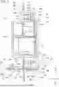


Sources:
- United States Patent and Trademark Office - verify current appl. status at the USPTO↗
Similar patent applications:
- » 20240016969
AIR CONDITIONER INDOOR UNIT, AIR CONDITIONER, AND PURIFICATION CONTROL METHOD OF AIR CONDITIONER INDOOR UNIT - » 20210325078
Door assembly for air conditioner indoor unit and air conditioner indoor unit having the same - » 20200158371
Air conditioner indoor unit, air conditioner control method, air conditioner and storage medium - » 20210356142
Air conditioner indoor unit, air conditioner, and method for controlling air conditioner - » 20200003433
Temperature-sensing bulb support for air-conditioner indoor unit, and air-conditioner indoor unit - » 20240159480
HEAT EXCHANGER MEMBER, HEAT EXCHANGER, AIR CONDITIONER INDOOR UNIT, AIR CONDITIONER OUTDOOR UNIT, AND REFRIGERATOR - » 20250362096
HEAT EXCHANGER MEMBER, HEAT EXCHANGER, AIR CONDITIONER INDOOR UNIT, AIR CONDITIONER OUTDOOR UNIT, AND REFRIGERATOR - » 20180149385
Water-receiving tray structure for indoor unit of air conditioner, indoor unit and air conditioner - » 20090248208
Indoor unit, air conditioner including indoor unit and method of controlling air conditioner - » 20080047281
Indoor unit, air conditioner including indoor unit and method of controlling air conditioner
Recent applications in this class:
- » 20260177279 2026-06-25
CONNECTION COMPONENT, HOUSING ASSEMBLY, AND AIR HANDLING UNIT - » 20260160442 2026-06-11
HUMIDIFIER - » 20260153264 2026-06-04
AIR CONDITIONING DEVICE FOR INSTALLATION CLOSE TO THE CEILING - » 20260139870 2026-05-21
Air Handling Unit Construction - » 20260139869 2026-05-21
HUMIDIFIER AND HUMIDIFYING AIR PURIFIER HAVING THE SAME - » 20260104176 2026-04-16
PORTABLE VENTILATION FAN ASSEMBLY - » 20260092722 2026-04-02
PACKAGING MEMBER AND PORTABLE AIR CONDITIONER - » 20260092721 2026-04-02
FRAMEWORK FOR AIR HANDLING UNIT - » 20260085855 2026-03-26
INDOOR UNIT OF AIR CONDITIONER - » 20260071777 2026-03-12
HVAC SYSTEM HAVING MODULAR COMPONENTS