ELECTRIC HEATING CABINET SECTION AND AIR HANDLING UNIT
US20260177282A1
2026-06-25
18/726,936
2023-06-02
Smart Summary: An electric heating cabinet has a special heating part and a main body. The heating part connects to a terminal block and has a piece that helps it stay in place. The main body has an opening and several spots inside where the heating part can fit. The heating part can slide into the main body through the opening. Once inside, it locks into place with the help of the positioning pieces. 🚀 TL;DR
Abstract:
An electric heating cabinet section includes a heating assembly and a cabinet body. The heating assembly includes a terminal block and a heating unit connected to the terminal block, and the heating unit includes a first positioning member provided at an end of the heating unit away from the terminal block. The cabinet body is provided with an opening in a circumferential wall surface of the cabinet body, and includes a plurality of second positioning members arranged at intervals on an inner wall of the cabinet body facing the opening. The heating unit is configured to move into an inner cavity of the cabinet body through the opening. The first positioning member is configured to fit in position with one of the second positioning members.
Inventors:
- Zhigang XING 34 🇨🇳 Foshan, China
- Qinghui LIN 2 🇨🇳 Foshan, China
- Haitao MIAO 2 🇨🇳 Foshan, China
Applicant:
Interested in similar patents?
Get notified when new applications in this technology area are published.
Classification:
F24H3/0411 » CPC main
Air heaters with forced circulation the air being in direct contact with the heating medium, e.g. electric heating element using electric energy supply, e.g. the heating medium being a resistive element; Heating by direct contact, i.e. with resistive elements, electrodes and fins being bonded together without additional element in-between for domestic or space-heating systems
F24H2250/02 » CPC further
Electrical heat generating means Resistances
F24H3/04 IPC
Air heaters with forced circulation the air being in direct contact with the heating medium, e.g. electric heating element
Description
CROSS-REFERENCES TO RELATED APPLICATION
The present application claims priority to Chinese Application No. 202310387102.2, filed on Apr. 11, 2023 and entitled “ELECTRIC HEATING CABINET SECTION AND AIR HANDLING UNIT,” the entire contents of which are incorporated herein by reference.
TECHNICAL FIELD
The present disclosure relates to the technical field of air conditioning equipment, and in particular to an electric heating cabinet section and an air handling unit.
BACKGROUND
In order to facilitate the maintenance of the air handling unit, a detachable heating assembly is installed in its box body. Due to the obstruction of the air duct at the air outlet of the air handling unit, after-sales personnel need to perform blind installation when maintaining the heating assembly. Moreover, the positioning components of the heating assembly have problems such as deformation and inaccurate installation guidance, making it difficult to install the heating assembly in place and the work efficiency is reduced.
SUMMARY
The present disclosure aims to at least partially solve one of the technical problems existing in the related art. To this end, according to the present disclosure, an electric heating cabinet section is proposed, which can make the installation and positioning of the heating assembly more convenient and improve the maintenance efficiency of the product.
The present disclosure also provides an air handling unit including the electric heating cabinet section described above.
According to an embodiment of the first aspect of the present disclosure, the electric heating cabinet section includes a heating assembly and a cabinet body. The heating assembly includes a terminal block and a heating unit connected to the terminal block. A first positioning member is provided at an end of the heating unit away from the terminal block. The cabinet body is provided with an opening in a circumferential wall surface of the cabinet body. Multiple second positioning members are provided in the cabinet body and arranged at intervals on an inner wall of the cabinet body facing the opening. The heating unit is capable of moving into an inner cavity of the cabinet body through the opening, and the first positioning member is capable of fitting in position with one of the second positioning members.
According to the embodiment of the present disclosure, the electric heating cabinet section has at least the following beneficial effects.
The heating unit is connected to the terminal block, can be moved into or out of an inner cavity of the cabinet body through the opening, and is provided with a first positioning member at an end away from the terminal block. In addition, the multiple second positioning members are arranged in the cabinet body. The multiple second positioning members are arranged at intervals on the inner wall of the cabinet body facing the opening. When the heating unit moves into the inner cavity of the cabinet body through the opening, the first positioning member is capable of fitting in position with one of the second positioning members to enable the heating unit to be positioned at any one of second positioning members, such that the positioning can be achieved without precise guidance, thereby facilitating the rapid installation of the heating assembly. The electric heating cabinet section of the embodiment is suitable for the air handling unit, which effectively improves the maintenance efficiency of the air handling unit.
According to some embodiments of the present disclosure, the heating unit includes a bracket and a heating body fixed at the bracket. One end of the bracket is connected to the terminal block, and the first positioning member is formed at the other end of the bracket away from the terminal block. The inner wall is provided with a fixation frame, and the second positioning members are formed at a side of the fixation frame facing the opening.
According to some embodiments of the present disclosure, the bracket includes multiple support rods arranged at intervals. The first positioning member is a connection rod connecting the support rods, the second positioning members are slots, and the connection rod is snapped into the slots along a height direction of the cabinet body.
According to some embodiments of the present disclosure, the connection rod is arranged along a first direction, the multiple slots are arranged at intervals on the fixation frame along a second direction, and the first direction and the second direction are perpendicular to each other.
According to some embodiments of the present disclosure, the fixation frame includes at least two side plates. The at least two side plates are arranged at intervals along a width direction of the cabinet body. The multiple slots are arranged at intervals on the side plates along the height direction of the cabinet body. The slots are arranged in one-to-one correspondence on the adjacent side plates to enable the connection rod to be capable of being snapped on all of the side plates.
According to some embodiments of the present disclosure, a tooth member is formed between the adjacent slots on the side plates. The tooth member is respectively provided with a bevel edge on both sides along the height direction of the cabinet body, and the bevel edges of the adjacent tooth members are shaped to form a first introduction port communicated with the slots.
According to some embodiments of the present disclosure, the multiple heating units are arranged, each of the heating units is provided with the connection rod, and the number of the slots is greater than the number of the connection rods.
According to some embodiments of the present disclosure, the connection rod or the support rod is provided with a limit member extending towards the adjacent brackets, and the adjacent brackets are capable of abutting against each other by the limit member.
According to some embodiments of the present disclosure, a first guide member is provided at the terminal block, a second guide member is provided in the cabinet body, and the second guide member is in sliding connection with the first guide member.
According to some embodiments of the present disclosure, the first guide member includes a folding edge formed at each side of a bottom end of the terminal block, the cabinet body includes a bottom plate, the second guide member includes two guide grooves formed at the bottom plate, and the folding edge is in sliding fit with the guide grooves. The folding edge includes at least two bending segments connected in sequence, the bottom plate is provided with a limit plate, the limit plate and a surface of the bottom plate together form the guide grooves, the notches of the two guide grooves are arranged oppositely, and the bending segments abut against inner walls of the guide grooves.
According to some embodiments of the present disclosure, one end of the limit plate away from the opening is provided with a turning edge, and the turning edge is bent towards an outer side of the guide groove to form a second introduction port at an end of the guide groove.
According to some embodiments of the present disclosure, an outer wall surface of the terminal block is provided with an opening hole arranged along the height direction of the terminal block.
According to an embodiment of the second aspect of the present disclosure, the air handling unit includes the electric heating cabinet section described in the embodiment of the first aspect. According to an embodiment of the present disclosure, the air handling unit has at least the following beneficial effects.
The air handling unit uses the electric heating cabinet section of the embodiment for heating, and the heating unit is capable of moving into or out of an inner cavity of the cabinet body through the opening. When the heating unit moves into the inner cavity of the cabinet body through the opening, the first positioning member is capable of fitting in position with one of the second positioning members to enable the heating unit to be positioned at any one of second positioning members, such that the positioning can be achieved without precise guidance, thereby facilitating the rapid installation of the heating assembly. The electric heating cabinet section of the embodiment is suitable for the air handling unit, which effectively improves the maintenance efficiency of the air handling unit.
Additional features and advantages of the present disclosure will be set forth in the following description and in part will be apparent from the description, or may be learned by implementing the present disclosure.
BRIEF DESCRIPTION OF DRAWINGS
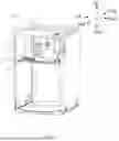
FIG. 1 is a schematic structural diagram of a fan box according to an embodiment of the present disclosure, showing various structures inside the fan box;
FIG. 2 is a schematic structural diagram of an electric heating cabinet section according to an embodiment of the present disclosure;
FIG. 3 is a schematic structural diagram of a heating assembly installed on a partition according to an embodiment of the present disclosure;
FIG. 4 is an enlarged structural schematic diagram of portion A in FIG. 2;
FIG. 5 is an enlarged structural schematic diagram of portion B in FIG. 3;
FIG. 6 is a schematic structural diagram of a fixation frame according to an embodiment of the present disclosure;
FIG. 7 is a schematic structural diagram of a fixation frame according to another embodiment of the present disclosure;
FIG. 8 is a schematic structural diagram of a fixation frame according to yet another embodiment of the present disclosure;
FIG. 9 is a schematic structural diagram of a bracket according to an embodiment of the present disclosure; and
FIG. 10 is a schematic structural diagram of a bracket according to another embodiment of the present disclosure.
Reference numerals for the accompanying drawings:
-
- fan box 1000;
- electric heating cabinet section 2000;
- box body 100; window 110; air outlet 120; upper cavity 130; lower cavity 140;
- heating assembly 200; heating unit 210; heating wire 211; bracket 212; support rod 2121; connection rod 2122; limit member 2123; first positioning member 213; insulating member 214; terminal block 220; electrical component 221; opening hole 222; convex edge 223; rear side plate 224; first guide member 230; folding edge 231; first bending segment 2311; second bending segment 2312;
cabinet body 300; air duct 301; front baffle 310; bottom plate 320; second guide member 330; limit plate 331; turning edge 3311; guide groove 332;
fixation frame 400; second positioning member 401; side plate 410; slot 411; tooth member 412; bevel edge 4121; first introduction port 413; fixation plate 420.
DETAILED DESCRIPTION
Embodiments of the present disclosure are described in detail below, examples of which are illustrated in the accompanying drawings, where the same or similar reference numerals throughout represent the same or similar elements or elements with the same or similar functions. The embodiments described below with reference to the accompanying drawings are exemplary and are only used to explain the present disclosure and cannot be understood as limiting the present disclosure.
In the description of the present disclosure, it should be understood that the orientation or positional relationship indicated by the terms “upper,” “lower,” etc. is based on the orientation or positional relationship shown in the accompanying drawings, and is only for the convenience of describing the present disclosure and simplifying the description, rather than indicating or implying that the device or element referred to must have a specific orientation, be constructed, and operated in a specific orientation, and therefore cannot to be construed as a limitation of the present disclosure.
In the description of the present disclosure, if the terms “first” and “second” are described, they are only used for the purpose of distinguishing technical features, and cannot be understood as indicating or implying the relative importance, implicitly indicating the number of the indicated technical features or implicitly indicating the sequence relationship of the indicated technical features.
In the description of the present disclosure, it should be noted that words such as “arranged,” “installed” and “connected” should be understood in a broad sense. Those skilled in the art may reasonably determine the specific meaning of the above words in the present disclosure in combination with the specific content of the technical solution.
In the description of the present disclosure, the description of some embodiments, specific embodiments, etc. means that specific features, structures, materials or characteristics described in combination with the embodiment or example are included in at least one embodiment or example of the present disclosure. In this description, schematic representations of the above terms do not necessarily refer to the same implementation or example. Furthermore, the specific features, structures, materials or characteristics described may be combined in any suitable manner in any one or more embodiments or examples.
The technical solution of the present disclosure will be clearly and completely described below with reference to the accompanying drawings. Obviously, the embodiments described below are some, but not all, of the embodiments of the present disclosure.
The air handling unit may also be called an American air duct machine. According to an embodiment of the present disclosure, the air handling unit includes a fan box 1000 and a heat exchange box, where a fan assembly and an electric heating cabinet section 2000 are installed inside the fan box 1000. An auxiliary heating can be realized by the heating assembly 200. A heat exchange assembly is installed in the heat exchange box. The fan box 1000 and the heat exchange box are connected in a detachable installation, which facilitates after-sales personnel to install even in a narrow space and improves installation efficiency. It can be understood that the air handling unit may also adopt an integral design, that is, the electric heating cabinet section 2000, the heat exchange assembly and the fan assembly are installed inside the same box body.
In order to facilitate the maintenance of the heating assembly 200, the heating assembly 200 is detachably installed in the box body 100. The heating assembly 200 is generally an optional accessory, that is, the heating assembly 200 may not be installed when leaving the factory. When the user chooses to have one, he needs to purchase the heating assembly 200 and have after-sales personnel come to install the heating assembly 200. However, after the air handling unit is installed, the air outlet 120 has been connected to an air duct. Due to the obstruction of the air duct, after-sales personnel need to blindly install the heating assembly 200 when it needs maintain. The heating assembly 200 may be difficult to be installed in place due to deformation of the components or the inability of the installation guide to accurately limit the position, thereby reducing the work efficiency.
In order to solve the above problem, according to an embodiment of the present disclosure, the electric heating cabinet section 2000 is provided. The electric heating cabinet section 2000 is installed in the fan box 1000. The electric heating cabinet section 2000 will be described in detail below using the fan box 1000 as an example.
Referring to FIG. 1, according to an embodiment of the present disclosure, the fan box 1000 includes a box body 100. A front side of the box body 100 is provided with a window 110 and a panel. The panel is detachably connected to the window 110. An air outlet 120 is arranged on an upper end of box body 100. The electric heating cabinet section 2000 and the fan assembly are installed in the box body 100, where the electric heating cabinet section 2000 is arranged in proximity to the air outlet 120, and the fan assembly is installed below the electric heating cabinet section 2000. The electric heating cabinet section 2000 may be used to heat the air flow in the air duct 301 to generate hot wind, and the hot wind is blown out from the air outlet 120 to play the role of electric auxiliary heating. The structure of the panel and fan assembly is not shown in FIG. 1.
Referring to FIGS. 1 and 2, according to an embodiment of the present disclosure, the electric heating cabinet section 2000 includes a heating assembly 200 and a cabinet body 300. The electric heating cabinet section 2000 is fixedly connected to the box body 100 with the cabinet body 300. The upper and lower surfaces of the cabinet body 300 are open to form an air duct 301 communicated with the air outlet 120. The heating assembly 200 is detachably installed in the cabinet body 300. It can be understood that when the heating assembly 200 needs to be installed or inspected, the panel can be opened and the heating assembly 200 may be taken out or put in through the window 110 without removing the fan box 1000 and the heat exchange box, enabling an easy and convenient operation.
Referring to FIGS. 2 and 3, according to an embodiment of the present disclosure, the heating assembly 200 includes a terminal block 220 and a heating unit 210. The front side of the terminal block 220 faces the window 110. The heating unit 210 is connected to the rear side of the terminal block 220. The terminal block 220 is configured to install an electrical component 221 such as a switch, a wiring terminal or a circuit breaker, and to provide power to the heating unit 210. The cabinet body 300 is provided with an opening at a front side wall surface thereof. During the process of installation, the heating unit 210 may be put into the cabinet body 300 through the opening by pushing the terminal block 220. The heating unit 210 may also be moved out of the cabinet body 300 through the opening to realize the detachable installation of the heating assembly 200. It can be understood that after being installed in place, the heating unit 210 is located in an inner cavity of the cabinet body 300, and the terminal block 220 is located outside of the cabinet body 300, thereby achieving isolation between the heating unit 210 and the electrical component 221, and safety requirements are met.
Referring to FIG. 2, it can be understood that in an embodiment, a first guide member 230 is provided at the terminal block 220, and a second guide member 330 is provided at the cabinet body 300. The first guide member 230 is in sliding connection with the second guide member 330. In addition, each of the first guide member 230 and the second guide member 330 is arranged along a direction from a front end to a rear end of the box body 100. With the cooperation of the first guide member 230 and the second guide member 330, the heating unit 210 can be quickly moved into or out of the cabinet body 300. This arrangement is stable and reliable.
It should be noted that, as shown in FIG. 1, the bottom of the cabinet body 300 is provided with a bottom plate 320. The bottom plate 320 separates the inner cavity of the box body 100 to form an upper chamber and a lower chamber. The bottom plate 320 may also be understood as a partition, where the heating assembly 200 is located in the upper chamber, and the fan assembly is located in the lower chamber. It can be understood that the bottom plate 320 is fixedly connected with the box body 100, and the heating assembly 200 can be supported by the bottom plate 320. The second guide member 330 is disposed on the bottom plate 320. The first guide member 230 and the second guide member 330 may be guide rails or other guiding structures. For example, the bottom of the terminal block 220 and the upper surface of the bottom plate 320 are respectively provided with a guide rail that is matched, where the guide rail on the bottom plate 320 extends from the window 110 to the opening, and the terminal block 220 can move between the window 110 and the opening along the guidance of the guide rails, enabling the heating unit 210 to be pushed into or pulled out of the cabinet body 300.
In an embodiment, the first guide member 230 may be disposed on a side of the terminal block 220, and the second guide member 330 may be disposed on the inner wall of the box body 100, for example, the guide rails are disposed on a side wall of the terminal block 220 and an opposite side wall of the box body 100, thus the heating assembly 200 can be guided.
In the related art, when there is no guide structure, it is inconvenient to pull out the heating assembly 200, and when the heating assembly 200 is inserted to be installed, it is easy to cause inaccurate positioning, which reduces the installation efficiency. In addition, if the installation is not in place, it is easy to cause the air handling unit to vibrate during operation, which will further generate noise and affect user experience.
It can be understood that in the embodiment of the present disclosure, the heating assembly 200 is guided by the cooperation of the first guide member 230 and the second guide member 330, which can make the heating assembly 200 less likely to deflect during the process of installation and make removal more convenient, thereby reducing the possibility of vibration noise caused by the heating assembly 200 being deflected during operation of the air handling unit, and making the structure more stable and reliable.
Referring to FIGS. 2 and 4, in some embodiments, the first guide member 230 includes folding edges 231 formed at each side of the bottom end of the terminal block 220, and each of the folding edges 231 is arranged extending along a direction from front to rear of the terminal block 220. The second guide member 330 includes two guide grooves 332 formed at the bottom plate 320. The two folding edges 231 are arranged in one-to-one correspondence with the two guide grooves 332. The folding edges 231 are capable of sliding along the guide grooves 332, such that a guiding function can be provided for the terminal block 220 by the folding edges 231 being in sliding fit with the guide grooves 332.
As shown in FIG. 4, it can be understood that in an embodiment, the terminal block 220 and the bottom plate 320 may be made of sheet metal parts, and the sheet metal parts may be bent to form the folding edges 231 at the bottom of the terminal block 220. The bottom plate 320 may be stamped to have the guide grooves 332. The notches of the two guide grooves 332 both face the terminal block 220, and the notches of the two guide grooves 332 are arranged oppositely. The terminal block 220 is located between the two guide grooves 332, such that the folding edges 231 of two sides can be correspondingly inserted into the guide grooves 332 and slide along the guide grooves 332.
In an embodiment, the folding edges 231 may be disposed towards the bottom plate 320, and the notches of the guide grooves 332 may be disposed upwards, such that the two folding edges 231 can be inserted downwards into the corresponding guide grooves 332 for matching. In some embodiments, the number of folding edges 231 and guide grooves 332 are not limited to two. That is, two or more folding edges 231 may also be disposed on each side of the terminal block 220, and meanwhile two or more folding edges 231 are disposed on the bottom plate 320 correspondingly. A more stable guide structure is achieved by the cooperation of the folding edges 231 and the guide grooves 332.
Referring to FIG. 4, in an embodiment, each folding edge 231 includes two bending segments connected in sequence. The bottom plate 320 is provided with two limit plates 331. Each limit plate 331 cooperates with an upper surface of the bottom plate 320 to form a guide groove 332. The folding edge 231 and the guide groove 332 on the right side are taken as an example for illustration. The folding edge 231 includes a first bending segment 2311 and a second bending segment 2312. The bending angle between the first bending segment 2311 and the second bending segment 2312 is substantially 90°, such that the two bending segments are connected in sequence to form a structure with a substantially U-shaped cross-section. One end of the limit plate 331 is fixedly connected to the bottom plate 320, and the other end is spaced from the bottom plate 320 to form a guide groove 332 with a substantially U-shaped cross-section. The folding edge 231 and the guide groove 332 are in clearance fit, thereby ensuring that the folding edge 231 can be in sliding connection with the guide groove 332.
It can be understood that the folding edge 231 and the guide groove 332 use the arrangement of the embodiment shown in FIG. 4. When the folding edge 231 slides along the guide groove 332, each of the first bending segment 2311 and the second bending segment 2312 is capable of abutting against the inner wall of the guide groove 332, playing a limiting role. Specifically, the top and bottom walls of the guide groove 332 are capable of limiting the folding edge 231 in the vertical direction, and the side wall of the guide groove 332 is capable of limiting the folding edge 231 in the horizontal direction. At the same time, the two guide grooves 332 are cooperated to limit the left and right sides of the terminal block 220, such that the heating assembly 200 is limited by four directions, up, down, left, and right, thereby achieving a more stable installation and guiding effect. No matter what install position the air handling unit is adopt, vertical, horizontal or upside down, it can be ensured that the heating assembly 200 will not easily to shake or fall, and the structure will be more stable and reliable.
It should be noted that the number of bending segments is not limited to two, and more bending segments may also be disposed. For example, three bending segments are connected in sequence to form a folding edge 231 with a substantially square-shaped cross-section. Of course, the cross-sectional shape of the folding edge 231 may also be a cylindrical, triangular or other polygonal shape, without specific definition.
Referring to FIG. 4, the limit plate 331 includes an upper baffle and a side baffle. The upper baffle and the side baffle cooperate with the upper surface of the bottom plate 320 to form a guide groove 332. The upper baffle plate and the side baffle plate are respectively provided with a turning edge 3311 at one end facing the window 110. The turning edge 3311 is bent and disposed obliquely towards the outer side of the guide groove 332, such that the two turning edges 3311 form a guide bevel towards the end face of the window 110. The second introduction port is formed at the front end of the guide groove 332 by matching the guide bevel, and serves as a guide member, which facilitates the folding edge 231 to enter the guide groove 332 along the second introduction port, thereby achieving rapid positioning of the folding edge 231 and the guide groove 332.
Referring to FIG. 2, it can be understood that manual operation is required when removing and installing the heating assembly 200. Thus, in an embodiment, the side wall of the terminal block 220 is provided with an opening hole 222. The opening hole 222 is disposed along the height direction of the terminal block 220, and is substantially in a long and narrow shape. The specific size of the opening hole 222 allows human hands to access, thereby making it easy to grasp the heating assembly 200 for removal and installation without the need for additional handles, simplifying the structure of the heating assembly 200, and being conducive to saving installation space. In an embodiment, it can be understood that the opening hole 222 may be disposed on each side of the terminal block 220, or the opening hole 222 may be disposed on the top wall surface of the terminal block 220. The specific arrangement is based on application requirements without specific definition.
Referring to FIGS. 2 and 3, in some embodiments, a convex edge 223 is disposed on each side of the terminal block 220, and an opening is disposed in a front baffle 310 of the cabinet body 300. The convex edge 223 and the front baffle 310 are respectively provided with corresponding screw holes. When the heating assembly 200 is installed in place, the terminal block 220 is fixedly connected with the cabinet body 300 by screwing the screws into the screw holes, thereby achieving the object of fixing the heating assembly 200 and preventing the heating assembly 200 from loosening and falling.
Considering that the heating unit 210 needs to be positioned within the cabinet body 300, in the related art, the heating assembly 200 is positioned using an installation method of shafts being inserted in holes. In this method, mounting holes are reserved on the cabinet body 300, and steel wire shafts are disposed on the heating unit 210, thus multiple steel wire shafts need to be inserted into the corresponding mounting holes at the same time to install them in place. After the air handling unit is installed, due to the obstruction of the air duct, after-sales personnel need to perform blind installation when aligning the steel wire shaft with the mounting hole. However, the heating assembly 200 may be difficult to be installed in place due to the deformation of the steel wire shaft or the inability of the installation guide to accurately limit the position, thereby reducing the work efficiency.
Referring to FIGS. 2 and 3, it can be understood that one end of the heating unit 210 is connected to the terminal block 220, the other end is provided with a first positioning member 213, and multiple second positioning members 401 are arranged in the cabinet body 300. The multiple second positioning members 401 are arranged at intervals on the inner wall of the cabinet body 300 facing the opening. The first positioning member 213 can fit with any one of second positioning members 401 for positioning. The second positioning members 401 are arranged adjacent to each other. When the terminal block 220 drives the heating unit 210 to move into the inner cavity of the cabinet body 300 through the opening, the first positioning member 213 will move towards the second positioning member 401. When the heating unit 210 is installed in place, the first positioning member 213 is capable of having location fit with one of the second positioning members 401 to enable the heating unit 210 to be quickly positioned.
It can be understood that, compared with the one-to-one positioning method in the related art, in the embodiment of the present disclosure, a one-to-many positioning method is used, that is, one first positioning member 213 may correspond to the multiple second positioning members 401. The number of the second positioning members 401 needs to be greater than the number of the first positioning members 213. For example, the first positioning member 213 may be a positioning rod, the second positioning member 401 may be a positioning groove, and multiple positioning grooves are arranged next to each other. When the positioning rod is deformed and deviated, it may be inserted into the adjacent positioning groove for positioning, thereby the positioning of the heating unit 210 is not affected, and positioning problems caused by component deformation or the inability of installation guide to accurately limit the position are effectively solved. In this way, rapid positioning can be achieved without the need for precise guidance, and the heating assembly 200 can be quickly installed in place even when it is blindly installed, effectively improving the maintenance efficiency of the air handling unit.
Referring to FIG. 3, according to the embodiment of the present disclosure, the heating unit 210 includes a bracket 212 and a heating body. The heating body is an electric heating wire 211. The electric heating wire 211 is spirally wound on the bracket 212. The bracket 212 is fixed to the heating wire 211 by the insulating member 214 to ensure the insulation performance of the heating unit 210. In an embodiment, the heating body is not limited to the spiral electric heating wire 211. Other forms of the heating body may also be used. For example, the heating body may be a heating sheet, a heating tube, etc.
It can be understood that the first positioning member 213 is formed at the end of the bracket 212 away from the terminal block 220, the inner wall of the cabinet body 300 is provided with a fixation frame 400, and the second positioning members 401 are formed at the side of the fixation frame 400 facing the opening, for example, the bracket 212 may be provided with a positioning rod at the end of the bracket 212, and the multiple positioning grooves may be disposed on the fixation frame 400 to facilitate processing and forming the second positioning members 401 on the cabinet body 300.
Referring to FIGS. 3 and 5, in some embodiments, the bracket 212 includes multiple support rods 2121 arranged at intervals. The multiple support rods 2121 are connected on a connection rod 2122. The connection rods 2122 are located at the end of the bracket 212, and are used as the first positioning member 213. Multiple slots 411 are arranged on the fixation frame 400, and the slots 411 are used as the second positioning members 401. It can be understood that in the embodiment, the multiple support rods 2121 are arranged at intervals along a left-right direction of the terminal block 220, and the connection rods 2122 extend along the left-right direction, such that the connection rod 2122 can connect the multiple support rods 2121 at the same time, and the multiple slots 411 are distributed on the fixation frame 400 in an up-down direction, where the left-right direction is a first direction, and the up-down direction is a second direction. The connection rods 2122 can be snapped into the slots 411 in a direction perpendicular to the length thereof.
It can be understood from FIG. 5 that the multiple slots 411 are arranged at intervals along the vertical direction of the fixation frame 400, and the connection rod 2122 is laterally snapped into the slot 411. When the bracket 212 is deformed or the guide accuracy is not high, the connection rod 2122 may be snapped into the adjacent slot 411 to facilitate positioning of the bracket 212, thereby achieving the object of positioning the heating unit 210.
It should be noted that the support rods 2121 may be arranged at intervals along the vertical direction, such that the connection rods 2122 may be arranged extending along the vertical direction. Correspondingly, the slots 411 are arranged at intervals along the horizontal direction, such that the connection rod 2122 can be snapped into the slots 411. The first and the second directions are specifically set according to the actual orientation without specific definition. In the embodiment, the spacing distance between adjacent slots 411 may be set to 4 mm. In other embodiment, the spacing distance may also be 3 mm, 5 mm, etc.
Referring to FIG. 3, in an embodiment of the present disclosure, the heating assembly 200 is provided with four heating units 210 that are arranged at intervals in the up-down direction. Each heating unit 210 is respectively provided with a bracket 212 and an electric heating wire 211. In other embodiment, the number of heating units 210 is not limited to four. It can also be three, five or more. The specific number of the heating units 210 is selected according to the application requirements. Through the combination of the multiple heating units 210, the heating power of the heating assembly 200 can be increased, thus improving the heating efficiency.
Referring to FIG. 3, it can be understood that each heating unit 210 is provided with a connection rod 2122, and multiple slots 411 are arranged at intervals along the height direction of the fixation frame 400, and the number of slots 411 is greater than the number of connection rods 2122, such that each heating unit 210 may be correspondingly fastened in the adjacent slots 411 with the connection rods 2122, so as to avoid the situation that the connection rods 2122 are not snapped in place. As shown in the embodiment shown in FIG. 3, twelve slots 411 are provided along the height direction. The upper heating unit 210 is taken as an example for illustration. When the heating unit 210 is close to the fixation frame 400, the connection rod 2122 may be snapped into the first slot 411, the second slot 411 or the third slot 411 on the upper end of the fixer 400 to facilitate the connection rod 2122 to be snapped into the adjacent slots 411 when it is deflected, so as to meet the requirement of rapid positioning.
Referring to FIG. 3 and FIG. 5, it can be understood that a tooth member 412 is formed between adjacent slots 411 on the fixation frame 400. The upper and lower sides of the tooth member 412 are provided with bevel edges 4121 respectively. The tooth member 412 and the slot 411 together form a zigzag structure, and the bevel edges 4121 of the adjacent tooth members 412 are shaped to form a first introduction port 413, which is communicated with the slot 411. The width of the first introduction port 413 gradually increases to facilitate the connection rods 2122 to be introduced into the slots 411 along the first introduction port 413, such that the connection rods 2122 may be quickly installed in place.
Referring to FIG. 3, it should be noted that in the embodiment, the fixation frame 400 includes two side plates 410 that are arranged at intervals along the width direction of the cabinet body 300. The side plates 410 are fixedly mounted on the inner wall of the cabinet body 300. Each side plate 410 is provided with multiple slots 411 that are arranged at intervals along the length direction of the side plate 410. The length direction of the side plates 410 is consistent with the height direction of the cabinet body 300. The slots 411 on adjacent side plates 410 are arranged in one-to-one correspondence, that is, the number of the slots 411 on one side plates 410 is the same as the other, and the two slots 411 at the same height position are arranged corresponding to each other, such that the connection rod 2122 can be fixed at the two side plates 410 at the same time, making the snap-in structure more stable and reliable.
It can be understood from FIG. 2 that the width direction of the cabinet body 300 is the left-right direction shown in FIG. 2, and the height direction of the cabinet body 300 is the up-down direction shown in FIG. 2.
It can be understood from FIG. 6 that in some embodiments, the two side plates 410 are separated by a certain distance so that both ends of the connection rod 2122 can be supported. Supporting is more reliable and effectively prevents the heating unit 210 from loosening and falling. It should be noted that the distance between the two side plates 410 is selected according to the size requirements of the connection rod 2122 without specific definition.
FIG. 6 only shows one of the possible examples, and the number of the side plates 410 is not limited to two. As shown in FIG. 7, one side plate 410 is provided, and the installation position of the side plate 410 may be located in the middle of the inner wall, such that the middle of the connection rod 2122 can be snapped into the slot 411 to achieve the object of stably supporting the bracket 212. Of course, the number of the side plates 410 may also be set to three or more, which is selected specifically according to application requirements.
Referring to FIG. 8, in some embodiments, the two side plates 410 are connected through a fixation plate 420. The side plates 410 and the fixation plate 420 are an integrally-formed structure. Specifically, they can be formed by stamping a steel plate. In this way, it has higher structural strength and improve reliability of the positioning of the heating unit 210. In addition, installation is easy and convenient, which helps to improve installation efficiency.
It should be noted that the tooth member 412 and the slot 411 are processed to form on the side plate 410. Specifically, the tooth member 412 and the slot 411 may be formed by integral stamping of the side plate 410, and it is easy to implement the processing. In addition, in the embodiment, the side plate 410 is fixedly connected to the cabinet body 300 by screws, and the structure is stable and reliable. In an embodiment, the side plate 410 may also be fixed to the cabinet body 300 by riveting or welding.
In some embodiments, the material of the fixation frame 400 is not limited to steel plates, and may also be made of ceramics, cast aluminum, etc. In addition, the fixation frame 400 may also be formed by bending steel wires. Specifically, the steel wires are bent to form a zigzag structure to meet the requirement of being able to catch the connection rod 2122.
Referring to FIG. 9, in some embodiments, each of the two ends of the connection rod 2122 is provided with a bracket 212 extending towards the lower side to form a limit member 2123. The limit member 2123 can be understood as an extending segment by extending and bending both ends of the connection rod 2122. It can be understood that adjacent brackets 212 are arranged at intervals. One end of each bracket 212 is fixedly connected to the rear side plate 224 of the terminal block 220, and the end of each bracket 212 away from the terminal block 220 is limited through the limit member 2123. The limit member 2123 is capable of abutting against the adjacent brackets 212 to achieve the object of limiting, thereby ensuring that a certain distance is maintained between the brackets 212, and avoiding the risk of contact between the heating wires 211.
Referring to FIG. 10, in some embodiments, the limit member 2123 is arranged at the end of the support rod 2121, that is, the end of the support rod 2121 is bent to form an extending segment. The limit member 2123 is substantially L-shaped, such that the limit member 2123 is capable of abutting against the support rod 2121 of the adjacent brackets 212, and that the positions of the brackets 212 can be limited by the limit member 2123, thereby avoiding the risk of contact between the heating wires 211.
The embodiments of the present disclosure are described in detail above in combination with the accompanying drawings. However, the present disclosure is not limited to the above embodiments. Within the scope of knowledge possessed by those of ordinary skill in the art, various variations can be made without departing from the purpose of the present disclosure.
Claims
1-13. (canceled)
14. An electric heating cabinet section comprising:
a heating assembly, including a terminal block and a heating unit connected to the terminal block, and the heating unit including a first positioning member provided at an end of the heating unit away from the terminal block; and
a cabinet body, provided with an opening in a circumferential wall surface of the cabinet body, the cabinet body including a plurality of second positioning members arranged at intervals on an inner wall of the cabinet body facing the opening;
wherein:
the heating unit is configured to move into an inner cavity of the cabinet body through the opening; and
the first positioning member is configured to fit in position with one of the second positioning members.
15. The electric heating cabinet section of claim 14, wherein:
the heating unit includes a bracket and a heating body fixed on the bracket;
one end of the bracket is connected to the terminal block, and the first positioning member is formed at another end of the bracket away from the terminal block; and
the inner wall includes a fixation frame, and the second positioning members are formed at a side of the fixation frame facing the opening.
16. The electric heating cabinet section of claim 15, wherein:
the bracket includes a plurality of support rods arranged at intervals;
the first positioning member includes a connection rod connecting the support rods;
the second positioning members include slots; and
the connection rod is configured to be snapped into the slots along a height direction of the cabinet body.
17. The electric heating cabinet section of claim 16, wherein the connection rod is arranged along a first direction, the slots are arranged at intervals on the fixation frame along a second direction, and the first direction and the second direction are perpendicular to each other.
18. The electric heating cabinet section of claim 16, wherein:
the fixation frame includes at least two side plates arranged at intervals along a width direction of the cabinet body;
the slots are arranged at intervals on the side plates along the height direction of the cabinet body; and
the slots on adjacent ones of the side plates are arranged in one-to-one correspondence to enable the connection rod to be capable of being snapped to all of the side plates.
19. The electric heating cabinet section of claim 18, wherein a tooth member is formed between adjacent ones of the slots on the side plates, a bevel edge is provided on each of two sides of the tooth member along the height direction of the cabinet body, and the bevel edges of adjacent ones of the tooth members are shaped to form an introduction port communicated with the slots.
20. The electric heating cabinet section of claim 16, wherein:
the heating unit is one of a plurality of heating units of the electric heating cabinet section, and the connection rod is one of a plurality of connection rods each provided at one of the heating units; and
a number of the slots is greater than a number of the connection rods.
21. The electric heating cabinet section of claim 16, wherein the connection rod or one of the support rods is provided with a limit member extending towards adjacent ones of the brackets, and the adjacent ones of the brackets are configured to abut against each other through the limit member.
22. The electric heating cabinet section of claim 14, wherein a first guide member is provided at the terminal block, a second guide member is provided in the cabinet body, and the second guide member is in sliding connection with the first guide member.
23. The electric heating cabinet section of claim 22, wherein:
the first guide member includes a folding edge at each side of a bottom end of the terminal block;
the cabinet body includes a bottom plate;
the second guide member includes two guide grooves formed at the bottom plate;
the folding edge is in sliding fit with the guide grooves, and includes at least two bending segments connected in sequence;
the bottom plate is provided with a limit plate, the limit plate and a surface of the bottom plate together form the guide grooves, notches of the two guide grooves are arranged oppositely, and the bending segments abut against inner walls of the guide grooves.
24. The electric heating cabinet section of claim 23, wherein one end of the limit plate away from the opening is provided with a turning edge, and the turning edge is bent towards an outer side of the guide groove to form an introduction port at an end of the guide groove.
25. The electric heating cabinet section of claim 14, wherein an outer wall surface of the terminal block is provided with an opening hole arranged along a height direction of the terminal block.
26. An air handling unit comprising:
an electric heating cabinet section including.
a heating assembly, including a terminal block and a heating unit connected to the terminal block, and the heating unit including a first positioning member provided at an end of the heating unit away from the terminal block; and
a cabinet body, provided with an opening in a circumferential wall surface of the cabinet body, the cabinet body including a plurality of second positioning members arranged at intervals on an inner wall of the cabinet body facing the opening;
wherein:
the heating unit is configured to move into an inner cavity of the cabinet body through the opening; and
the first positioning member is configured to fit in position with one of the second positioning members.
27. The air handling unit of claim 26, wherein:
the heating unit includes a bracket and a heating body fixed on the bracket;
one end of the bracket is connected to the terminal block, and the first positioning member is formed at another end of the bracket away from the terminal block; and
the inner wall includes a fixation frame, and the second positioning members are formed at a side of the fixation frame facing the opening.
28. The air handling unit of claim 27, wherein:
the bracket includes a plurality of support rods arranged at intervals;
the first positioning member includes a connection rod connecting the support rods;
the second positioning members include slots; and
the connection rod is configured to be snapped into the slots along a height direction of the cabinet body.
29. The air handling unit of claim 28, wherein the connection rod is arranged along a first direction, the slots are arranged at intervals on the fixation frame along a second direction, and the first direction and the second direction are perpendicular to each other.
30. The air handling unit of claim 28, wherein:
the fixation frame includes at least two side plates arranged at intervals along a width direction of the cabinet body;
the slots are arranged at intervals on the side plates along the height direction of the cabinet body; and
the slots on adjacent ones of the side plates are arranged in one-to-one correspondence to enable the connection rod to be capable of being snapped to all of the side plates.
31. The air handling unit of claim 30, wherein a tooth member is formed between adjacent ones of the slots on the side plates, a bevel edge is provided on each of two sides of the tooth member along the height direction of the cabinet body, and the bevel edges of adjacent ones of the tooth members are shaped to form an introduction port communicated with the slots.
32. The air handling unit of claim 28, wherein:
the heating unit is one of a plurality of heating units of the electric heating cabinet section, and the connection rod is one of a plurality of connection rods each provided at one of the heating units; and
a number of the slots is greater than a number of the connection rods.
33. The air handling unit of claim 28, wherein the connection rod or one of the support rods is provided with a limit member extending towards adjacent ones of the brackets, and the adjacent ones of the brackets are configured to abut against each other through the limit member.
Images & Drawings included:


Sources:
- United States Patent and Trademark Office - verify current appl. status at the USPTO↗
Recent applications in this class:
- » 20240426515 2024-12-26
Heated Ceiling Fan Device - » 20240255180 2024-08-01
CONVECTION BATHROOM HEATING SYSTEM - » 20220154975 2022-05-19
Electric heater - » 20210333014 2021-10-28
Air control method for air handler unit - » 20200191434 2020-06-18
Convection fan cover - » 20200056808 2020-02-20
HEATER FOR HEATING A SPACE - » 20160245549 2016-08-25
LYONS FURNACE SYSTEM - » 20160231020 2016-08-11
Integrated heating and blowing arrangement for heater machine - » 20160209078 2016-07-21
Heating device - » 20150125134 2015-05-07
HEAT-RESISTANT ELECTRIC HEATER