METHODS OF OPERATING A WATER HEATER APPLIANCE
US20260177286A1
2026-06-25
18/990,060
2024-12-20
Smart Summary: A water heater has a tank and a mixing valve to control water temperature. It uses temperature sensors to check how hot the water is in a connected pipe. The heater measures this temperature to ensure it's at the right level. If the water temperature is not where it should be, a recirculation pump is turned on to help adjust it. This process helps provide hot water more efficiently. 🚀 TL;DR
Abstract:
A water heater appliance includes a tank and a mixing valve. A method of operating the water heater appliance includes receiving temperature sensor data indicative of a water temperature within a water conduit fluidly coupled to the tank. Additionally, the method includes measuring the water temperature within the water conduit based on the received temperature sensor data. Furthermore, the method includes operating a recirculation pump based on the measured water temperature within the water conduit.
Inventors:
- Alan George Constance 9 🇺🇸 Jeffersonville, IN, United States
- Paul Goodjohn 26 🇺🇸 Crestwood, KY, United States
- Gregory L. Hutchison 9 🇺🇸 Shelbyville, KY, United States
Applicant:
Interested in similar patents?
Get notified when new applications in this technology area are published.
Classification:
F24H15/174 » CPC main
Control of fluid heaters characterised by the purpose of the control Supplying heated water with desired temperature or desired range of temperature
F24D17/0078 » CPC further
Domestic hot-water supply systems Recirculation systems
F24H15/215 » CPC further
Control of fluid heaters characterised by control inputs; Temperature of the water before heating
F24H15/223 » CPC further
Control of fluid heaters characterised by control inputs; Temperature of the water in the water storage tank
F24H15/315 » CPC further
Control of fluid heaters characterised by control outputs; characterised by the components to be controlled; Control of valves of mixing valves
F24H15/335 » CPC further
Control of fluid heaters characterised by control outputs; characterised by the components to be controlled Control of pumps, e.g. on-off control
F24D17/00 IPC
Domestic hot-water supply systems
Description
FIELD OF THE INVENTION
The present subject matter relates generally to water heater appliances and methods for operating water heater appliances.
BACKGROUND OF THE INVENTION
Certain water heater appliances include a tank therein. Heating elements, such as gas burners, electric resistance elements, or induction elements, heat water within the tank during operation of such water heater appliances. In particular, the heating elements generally heat water within the tank to a predetermined temperature. The predetermined temperature is generally selected such that heated water within the tank is suitable for showering, washing hands, etc.
During operation, relatively cool water flows into the tank, and the heating elements operate to heat such water to the predetermined temperature. Thus, the volume of heated water available at the predetermined temperature is generally limited to the volume of the tank. Additionally, the volume of heated water available at the predetermined temperature may be less than the total volume of the tank, e.g., after a large draw or several draws in close succession, while the tank is recovering, e.g., heating the relatively cool water which flowed in to replace the hot water drawn out.
During such recovery time, operability of the water heater may be limited. For example, a user wishing to take a long, hot shower or to wash a large load of laundry may not have a sufficient volume of heated water available at the predetermined temperature to satisfactorily complete such tasks.
As such, a mixing valve may be utilized to mix heated water and relatively cool water for supplying to a user. Additionally, recirculation conduit or piping and a pump may be utilized to recirculate unused water. However, the recirculation conduit and pump pose issues to the water heater appliance when used in combination with the mixing valve.
Accordingly, methods for operating a water heater appliance to conserve the available volume of heated water and also to provide heated water instantly to a user would be useful, such as coordinating operation of a mixing valve and a recirculation pump.
BRIEF DESCRIPTION OF THE INVENTION
Aspects and advantages of the invention will be set forth in part in the following description, or may be apparent from the description, or may be learned through practice of the invention.
In one exemplary embodiment, a method for operating a water heater appliance is provided. The water heater appliance includes a tank. Additionally, the water heater appliance includes a mixing valve. The method includes determining, with a controller, that a supply of heated water is required at a user endpoint. Furthermore, the method includes receiving, with the controller, temperature sensor data indicative of a water temperature within a tank inlet conduit of the water heater appliance. The tank inlet conduit provides a flow of water into at least one of the tank for heating or directly to the mixing valve for mixing with heated water from the tank. Moreover, the flow of water that is provided includes a mixture of recirculated water and water from a water source. Additionally, the method includes measuring, with the controller, the water temperature within the tank inlet conduit based on the received temperature sensor data. Furthermore, the method includes operating, with the controller, a recirculation pump based on the measured water temperature within the tank inlet conduit. The recirculation pump is configured to pump the recirculated water to the tank inlet conduit.
In another exemplary embodiments, a method for operating a water heater appliance is provided. The water heater appliance includes a tank. Additionally, the water heater appliance includes a mixing valve. The method includes receiving, with a controller, temperature sensor data indicative of a water temperature within a water conduit of the water heater appliance. Additionally, the method includes measuring, with the controller, the water temperature within the water conduit based on the received temperature sensor data. Furthermore, the method includes operating, with the controller, a recirculation pump based on the measured water temperature within the water conduit. The recirculation pump is configured to pump recirculated water to a tank inlet conduit. The tank inlet conduit provides a flow of water into at least one of the tank for heating or directly to the mixing valve for mixing with heated water from the tank. The flow of water that is provided includes a mixture of the recirculated water and water from a water source.
In another exemplary embodiment, a water heater appliance for coupling to a plumbing system is provided. The plumbing system includes a user end point at which water is supplied to a user. Additionally, the plumbing system includes a recirculation conduit. The recirculation conduit is fluidly coupled between the user end point at and the water heater appliance for providing a flow of recirculated water to the water heater appliance. Furthermore, the plumbing system includes a recirculation pump. The recirculation pump is configured to pump the recirculated water through the recirculation conduit. The water heater appliance includes a tank. The tank holds a volume of water therein for heating. Moreover, the water heater appliance includes a tank outlet conduit. The tank outlet conduit is fluidly coupled to the tank and to a mixing valve of the water heater appliance for providing a flow of heated water from the tank to the mixing valve. The mixing valve is operable to adjust a ratio of the flow of recirculated water and the flow of heated water provided to the user end point. Additionally, the water heater appliance includes a temperature sensor. The temperature sensor is configured to generate data indicative of a water temperature within the water heater appliance. Moreover, the water heater appliance includes a controller. The controller is operatively coupled to the recirculation pump and to the temperature sensor. The controller is configured to operate the recirculation pump based on the data generated by the temperature sensor.
These and other features, aspects and advantages of the present invention will become better understood with reference to the following description and appended claims. The accompanying drawings, which are incorporated in and constitute a part of this specification, illustrate embodiments of the invention and, together with the description, serve to explain the principles of the invention.
BRIEF DESCRIPTION OF THE DRAWINGS
A full and enabling disclosure of the present invention, including the best mode thereof, directed to one of ordinary skill in the art, is set forth in the specification, which makes reference to the appended figures.
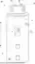
FIG. 1 provides a perspective view of a water heater appliance according to an example embodiment of the present disclosure.
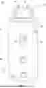
FIG. 2 provides a schematic view of certain components of the example water heater appliance of FIG. 1.
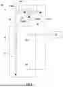
FIG. 3 provides a diagrammatic view of the example water heater appliance of FIG. 1.
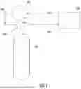
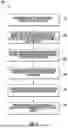
FIG. 4 provides a flowchart of an example method of operating a water heater appliance according to example embodiments of the present disclosure.
DETAILED DESCRIPTION OF THE INVENTION
Reference now will be made in detail to embodiments of the invention, one or more examples of which are illustrated in the drawings. The word “exemplary” is used herein to mean “serving as an example, instance, or illustration.” In addition, references to “an embodiment” or “one embodiment” does not necessarily refer to the same embodiment, although it may. Any implementation described herein as “exemplary” or “an embodiment” is not necessarily to be construed as preferred or advantageous over other implementations. Moreover, each example is provided by way of explanation of the invention, not limitation of the invention. In fact, it will be apparent to those skilled in the art that various modifications and variations may be made in the present invention without departing from the scope of the invention. For instance, features illustrated or described as part of one embodiment may be used with another embodiment to yield a still further embodiment. Thus, it is intended that the present invention covers such modifications and variations as come within the scope of the appended claims and their equivalents.
As used herein, the terms “first,” “second,” and “third” may be used interchangeably to distinguish one component from another and are not intended to signify location or importance of the individual components. The terms “includes” and “including” are intended to be inclusive in a manner similar to the term “comprising.” Similarly, the term “or” is generally intended to be inclusive (i.e., “A or B” is intended to mean “A or B or both”). The term “at least one of” in the context of, e.g., “at least one of A, B, and C” refers to only A, only B, only C, or any combination of A, B, and C. In addition, here and throughout the specification and claims, range limitations may be combined and/or interchanged. Such ranges are identified and include all the sub-ranges contained therein unless context or language indicates otherwise. For example, all ranges disclosed herein are inclusive of the endpoints, and the endpoints are independently combinable with each other. The singular forms “a,” “an,” and “the” include plural references unless the context clearly dictates otherwise.
Approximating language, as used herein throughout the specification and claims, may be applied to modify any quantitative representation that could permissibly vary without resulting in a change in the basic function to which it is related. Accordingly, a value modified by a term or terms, such as “generally,” “about,” “approximately,” and “substantially,” are not to be limited to the precise value specified. In at least some instances, the approximating language may correspond to the precision of an instrument for measuring the value, or the precision of the methods or machines for constructing or manufacturing the components and/or systems. For example, the approximating language may refer to being within a ten percent margin, i.e., including values within ten percent greater or less than the stated value. In this regard, for example, when used in the context of an angle or direction, such terms include within ten degrees greater or less than the stated angle or direction, e.g., “generally vertical” includes forming an angle of up to ten degrees in any direction, e.g., clockwise or counterclockwise, with the vertical direction V.
FIG. 1 provides a perspective view of a water heater appliance 100 according to an exemplary embodiment of the present subject matter. The water heater appliance 100 includes a casing 102. A tank 101 (FIG. 2) and heating elements 103 (FIG. 2) are positioned within casing 102 for heating water therein. The heating elements 103 may include a gas burner, a heat pump, an electric resistance element, a microwave element, an induction element, or any other suitable heating element or combination thereof. As will be understood by those skilled in the art and as used herein, the term “water” includes purified water and solutions or mixtures containing water and, e.g., elements (such as calcium, chlorine, and fluorine), salts, bacteria, nitrates, organics, and other chemical compounds or substances.
The water heater appliance 100 also includes a tank inlet conduit 104 and a tank outlet conduit 106 that are both in fluid communication with a chamber 111 (FIG. 2) defined by tank 101 within tank 101. As an example, fresh cold water from a water source, e.g., a municipal water supply or a well, may enter water heater appliance 100 through tank inlet conduit 104 (shown schematically with arrow labeled Finlet in FIG. 2). From tank inlet conduit 104, such cold water may enter chamber 111 of tank 101. However, as will be described below, relatively warm or relatively hot water that is a mixture of recirculated heated water and cold water from the water source may also enter chamber 111. Thereafter, the water that enters chamber 111 is heated within chamber 111 with heating elements 103 to generate heated water. Such heated water may exit chamber 111 at tank outlet conduit 106 and be supplied to a user end point, e.g., such as a bath, shower, sink, or any other suitable feature.
The water heater appliance 100 extends longitudinally between a top portion 108 and a bottom portion 110 along a vertical direction V. Thus, water heater appliance 100 is generally vertically oriented. The water heater appliance 100 may be leveled, e.g., such that casing 102 is plumb in the vertical direction V, in order to facilitate proper operation of water heater appliance 100. It should be understood that water heater appliance 100 is provided by way of example only and that the present subject matter may be used with any suitable water heater appliance.
FIGS. 2 and 3 provide differing views of water heater appliance 100 according to one or more exemplary embodiments. Specifically, FIG. 2 provides a schematic view of certain components of water heater appliance 100. FIG. 3 provides a diagrammatic view of water heater appliance 100. As may be seen in FIG. 2, in the illustrated exemplary embodiment, water heater appliance 100 includes a mixing valve 120 and a mixed water conduit 122. The mixing valve 120 is in fluid communication with tank inlet conduit 104, tank outlet conduit 106, and mixed water conduit 122. As discussed in greater detail below, mixing valve 120 is configured for selectively directing water from tank inlet conduit 104 and tank outlet conduit 106 into mixed water conduit 122 in order to regulate a temperature of water within mixed water conduit 122.
Referring again to the particular example embodiment illustrated in FIG. 2, the mixing valve 120 may selectively adjust between a first position and a second position. In the first position, mixing valve 120 may permit a first flow rate of relatively cool water from tank inlet conduit 104 (shown schematically with arrow labeled Finlet in FIG. 2) into mixed water conduit 122 and mixing valve 120 may also permit a first flow rate of relatively hot water from tank outlet conduit 106 (shown schematically with arrow labeled Foutlet in FIG. 2) into mixed water conduit 122. In such a manner, water within mixed water conduit 122 (shown schematically with arrow labeled Foutlet in FIG. 2) may have a first particular temperature when mixing valve 120 is in the first position. Similarly, mixing valve 120 may permit a second flow rate of relatively cool water from tank inlet conduit 104 into mixed water conduit 122 and mixing valve 120 may also permit a second flow rate of relatively hot water from tank outlet conduit 106 into mixed water conduit 122 in the second position. The first and second flow rates of the relatively cool water and relatively hot water are different such that water within mixed water conduit 122 may have a second particular temperature that is different from the first particular temperature when mixing valve 120 is in the second position. In such a manner, mixing valve 120 may regulate the temperature of water within mixed water conduit 122 and adjust the temperature of water within mixed water conduit 122 between the first and second particular temperatures.
It should be understood that, in certain exemplary embodiments, mixing valve 120 is adjustable between more positions than the first and second positions. In particular, mixing valve 120 may be adjustable between any suitable number of positions in alternative exemplary embodiments. For example, mixing valve 120 may be infinitely adjustable between and including a full cold position and a full hot position, in order to permit fine-tuning of the temperature of water within mixed water conduit 122.
It should be understood that in alternative exemplary embodiments, water heater appliance 100 need not include mixed water conduit 122. In such exemplary embodiments, mixing valve 120 may direct water into tank outlet conduit 106 in order to regulate a temperature of water within tank outlet conduit 106. Additionally, embodiments of the present invention may also include a water heater appliance without a mixing valve or a mixed water conduit, e.g., where the tank inlet conduit 104 and the tank outlet conduit 106 are each connected to the other only through the tank 101, as noted above.
In additional exemplary embodiments, water heater appliance 100 may be connected to a plumbing system, such as a residential plumbing system in a domicile as is generally understood by those of ordinary skill in the art. An exemplary plumbing system, or portion thereof, is schematically illustrated in FIG. 3. As may be seen, e.g., in FIG. 3, heated water may flow from the water heater appliance 100 to an end point 142 via the mixed water conduit 122 (and other downstream conduits which may be connected between the water heater appliance 100 and the end point 142). As illustrated in FIG. 3, the plumbing system may include a recirculation conduit 140 (FIG. 3) that is in fluid communication with a user end point 142, such as a bath, shower, sink, or any other suitable feature, and tank inlet conduit 104. Specifically, recirculation conduit 140 may be fluidly coupled between user end point 142 and tank inlet conduit 104 such that water flows from the end point 142 back to the water heater appliance 100 via the recirculation conduit 140. As such, recirculated water, which may include water from mixed water conduit 122 that was unused at user end point 142, may flow through recirculation conduit 140 and enter tank inlet conduit 104. In this respect, the recirculated water may be mixed with the cold water from the water source in tank inlet conduit 104 prior to entering tank 101.
Furthermore, the plumbing system may include a recirculation pump 150 (FIG. 3) that is in fluid communication with recirculation conduit 140. The recirculation pump 150 may be operated to pump the recirculated water through the recirculation conduit 140 to the tank inlet conduit 104. As will be described below, the recirculation pump 150 may be in communication with or operatively coupled to a controller 134 of the water heater appliance 100. As such, controller 134 may selectively operate the recirculation pump 150 to pump the recirculated water through the recirculation conduit 140 and to halt pumping of the recirculated water through the recirculation conduit 140.
The water heater appliance 100 also includes a tank inlet conduit temperature sensor 130. The tank inlet conduit temperature sensor 130 is positioned on or proximate to tank inlet conduit 104 and is configured to generate data indicative of a water temperature within tank inlet conduit 104. The tank inlet conduit temperature sensor 130 is positioned upstream of mixing valve 120. In certain exemplary embodiments, tank inlet conduit temperature sensor 130 may be positioned proximate to or adjacent to mixing valve 120.
The water heater appliance 100 further includes a controller 134 (FIG. 2) that is configured for regulating operation of water heater appliance 100. The controller 134 is in, e.g., operative, communication with heating elements 103, mixing valve 120, water conduit temperature sensor 130, and recirculation pump 150. Thus, controller 134 may selectively activate heating elements 103 in order to heat water within chamber 111 of tank 101. Similarly, controller 134 may selectively operate mixing valve 120 in order to adjust a position of mixing valve 120 and regulate a temperature of water within mixed water conduit 122. Furthermore, controller 134 may selectively operate recirculation pump 150 to pump recirculated water through recirculation conduit 140 and/or to halt pumping of the recirculated water through recirculation conduit 140.
The controller 134 includes memory and one or more processing devices such as microprocessors, CPUs or the like, such as general or special purpose microprocessors operable to execute programming instructions or micro-control code associated with operation of water heater appliance 100. The memory may represent random access memory such as DRAM, or read only memory such as ROM or FLASH. The processor executes programming instructions stored in the memory. The memory may be a separate component from the processor or may be included onboard within the processor. Alternatively, controller 134 may be constructed without using a microprocessor, e.g., using a combination of discrete analog and/or digital logic circuitry (such as switches, amplifiers, integrators, comparators, flip-flops, AND gates, and the like) to perform control functionality instead of relying upon software.
The controller 134 may be programmed to operate the water heater appliance 100 by executing instructions stored in memory. For example, the instructions may be software or any set of instructions that when executed by the processing device, cause the processing device to perform operations. The controller 134 may include one or more processor(s) and associated memory device(s) configured to perform a variety of computer-implemented functions and/or instructions (e.g. performing the methods, steps, calculations and the like and storing relevant data as disclosed herein). It should be noted that controllers 134 as disclosed herein are capable of and may be operable to perform any methods and associated method steps as disclosed herein.
The controller 134 may be positioned at a variety of locations. In the exemplary embodiment shown in FIG. 1, controller 134 is positioned within water heater appliance 100, e.g., as an integral component of water heater appliance 100. In alternative exemplary embodiments, controller 134 may be positioned away from water heater appliance 100 and communicate with water heater appliance 100 over a wireless connection or any other suitable connection, such as a wired connection.
The controller 134 may also include or be coupled to a user interface 136 (FIG. 1). The user interface 136 may comprise any suitable control or display that will allow a user to program, set, and adjust the functions and settings of the water heater appliance 100, as are generally described herein. In some exemplary embodiments, the user interface 136 may comprise a display interface, such as a touch screen display. In some exemplary embodiments, the user interface 136 may also or instead include mechanical buttons or switches for manipulating and programming the settings of the water heater appliance 100, including, for example, the setpoint temperature. In some exemplary embodiments, the user interface 136 may comprise or be part of a control panel for the water heater appliance 100. The user interface 136 may also be located remotely from the water heater appliance 100 and may be accessible through a computing device that is remote from the water heater appliance 100 or through a web-based interface.
The controller 134 may operate heating elements 103 to heat water within chamber 111 of tank 101. As an example, a user may select or establish a setpoint temperature for water within chamber 111 of tank 101, e.g., via the user interface 136 as described above, or the setpoint temperature for water within chamber 111 of tank 101 may be a default value. Based upon the setpoint temperature for water within chamber 111 of tank 101, controller 134 may selectively activate heating elements 103 in order to heat water within chamber 111 of tank 101 to the setpoint temperature for water within chamber 111 of tank 101. The setpoint temperature for water within chamber 111 of tank 101 may be any suitable temperature. For example, the setpoint temperature for water within chamber 111 of tank 101 may be between about one hundred and forty degrees Fahrenheit and about one hundred and eighty degrees Fahrenheit.
The controller 134 may also operate mixing valve 120 to regulate the temperature of water within mixed water conduit 122. For example, controller 134 may adjust the position of mixing valve 120 in order to regulate the temperature of water within mixed water conduit 122. As an example, a user may select or establish a setpoint temperature of mixing valve 120, or the setpoint temperature of mixing valve 120 may be a default value. Based upon the setpoint temperature of mixing valve 120, controller 134 may adjust the position of mixing valve 120 in order to change or tweak a ratio of relatively cool water flowing into mixed water conduit 122 from tank inlet conduit 104 and relatively hot water flowing into mixed water conduit 122 from tank outlet conduit 106. In such a manner, controller 134 may regulate the temperature of water within mixed water conduit 122.
The setpoint temperature of mixing valve 120 may be any suitable temperature. For example, the setpoint temperature of mixing valve 120 may be between about one hundred degrees Fahrenheit and about one hundred and twenty degrees Fahrenheit. In particular, the setpoint temperature of mixing valve 120 may be selected such that the setpoint temperature of mixing valve 120 is less than the setpoint temperature for water within chamber 111 of tank 101. In such a manner, mixing valve 120 may utilize water from tank inlet conduit 104 and tank outlet conduit 106 to regulate the temperature of water within mixed water conduit 122.
The controller 134 may also operate recirculation pump 150 in order to regulate the temperature of water supplied to tank 101 by tank inlet conduit 104. For example, controller 134 may activate or initiate operation of recirculation pump 150 to pump recirculated water through recirculation conduit 140 and/or deactivate or halt operation of recirculation pump 150 to halt pumping of recirculated water through recirculation conduit 140. The recirculated water may include heated water unused by the user at the user endpoint. As such, once the recirculated water has been pumped to tank inlet conduit 104, the recirculated water may mix with the cold water within the tank inlet conduit 104, such as the cold water from the water supply, to create mixed water that is warmer/hotter than the cold water from the water supply. The supply of such mixed water to the tank 101 and/or to the mixing valve 120 permits the water heater appliance 100 to run more efficiently. For example, warmer/hotter water may be supplied to the user endpoint using less heated water that was heated within chamber 111 by the heating elements 103. Furthermore, controller 134 may initiate or halt operation of recirculation pump 150 based on the data indicative of the water temperature within tank inlet conduit 104 generated by tank inlet water temperature sensor 130.
Turning now to FIG. 4, an embodiment of the present disclosure may include a method for operating a water heater appliance, such as the exemplary water heater appliance 100 described above.
As shown in FIG. 4, method 400 may include determining or detecting that a supply of heated water is required at a user end point, e.g., as indicated at step 410 in FIG. 4. For example, for the water heater appliance 100 described above, the controller 134 may determine or detect that a supply of heated water is required at a user end point, such as when a hot water faucet lever to a sink, shower, or bathtub is turned on. In some embodiments, when determining or detecting that a supply of heated water is required at a user end point, the controller 134 may be configured to receive a selected temperature of the supply of heated water that is required at the user end point. For example, the controller 134 may receive the temperature selected by the user, such as when the user adjusts the faucet levers/knobs.
Additionally, in some optional embodiments, the method 400 may include operating a mixing valve to adjust a ratio of water that passes through the mixing valve based on the supply of heated water that is required at the user end point, e.g., as indicated at step 420 in FIG. 4. For example, controller 134 may be configured to operate the mixing valve 120 such that the ratio of water heated within chamber 111 of tank 101 and the mixed water from tank inlet conduit 104 is adjusted according to the user selected temperature of the supply of heated water required at the user end point.
After detecting that the supply of heated water is required at the user end point, the method 400 may include a step 430 of receiving temperature sensor data indicative of a water temperature within a water conduit of (e.g., connected to, such as upstream of) a water heater appliance. For example, the controller 134 may receive the temperature sensor data. The data may be generated from the tank inlet temperature sensor 130, which may be mounted or coupled to the tank inlet conduit 104 of water heater appliance 100 to directly monitor the water temperature of the water flowing through tank inlet conduit 104. The temperature sensor 130 may be mounted downstream of a location in which the recirculated water enters the tank inlet conduit 104 so that the temperature sensor 130 may directly monitor the water temperature of the mixed water provided to the tank 101 and/or the water temperature of the mixed water bypassing the tank 101 by directly entering the mixing valve 120.
Thereafter, method 400 may include measuring the water temperature within the water conduit based on the received temperature sensor data, e.g., as indicated at step 440 in FIG. 4. For example, the controller 134 may measure/determine the water temperature within tank inlet conduit 104 from the received tank inlet temperature sensor data, e.g., by accessing a lookup table stored within a controller memory and correlating the received data with temperature values.
Additionally, method 400 may include comparing the measured water temperature within the water conduit to a temperature threshold, e.g., as indicated at step 450 in FIG. 4. For example, controller 134 may compare the temperature within the tank inlet conduit 104 measured at step 440 to the temperature threshold. In some embodiments, the temperature threshold is less than a user selected temperature, such as a set point temperature or a user end point temperature. It should be appreciated that the temperature threshold may correspond to a temperature threshold predetermined or pre-programmed into controller 134. Thus, for example, water in the tank 111 may be heated to a temperature greater than the user end point temperature, whereas the temperature of the water in the tank inlet conduit 104 is maintained less than the user end point temperature, whereby the two flows of water may be mixed, e.g., by and within mixing valve 120, to arrive at a mixed flow (Fmixed) at the desired user end point temperature.
Thereafter, the method 400 may include operating a recirculation pump based on the measured water temperature within the water conduit, e.g., as indicated at step 460 in FIG. 4. For example, in some embodiments, controller 134 may operate/activate the recirculation pump 150 to initiate or begin pumping of the recirculated water to the tank inlet conduit 104 in response to the water temperature measured at step 440 falling below the temperature threshold described above with respect to step 450. In this respect, controller 134 may make the water heater appliance 100 more efficient by supplying warm/hot water to the water inlet conduit 104 to be supplied to the tank 101 and/or the mixing valve 120. Alternatively, controller 134 may deactivate the recirculation pump 150 to halt pumping of the recirculated water to the tank inlet conduit 104 in response to the water temperature measured at step 440 equaling or exceeding the temperature threshold described above with respect to step 450, whereby the temperature of water supplied to the mixing valve 120 via the tank inlet conduit 104 remains below the user end point temperature, e.g., for mixing as described above.
This written description uses examples to disclose the invention, including the best mode, and also to enable any person skilled in the art to practice the invention, including making and using any devices or systems and performing any incorporated methods. The patentable scope of the invention is defined by the claims, and may include other examples that occur to those skilled in the art. Such other examples are intended to be within the scope of the claims if they include structural elements that do not differ from the literal language of the claims, or if they include equivalent structural elements with insubstantial differences from the literal languages of the claims.
Claims
What is claimed is:1. A method of operating a water heater appliance, the water heater appliance comprising a tank and a mixing valve, the method comprising:
determining, with a controller, that a supply of heated water is required at a user end point;
receiving, with the controller, temperature sensor data indicative of a water temperature within a tank inlet conduit of the water heater appliance, the tank inlet conduit providing a flow of water into at least one of the tank for heating or directly to the mixing valve for mixing with heated water from the tank, the flow of water provided comprising a mixture of recirculated water and water from a water source;
measuring, with the controller, the water temperature within the tank inlet conduit based on the received temperature sensor data; and
operating, with the controller, a recirculation pump based on the measured water temperature within the tank inlet conduit, the recirculation pump configured to pump the recirculated water to the tank inlet conduit.
2. The method of claim 1, wherein operating the recirculation pump comprises:
comparing, with the controller, the measured water temperature within the tank inlet conduit to a temperature threshold; and
operating, with the controller, the recirculation pump to initiate pumping of the recirculated water to the tank inlet conduit in response to the measured water temperature falling below the temperature threshold.
3. The method of claim 1, wherein operating the recirculation pump comprises:
comparing, with the controller, the measured water temperature within the tank inlet conduit to a temperature threshold; and
operating, with the controller, the recirculation pump to halt pumping of the recirculated water to the tank inlet conduit in response to the measured water temperature equaling or exceeding the temperature threshold.
4. The method of claim 3, wherein the temperature threshold is less than a user selected temperature of the supply of heated water that is required at the user end point.
5. The method of claim 3, wherein the temperature threshold comprises a predetermined temperature threshold.
6. The method of claim 1, wherein:
determining that the supply of heated water is required at a user end point comprises receiving, with the controller, a selected temperature of the supply of heated water that is required at the user end point;
the method further comprises operating, with the controller, the mixing valve to adjust a ratio of water that passes through the mixing valve based on the selected temperature of the supply of the heated water that is required at the user end point;
water that passes through the mixing valve is supplied to the user end point; and
the ratio of water that passes through the mixing valve comprises a ratio of water heated within the tank and water provided by the tank inlet conduit directly to the mixing valve.
7. A method of operating a water heater appliance, the water heater appliance comprising a tank and a mixing valve, the method comprising:
receiving, with a controller, temperature sensor data indicative of a water temperature within a water conduit fluidly coupled to the tank of the water heater appliance;
measuring, with the controller, the water temperature within the water conduit based on the received temperature sensor data; and
operating, with the controller, a recirculation pump based on the measured water temperature within the water conduit, the recirculation pump configured to pump recirculated water to a tank inlet conduit, the tank inlet conduit providing a flow of water into at least one of the tank for heating or the mixing valve for mixing with heated water from the tank, the flow of water provided comprising a mixture of the recirculated water and water from a water source.
8. The method of claim 7, wherein operating the recirculation pump comprises:
comparing, with the controller, the measured water temperature within the water conduit to a temperature threshold; and
operating, with the controller, the recirculation pump to initiate pumping of the recirculated water to the tank inlet conduit in response to the measured water temperature falling below the temperature threshold.
9. The method of claim 7, wherein operating the recirculation pump comprises:
comparing, with the controller, the measured water temperature within the water conduit to a temperature threshold; and
operating, with the controller, the recirculation pump to halt pumping of the recirculated water to the tank inlet conduit in response to the measured water temperature equaling or exceeding the temperature threshold.
10. The method of claim 9, wherein the temperature threshold is less than a user selected temperature of a supply of heated water that is required at a user end point.
11. A water heater appliance for coupling to a plumbing system, the plumbing system comprising a user end point at which water is supplied to a user, a recirculation conduit fluidly coupled between the user end point and the water heater appliance for providing a flow of recirculated water to the water heater appliance, and a recirculation pump configured to pump the recirculated water through the recirculation conduit, the water heater appliance comprising:
a tank for holding a volume of water therein for heating;
a tank outlet conduit fluidly coupled to the tank and a mixing valve of the water heater appliance for providing a flow of heated water from the tank to the mixing valve, the mixing valve operable to adjust a ratio of the flow of recirculated water and the flow of heated water provided to the user end point;
a temperature sensor configured to generate data indicative of a water temperature within the water heater appliance;
a controller operatively coupled to the recirculation pump and the temperature sensor, the controller configured to:
operate the recirculation pump based on the data generated by the temperature sensor.
12. The water heater appliance of claim 11, wherein the controller is configured to operate the recirculation pump to halt pumping of the recirculated water in response to the data generated by the temperature sensor indicating that the water temperature within the water heater appliance has reached or exceeded a temperature threshold.
13. The water heater appliance of claim 11, wherein the controller is configured to operate the recirculation pump to initiate pumping of the recirculated water in response to the data generated by the temperature sensor indicating that the water temperature within the water heater appliance has fallen below a temperature threshold.
14. The water heater appliance of claim 13, wherein the temperature threshold is less than a user selected temperature of the water supplied to the user at the user end point.
15. The water heater appliance of claim 11, further comprising:
the mixing valve; and
a tank inlet conduit, the tank inlet conduit coupled to the tank and to the mixing valve for providing a flow of water to at least one of the tank or directly to the mixing valve, the tank inlet conduit coupled to a water source for receiving a flow of fresh water from the water source,
wherein:
the recirculation conduit is fluidly coupled to the tank inlet conduit for providing the recirculated water to the tank inlet conduit; and
the flow of water provided by the tank inlet conduit to the at least one of the tank or the mixing valve comprises a mixture of the recirculated water and the fresh water from the water source.
16. The water heater appliance of claim 15, wherein:
the temperature sensor is positioned on the tank inlet conduit thereby permitting the temperature sensor to generate data indicative of a water temperature of the mixture of the recirculated water and the fresh water from the water source.
Images & Drawings included:
Sources:
- United States Patent and Trademark Office - verify current appl. status at the USPTO↗
Similar patent applications:
- » 20150184889
Water heater appliance and a method for operating a water heater appliance - » 20200049377
Water heater appliance and a method for operating a water heater appliance - » 20160069574
HEAT PUMP WATER HEATER APPLIANCE AND A METHOD FOR OPERATING A HEAT PUMP WATER HEATER APPLIANCE - » 20140217188
Method for operating a water heater appliance - » 20190285312
Water heater appliance and methods of operation - » 20150241093
Water heater appliances and methods for operating same - » 20150354855
Method for operating a water heater appliance - » 20140217187
Method for operating a water heater appliance - » 20160313029
Method for operating a water heater appliance - » 20150013622
Water heater appliance and a method for operating the same
Recent applications in this class:
- » 20260153269 2026-06-04
CONTROLLER AND PROCESS TO OPERATE A WATER HEATER - » 20250354721 2025-11-20
WATER-DISPENSING SYSTEM FOR GENERATING BOILED WATER OF DIFFERENT TEMPERATURES - » 20250314395 2025-10-09
HOT WATER APPARATUS - » 20250180250 2025-06-05
WATER HEATER - » 20240240830 2024-07-18
SYSTEM AND METHOD FOR USING WASTE HEAT GENERATED BY DIGITAL PROCESSING COMPONENTS - » 20240183582 2024-06-06
HEAT PUMP WATER HEATER - » 20240175607 2024-05-30
WATER BOILER WITH DUAL HEATING FUNCTIONALITY - » 20240167727 2024-05-23
Tankless Hot Water Heater - » 20240159430 2024-05-16
Apparatus for determining duration of hot water release from a boiler - » 20240093908 2024-03-21
Methods and systems for modulating energy usage