Fan
US20260177293A1
2026-06-25
19/094,548
2025-03-28
Smart Summary: A fan has a special circuit board that connects different parts to control the airflow. It includes a fan module that pulls air in and a temperature control module that manages how hot or cold the air is. This temperature control module has two main parts: a cooling plate for cold air and a hot plate for hot air. The design separates the cold and hot areas, allowing the fan to create both cold and hot air. Cold air comes out of one outlet, while hot air comes out of another outlet. 🚀 TL;DR
Abstract:
A fan includes a circuit board, a fan module, and a temperature control module. The fan module is electrically connected to the circuit board and located at an air inlet. The temperature control module is electrically connected to the circuit board and communicated with the fan module. The temperature control module includes at least one semiconductor chilling plate, a cooling plate component and a hot plate component. The semiconductor chilling plate separates a cold zone provided with the cooling plate component from a hot zone provided with the hot plate component. The cold zone and the hot zone are arranged oppositely. The fan module divides airflow passing through the cooling plate component and the hot plate component to turn into cold air and hot air. The cold air goes out from a cold air outlet, and hot air goes out from an hot air outlet.
Applicant:
Interested in similar patents?
Get notified when new applications in this technology area are published.
Classification:
F25B21/04 » CPC main
Machines, plants or systems, using electric or magnetic effects using Peltier effect; using Nernst-Ettinghausen effect reversible
F04D19/002 » CPC further
Axial-flow pumps Axial flow fans
F04D29/541 » CPC further
Details, component parts, or accessories; Casings; Connections of working fluid for axial pumps; Fluid-guiding means, e.g. diffusers Specially adapted for elastic fluid pumps
F04D19/00 IPC
Axial-flow pumps
F04D29/54 IPC
Details, component parts, or accessories; Casings; Connections of working fluid for axial pumps Fluid-guiding means, e.g. diffusers
Description
CROSS-REFERENCE TO RELATED APPLICATIONS
The present application claims the benefit of Chinese Patent Application No. 2024119452428 filed on Dec. 24, 2024, the contents of which are hereby incorporated by reference.
TECHNICAL FIELD
The present application relates to the technical field of fans, and particularly to a fan.
TECHNICAL BACKGROUND
With the development of technology, people pursuit a high quality of life. In the hot summer, people have demands for cooling equipment. Traditional fans can only bring a certain sense of coolness through air flow, but fails to provide users with cold air.
INVENTION CONTENT
The present application provides a fan that can effectively separate cold air and hot air to improve cooling efficiency.
The present application provides a fan, including a circuit board, a fan module and a temperature control module, wherein the fan module is electrically connected to the circuit board and located at an air inlet; the temperature control module is electrically connected to the circuit board and communicated with the fan module. The temperature control module further includes at least one semiconductor chilling plate, a cooling plate component and a hot plate component. The semiconductor chilling plate divides a cold zone and a hot zone which are arranged relatively. The cooling plate component is arranged in the cold zone, and the hot plate component is arranged in the hot zone. The fan module is used to guide airflow entering into the temperature control module. The airflow passes through the cooling plate component located in the cold zone and the hot plate component located in the hot zone separately becoming cold air and hot air; the cold air and hot air respectively flow out through the cold air outlet and the hot air outlet. The fan provided by the present application adopts semiconductor chilling plate technology so that the fan can directly convert the heat of the airflow between the cold zone and the hot zone, so as to generate cold air and hot air; the cooling plate component arranged in the cold zone effectively absorbs heats and cool the airflow to form cold air; and the hot plate component is arranged in the hot zone dissipates the heat in time to avoid heat accumulation affecting the cooling effect. This design enables the fan to maintain efficient operation during the cooling process and quickly cool down the temperature of the surrounding environment; Arranging the cold air outlet and hot air outlet separately ensures that the cold air and hot air are not mixed inside the fan, and then flow out independently, so as to realize effective separation of cold air and hot air to improve cooling efficiency, avoid energy loss and discomfort caused by the mixing of cold and hot air. Therefore, users can control the fan to blow out cold air or hot air according to their needs. Therefore, the fan can meet the usage requirements in different scenarios.
DESCRIPTION OF FIGURES
In order to more clearly illustrate the technical solutions in the embodiments of the present application, the drawings required for use in the description of the embodiments will be briefly introduced below. Obviously, the drawings described below are only some embodiments of the present application. For those skilled in the art, other drawings can be obtained based on these drawings without creative work.
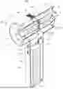
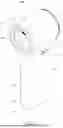
FIG. 1 is a schematic view of the three-dimensional structure of the horizontal air intake method of the fan provided in the embodiment of the present application.
FIG. 2 is a cross-sectional view at F-F of the horizontal air intake method of the fan provided in the embodiment of the present application.
FIG. 3 is a front view of the horizontal air intake method of the fan provided in the embodiment of the present application.
FIG. 4 is a rear view of the horizontal air intake method of the fan provided in the embodiment of the present application.
FIG. 5 is a top view of the horizontal air intake method of the fan provided in the embodiment of the present application.
FIG. 6 is a bottom view of the horizontal air intake method of the fan provided in the embodiment of the present application.
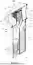
FIG. 7 is a schematic view of the three-dimensional structure of the bottom air intake method of the fan provided in the embodiment of the present application.
FIG. 8 is a cross-sectional view at H-H of the bottom air intake method of the fan provided in the embodiment of the present application.
FIG. 9 is a front view of the bottom air intake method of the fan provided in the embodiment of the present application.
FIG. 10 is a rear view of the bottom air intake method of the fan provided in the embodiment of the present application.
FIG. 11 is a top view of the bottom air intake method of the fan provided in the embodiment of the present application.
FIG. 12 is a bottom view of the bottom air intake method of the fan provided in the embodiment of the present application.
DESCRIPTION OF MARKS IN FIGURES
-
- 10—circuit board 100—fan 110—temperature detection module 120—control switch 130—air inflow distribution plate 140—refrigerating switch 150—power switch 160—power supply
- 20—fan module 21—fan motor 22—fan blade
- 30—temperature control module 301—cold zone 302—hot zone 31—semiconductor chilling plate 32—cooling plate component 33—hot plate component
- 40—air inlet 50—cold air outlet 60—hot air outlet
- 70—grip part 71—air passage
- 80—ventilation section
- 90—deflector device 91—first deflector 92—second deflector 93—third deflector
- A—airflow B—cold air C—hot air
DETAILED DESCRIPTION OF THE EMBODIMENTS
Below is a further detailed description of the present invention based on the figures.
The present embodiments only show explanations of the present invention and it is not a limitation to the present invention. The skilled in the art can make modifications to this embodiment as needed without making any creative contributions after reading this specification, which are always protected by the patent law as long as they are within the scope of the claims of the present invention.
In the description of the present application, it should be understood that the terms “center”, “longitudinal”, “lateral”, “length”, “width”, “thickness”, “above”, “below”, “front”, “back”, “left”, “right”, “vertical”, “horizontal”, “top”, “bottom”, “inside”, “outside”, “clockwise”, “counterclockwise” which indicates the orientations or positional relationships are based on the orientations or positional relationships shown in the figures. They are only for facilitating describing the present invention and simplifying the description, rather than indicating or implying that the device or component must have a specific orientation, construct and operate in a specific orientation. Therefore, it cannot be understood as a limitation of the present invention. In addition, the terms “first” and “second” are only used for descriptive purposes and cannot be understood as indicating or implying relative importance or implicitly indicating the number of technical features indicated. Therefore, the features defined as “first” and “second” may explicitly or implicitly include one or more of the features. In the description of the present application, the meaning of “multiple” is two or more, unless otherwise clearly and specifically defined.
In the description of the present application, it should be noted that, unless otherwise clearly specified and limited, the terms “install”, “connected with”, and “connect” should be understood in a broad sense. For example, it can be a fixed connection, a detachable connection, or an integral connection; it can be a mechanical connection, an electrical connection, or mutual communication; it can be a direct connection, or an indirect connection through an intermediate medium, it can be the internal connection of two elements or the interaction relationship between two elements. For ordinary technicians in this field, the specific meanings of the above terms in this application can be understood according to specific circumstances.
In the present application, unless otherwise clearly specified and limited, a first feature being “above” or “below” a second feature may include that the first and second features are in direct contact or may include that the first and second features are not in direct contact but are in contact through another feature between them. Moreover, a first feature being “above” “over” “on top of” a second feature includes that the first feature is directly above and obliquely above the second feature or simply indicates that the first feature is higher in level than the second feature. A first feature being “below” “under” “at bottom of” a second feature includes that the first feature is directly below and obliquely below the second feature or simply indicates that the first feature is lower in level than the second feature.
The disclosure below provides many different embodiments or examples to realize the different structures of the present application. In order to simplify the disclosure of the present application, the parts and settings of specific examples are described below. Of course, they are only examples, instead of limiting the present application. In addition, the present application can repeat reference numbers and/or reference letters in different examples, and this repetition is for the purpose of simplification and clarity, which does not indicate the relationship between the various embodiments and/or settings discussed. In addition, the various specific processes and material examples provided by the present application, but those of ordinary skill in the art can appreciate the application of other processes and/or the use of other materials.
Specifically, referring to FIGS. 1 to 12, the present application provides a fan 100, which includes a circuit board 10, a fan module 20, and a temperature control module 30.
The circuit board 10, as the core control component of the fan 100, receives and processes external operation instructions and/or signals from different components, and the circuit board 10 controls the working states of the fan module 20 and the temperature control module 30 according to these signals. The circuit board 10 integrates necessary circuits and components, such as a processor, a drive circuit, a power management and so on to ensure the stable operation of the entire fan 100.
The fan module 20 electrically connected to the circuit board 10 is located at the air inlet 40.
For example, the fan module 20 is mainly used to absorb external air into the fan. The fan module 20 is powered and controlled by the circuit board 10. Users can control the speed of fan module 20 to adjust the air volume. The fan module 20 also includes a fan motor 21 and fan blades 22. When the fan motor 21 is turned on, the fan blades 22 rotate, thereby absorb external air into the fan to form airflow A. The airflow A flows into the temperature control module 30 with the help of the fan module 20 to achieve air circulation and heat exchange.
The temperature control module 30 electrically connected to the circuit board 10 is communicated with the fan module 20. The temperature control module 30 includes at least one semiconductor chilling plate 31, a cooling plate component 32 and a hot plate component 33. The semiconductor chilling plate 31 divides a cold zone 301 and a hot zone 302 which are arranged oppositely on two sides of the semiconductor chilling plate 31. The cooling plate component 32 is arranged in the cold zone 301 and the hot plate component 33 is arranged in the hot zone 302.
For example, the semiconductor chilling plate 31 works based on the Peltier effect, which is a thermoelectric effect. When a source of direct current passes through an electric couple formed by two different semiconductor materials in series, one end of the electric couple will absorb heat while other end of the electric couple will release heat, thereby achieving the purpose of cooling. The semiconductor chilling plate 31 is composed of P-type and N-type semiconductor materials. When direct current passes through these materials, heat will be transferred from the input end of current to the output end. A cold zone 301 and a hot zone 302 are formed respectively. When the fan is on, the cold zone 301 absorbs heat and the hot zone 302 releases heat. The cooling plate component 32 arranged in the cold zone 301 is used to enhance the cooling effect. The hot plate component 33 arranged in the hot zone 302 is used to enhance the heat dissipation effect. The cold zone 301 is provided with the cooling plate component 32 and the hot zone 302 is provided with the hot plate component 33 to achieve the separation of cold airflow and hot airflow.
In the embodiment, a base plate of the semiconductor chilling plate 31 can be made of metal with high thermal conductivity, such as copper (Cu) or silver (Ag), to replace the traditional ceramic (aluminum oxide) base plate. The high thermal conductivity metal base plate improves the thermal utilization rate and enhances the cooling and heating effects.
The fan module 20 is used to guide the airflow A entering into the temperature control module 30. The airflow A passes through the cooling plate component 32 located in the cold zone 301 and the hot plate component 33 located in the hot zone 302 of the temperature control module 30 to form cold air B and hot air C respectively. The cold air B and hot air C respectively flow out through the cold air outlet 50 and the hot air outlet 60, so as to realize the temperature control and airflow regulation functions of the fan 100.
In some embodiments, as shown in FIG. 2 or FIG. 8, the fan 100 includes a grip part 70 and a ventilation section 80 that are perpendicular to each other. The grip section 70 is used for users to hold the fan, and the temperature control module 30 is located in the ventilation section 80.
The grip part 70 and the ventilation section 80 of the fan 100 are perpendicular to each other. This design makes the fan 100 easy for users to hold the fan by one hand or two hands, also ensures that the ventilation section 80 has enough space to accommodate the temperature control module 30 and other components.
The design of the grip part 70 takes the users' experience into full consideration, and its shape, size and material are carefully selected to ensure that users can comfortably and firmly hold the fan 100. At the same time, the grip part 70 can be equipped with material of anti-slip characteristic, anti-sweat characteristic and other characteristics to further improve users' comfort.
The ventilation section 80 is the core functional area of the fan 100. The ventilation section 80 includes key components such as the fan module 20 and the temperature control module 30. The temperature control module 30 is located in the ventilation section 80 and works closely with the fan module 20 to jointly achieve airflow regulation and temperature control.
In some embodiments, as shown in FIGS. 1 to 6, the fan 100 absorbs air in a horizontal direction. The fan module 20 and the temperature control module 30 are horizontally arranged in the ventilation section 80, the hot zone 302 and the cold zone 301 are vertically arranged on two sides of the semiconductor chilling plate 31, the air inlet 40 is located at one side of the ventilation section 80, the air flow A enters from the air inlet 40 into the cold zone 301 and the hot zone 302. The cold air B generated in the cold zone 301 flows out from the cold air outlet 50 arranged at the opposite side of the ventilation section 80, and the hot air C generated in the hot zone 302 flows out from the hot air outlet 60 on the upper part of the ventilation section 80.
Further, the fan module 20 and the temperature control module 30 are arranged horizontally in the ventilation section 80. This layout not only makes the structure of the fan 100 more compact but also helps to improve the circulation efficiency of the airflow and the accuracy of temperature control. The semiconductor chilling plate 31 is the core component of the temperature control module 30, and the hot zone 302 and cold zone 301 are vertically arranged in the ventilation section 80. This design utilizes the natural convection principle that hot air rises and cold air falls, which helps to further separate the cold air B and the hot air C, and improves the working efficiency of the fan 100.
The air inlet 40 is located at one side of the ventilation section 80. This position selection helps users to hold the fan 100 without blocking the airflow. After the airflow A enters through the air inlet 40, the fan module 20 guides the airflow A to enter into the cold zone 301 and the hot zone 302 to achieve heat exchange. This layout allows the cold air B and the hot air C to flow out effectively through different paths, thereby avoiding interference and mixture of the cold air and hot air.
The cold air B generated in the cold zone 301 flows out through the cold air outlet 50 at the opposite side of the air inlet 40. This design helps users to directly feel the blowing of the cold air B when holding the fan 100, providing users with a cool experience. The hot air C flows out through the hot air outlet 60 on the upper part of the ventilation section 80, which not only avoids the accumulation of hot air C inside the fan 100 which may influence the use effect, but also avoids the hot air C from blowing directly to users, so as to improve the use experience. This design not only ensures the separation and effective discharge of cold air flows and hot air flows, but also improves the heat dissipation efficiency of the fan and the user comfort.
In some embodiments, as shown in FIGS. 7 to 12, the fan 100 absorb air from a bottom side of the grip part 70. The air inlet 40 is located at the bottom of the grip part 70, and the fan module 20 is located inside the grip part 70. The cold zone 301 is arranged corresponding to the cold air outlet 50 at one side of the ventilation section 80, and the hot zone 302 is arranged corresponding to the hot air outlet 60 at the opposite side of the ventilation section 80. The fan module 20 guides the airflow A from the bottom of the grip part 70 to enter into the temperature control module 30 to form cold air B and hot air C respectively, and the cold air B flows out through the cold air outlet 50 and hot air C flows out through the hot air outlet 60.
Further, the air inlet 40 is arranged at the bottom of the grip part 70. This layout enables the fan 100 to naturally absorb air from the bottom of the grip part 70, so as to increase convenience and comfort of use.
Further, the fan module 20 is arranged inside the grip part 70, which not only saves space, but also effectively protects drive components of the fan 100. The fan module 20 generates and accelerates the airflow A, then absorb the airflow A from the air inlet 40 into the fan 100, and the airflow A flows out after passing though the cooling plate component 32 and the hot plate component 33.
The cold zone 301 and the hot zone 302 are arranged on two sides of the ventilation section 80. This layout helps to effectively separate the cold air B and the hot air C. The cold zone 301 is close to the cold air outlet 50 at one side, and the hot zone 302 is close to the hot air outlet 60 at other side. The cold air and hot air flow out from different outlets without interference.
The fan module 20 guides the airflow A to enter from the air inlet 40 at the bottom of the grip part 70 into the temperature control module 30, and the airflow passes through the semiconductor chilling plate 31 to become cold air B and hot air C. This design ensures that the airflow can be evenly distributed after entering the temperature control module 30, so as to improve the cooling and heating efficiency.
The cold air B flows out through the cold air outlet 50, and the hot air C flows out through the hot air outlet 60. This design allows users to feel the cold air B from one side and the hot air C flows out from the other side when holding the fan 100. This layout avoids the mixing of cold airflow and hot airflow, improves the heat dissipation efficiency of the fan, and avoids the hot air from blowing directly to users, so as to improve users' experience.
In some embodiments, as shown in FIG. 8, the fan 100 also includes a deflector device 90 located between the fan module 20 and the temperature control module 30. The deflector device 90 is used to guide the airflow A to enter into the cold zone 301 to form cold air B, or to guide the airflow A to enter into the hot zone 302 to form hot air C.
The deflector device 90 is arranged between the fan module 20 and the temperature control module 30 to guide a flow direction of the airflow A inside the temperature control module 30 to ensure that the airflow can efficiently pass through the cooling plate component 32 and the hot plate component 33 to form cold air B and hot air C.
In some embodiments, as shown in FIG. 8, the deflector device 90 includes a first deflector 91, a second deflector 92, and a third deflector 93;
-
- the first deflector 91 is arranged adjacent to the cold air outlet 50, and the cold zone is an air cavity formed by the first deflector 91 and the cooling plate component 32;
- the second deflector 92 is arranged adjacent to the hot air outlet 60, and the hot zone is another air cavity formed by the second deflector 92 and the hot plate component 33;
- the third deflector 93 is arranged at the lower end of the temperature control module 30. One end of the third deflector 93 is connected to the second deflector 92, and other end of the third deflector 93 extends to the air passage 71 of the grip part 70.
The first deflector 91 is arranged adjacent to the cold air outlet 50, and the cold zone 301 is an air cavity formed by the first deflector 91 and the cooling plate component 32. The design of the first deflector 91 helps guide the airflow A to enter into the cooling plate component 32 to promote the exchange of heat, and thus generates cold air B.
The second deflector 92 is arranged adjacent to the hot air outlet 60, and the hot zone 302 is another air cavity formed by the second deflector 92 and the hot plate component 33. The design of the second deflector 92 helps guide the airflow A to enter into the hot plate component 33 to promote the release of heat, and thus generates hot air C.
The third deflector 93 is arranged at the lower end of the temperature control module 30 to guide the airflow A in the air passage 71 to flow into the cold zone 301 and the hot zone 302 more effectively. By accurately designing the shape and angle of the third deflector 93, the distribution of the airflow can be optimized and the heat exchange efficiency can be improved. One end of the third deflector 93 is connected to the second deflector 92, and other end extends to the air passage 71. This design helps to further separate the cold air B and the hot air C. By controlling the path of the airflow, the mixture of the cold airflow and hot airflow can be reduced, so as to improve the purity of the cold air and the hot air.
In some embodiments, as shown in FIG. 8, the third deflector 93 is movably arranged at the lower end of the temperature control module. When the temperature control module 30 is turned on, the third deflector 93 guides the airflow A entering into the hot zone 302 to form hot air C. The second deflector guides the hot air flowing out through the hot air outlet, the first deflector guides cold air formed in the cold zone flowing out through the cold air outlet; or
-
- when the temperature control module 30 is turned off, the third deflector 93 blocks the airflow A from entering into the hot zone 302, and the airflow A enters into the cold zone 301 only under the guidance of the first deflector 91 and then flows out through the cold air outlet 50.
The movable arrangement of the third deflector 93 gives the deflector 90 higher flexibility and energy efficiency management capabilities. This design not only allows users to adjust the airflow path according to actual needs but also optimizes the heat exchange efficiency in different working modes, further improving the intelligence of the device and users experience.
For example, when the temperature control module 30 is activated, the third deflector 93 will automatically open to a predetermined position. This action ensures that the airflow A passing through the air passage 71 can enter into the hot zone 302 unimpeded. In the hot zone 302, the airflow A and the hot plate component 33 perform efficient heat exchange, thereby being heated to form hot air C. Subsequently, the second deflector 92 guides the hot air C to safely and orderly flow out through the hot air outlet 60 to the external environment, effectively avoiding the accumulation of heat inside the fan 100. At the same time, the third deflector 93 continues to guide another part of the airflow A into the cold zone 301, in which the airflow A and the cooling plate component 32 perform heat exchange and are cooled to form cold air B. Under the guidance of the first deflector 91, the cold air B flows out through the cold air outlet 50, providing a cooling effect for the fan 100 or the surrounding environment. This design ensures that the fan 100 can provide both cooling and heating functions during operation to meet the needs of a variety of application scenarios.
For example, when the temperature control module 30 is turned off, the third deflector 93 will be closed accordingly or adjusted to a position that blocks the airflow A from entering into the hot zone 302. This action effectively prevents unnecessary heat exchange, reduces energy waste, and helps to extend the service life of the equipment. While closing the third deflector 93, the first deflector 91 remains open and continues to guide the airflow A to enter into the cold zone 301. This means that even if the temperature control module 30 is turned off as a whole, the device can still maintain a certain degree of cooling capacity. The cold air B flowing out through the cold air outlet 50 can provide a continuous cooling effect for application scenarios that require a low temperature environment.
For example, the first deflector 91 and the second deflector 92 are movably arranged adjacent to the hot air outlet. When the fan 100 is turned on, the first deflector 91 guides the cold air B formed in the cold zone 301 to flow out through the cold air outlet 50, and the second deflector 92 guides the hot air C formed in the hot zone 302 to flow out through the hot air outlet 60. Therefore, it can provide users with the desired cooling effect. When the fan 100 is turned off, the first deflector 91 and the second deflector 92 are turned off to prevent foreign matter from entering into the fan 100, which effectively blocks the passage for foreign matter to enter into the fan 100, so as to protect the internal structure and components of the fan 100, and extend the service life of the fan 100.
For example, the operation of the deflector device 90 can be integrated with the intelligent control system of the fan 100, and the adjustment signal is received by the circuit board 10 to automatically adjust the states of the first deflector 91, the second deflector 92 and the third deflector 93 to achieve the output of the cold airflow and hot airflow required by users.
In some embodiments, as shown in FIG. 2 or FIG. 8, the fan 100 also includes a temperature detection module 110 electrically connected to the circuit board 10 to detect the temperature of the hot zone 302. When the temperature detection module 110 detects an abnormal temperature of the hot zone 302, the circuit board 10 controls the speed of the fan module 20 to cool the hot zone 302.
For example, the temperature detection module 110 may use a highly sensitive temperature sensor, such as a thermistor, a thermocouple or a digital temperature sensor and so on. These sensors can accurately capture the temperature changes of the hot zone 302, and convert these temperature changes into electrical signals and send them to the microprocessor or control unit on the circuit board 10. For example, the temperature detection module 110 can be arranged on the temperature control module 30, or be arranged adjacent to the temperature control module 30.
When the temperature detection module 110 detects that the temperature of the hot zone 302 exceeds the preset safety threshold or reaches an abnormally high temperature level, it will immediately send an alarm signal to the circuit board 10. Then the control logic on the circuit board 10 is activated, and the circuit board 10 can dynamically adjust the speed of the fan module 20 according to the received temperature data. This adjustment process is intended to accelerate air flow by increasing the speed of the fan, thereby taking away the heat of the hot zone 302 more effectively to achieve rapid cooling, and prevent possible equipment damage or performance degradation caused by overheating.
In addition, this intelligent temperature control mechanism can also include more complex algorithms for comprehensively judging and optimizing the speed adjustment strategy based on factors such as the rate of temperature change, the current ambient temperature, and the power consumption limit of the fan 100 and so on, so as to achieve the purpose of effective heat dissipation and energy saving.
By integrating the temperature detection module 110, the fan 100 can not only monitor and respond to the temperature changes of the hot zone 302 in real time, but also maintain the thermal stability of the fan 100 by intelligently adjusting the speed, to ensure that the fan 100 operates in the best condition, extends its service life, and improves overall energy efficiency.
In some embodiments, as shown in FIG. 2 or FIG. 8, the fan 100 also includes a control switch 120 electrically connected to the circuit board 10, and the control switch is used to generate a control instruction in response to a control operation. And the circuit board 10 controls the speed of the fan module 20 and/or the cooling capacity of the cold air B according to a control instruction.
For example, the control switch 120 may be arranged on the grip part 70. This design allows users to conveniently perform control operations when holding the fan 100 without having to search for or touch control elements in other locations.
For example, the control switch 120 may adopt a knob structure, and users adjust the speed of the fan module 20 and/or the cooling capacity of the temperature control module 30 by rotating the knob. The knob provides intuitive feedback, and users can perceive the current setting through the damping and scale of the knob.
When users operate the control switch 120, it generates corresponding control instructions. These control instructions are sent to the circuit board 10 through the circuit connection. After receiving the control instructions, the circuit board 10 adjusts the speed of the fan module 20 and/or the cooling capacity of the temperature control module 30.
For example, the circuit board 10 controls the speed of the fan module 20 by changing the supply voltage or supply current of the fan module 20 according to the control instruction of the control switch 120. At the same time, the circuit board 10 can also control the cooling capacity of the cold air B by adjusting the current of the semiconductor chilling plate 31.
For example, the fan 100 may also be equipped with an external temperature sensor for real-time monitoring of the ambient temperature or the temperature of the hot zone 302. The circuit board 10 may intelligently adjust the speed according to the detection data of the external temperature sensor to achieve variable frequency speed regulation, so as to maintain a suitable temperature difference.
In some embodiments, the fan 100 may also be equipped with a display screen or indicator light to provide feedback to users on the current speed and cooling capacity setting, to provide interactivity to users interface and enable users to clearly understand the working status of the fan.
By regulating the switch 120, users can adjust the working state of the fan 100 according to personal preference and actual needs to achieve a balance between energy saving and comfort.
For example, the control switch 120 can support the selection of multiple working modes, such as standard mode, energy-saving mode, strong mode and so on. Users can select the appropriate mode according to different usage scenarios.
By setting the control switch 120, the fan 100 not only provides a user-friendly control method, but also enhances the adaptability of the fan 100 and users' experience through intelligent speed regulation and multi-mode selection.
In some embodiments, as shown in FIG. 8, the fan 100 further includes an air inflow distribution plate 130 located between the cooling plate component 32 and the hot plate component 33. The air inflow distribution plate 130 is used to divert the airflow A remained in the fan module 20 to enter into the cooling plate component 32 and the hot plate component 33.
The air inflow distribution plate 130 is located between the cooling plate component 32 and the hot plate component 33. The air inflow distribution plate 130 evenly distributes the airflow A entering into the temperature control module 30 to the cooling plate component 32 and the hot hot plate component 33, so as to ensure that the cooling plate component 32 and the hot plate component 33 receive an appropriate amount of airflow for effective heat exchange. The design of the air inflow distribution plate 130 helps achieve even distribution of the airflow A between the cooling plate component 32 and the hot plate component 33. This even distribution is very important for improving the efficiency of cooling and heating because it ensures that both the cold zone 301 and the hot zone 302 of the semiconductor chilling plate 31 can achieve the best working state.
For example, the air inflow distribution plate 130 may be made of a light and strong material, such as plastic or metal alloy, to ensure that it can withstand the airflow pressure while maintaining a relatively light weight.
The shape and size of the air inflow distribution plate 130 need to be precisely designed according to the internal structure and airflow requirements of the fan 100. For example, the air inflow distribution plate 130 may have a streamlined shape to reduce airflow resistance. For example, the air inflow distribution plate 130 may also be equipped with appropriate guide chutes or holes to ensure that the airflow can be evenly distributed to the cooling plate component 32 and the hot plate component 33. For example, the air inflow distribution plate 130 may have a specific curved or bifurcated structure to guide the airflow to flow along a specific path.
The air inflow distribution plate 130 and the fan module 20 work together. The fan module 20 guides the airflow A to flow into the temperature control module 30, while the air inflow distribution plate 130 further distributes the airflow A to the cooling plate component 32 and the hot plate component 33.
For example, the design of the air inflow distribution plate 130 can also take into account the convenience of maintenance and cleaning. It can be easily disassembled so that users can easily clean or inspect it.
For example, the air inflow distribution plate 130 may be movably arranged between the cooling plate component and the hot plate component, allowing the air inflow distribution plate 130 to adjust its position or angle according to actual needs, so as to accurately control the airflow ratio flowing into the cooling plate component 32 and the hot plate component 33.
In order to achieve more intelligent airflow distribution, the air inflow distribution plate 130 can receive signals from the control switch 120 or other sensors through the circuit board 10. Specifically, users can select different working modes or set specific temperature values through the control switch 120. After receiving these instructions, the circuit board 10 will calculate the optimal airflow distribution ratio according to the preset algorithm and control the air inflow distribution plate 130 to move accordingly through the driving mechanism (such as a motor, an electromagnet, etc.).
In addition, if the fan 100 can also be equipped with other sensors (such as temperature sensors, humidity sensors, etc.), these sensors can monitor environmental parameters in real time and feed back the data to the circuit board 10. The circuit board 10 will further adjust the position of the air inflow distribution plate 130 according to these real-time data to achieve more accurate and dynamic airflow distribution.
By automatically adjusting the position of the air inflow distribution plate 130, the fan 100 can flexibly control the output ratio of cold air B and hot air C to meet the needs of users in different scenarios. For example, when more cold air is needed in summer, the circuit board 10 can drive the air inflow distribution plate 130 to guide more airflow to flow into the cooling plate component 32; and when more hot air is needed in winter, more airflow can be guided to flow into the hot plate component 33.
The circuit board 10 may receive a signal from the control switch 120 or other sensors to control the movement of the air inflow distribution plate 130 to automatically adjust the airflow distribution to achieve the output of the cold airflow and hot airflow required by users.
By arranging the air inflow distribution plate 130, the fan 100 can achieve more efficient and even distribution of the airflow to improve cooling and heating performance, and also provide users with a more comfortable and controllable use experience.
In some embodiments, as shown in FIG. 2 or FIG. 8, the fan 100 further includes a refrigerating switch 140 for turning on or off the temperature control module 30.
For example, the refrigerating switch 140 can be arranged on the fan grip part 70. Such a design enables users to easily touch and operate the refrigerating switch while holding the fan, so as to improve the convenience and comfort of use.
For example, when users press the refrigerating switch 140, the circuit board 10 receives the start signal and turns on the temperature control module 30. At this time, the semiconductor chilling plate 31 starts to work, the cold zone 301 generates cold air B flowing out through the cold air outlet 50, and the hot zone 302 generates hot air C flowing out through the hot air outlet 60 to achieve a cooling effect.
For example, when users press the refrigerating switch 140 again, the circuit board 10 receives the shutdown signal and then turns off the temperature control module 30. At this time, the semiconductor chilling plate 31 stops working, no longer generates cold air and hot air, and the fan returns to a non-cooling state.
In some embodiments, as shown in FIG. 2 or FIG. 7, the fan 100 further includes a power switch 150 for turning the fan 100 on or off.
The power switch 150 allows users to control the power state of the fan 100. By operating the power switch 150, users can turn on the fan 100 to start working, or turn off the fan 100 to stop working and disconnect the power supply.
For example, the power switch 150 can be arranged on the grip part 70, so that users can conveniently perform the switch operation when holding the fan 100. It can also be arranged at other easily accessible positions of the fan 100, such as the side of the ventilation section 80, etc.
For example, the power switch 150 can be a button type, a slide type, or a rotary type, and the specific design of the power switch 150 should take into account the convenience of users' operation and the aesthetics of the device. The power switch 150 can also provide clear feedback, such as touch or sound, to confirm the switch state.
The power switch 150 is electrically connected to the circuit board 10. When users operate the power switch 150, it will send a signal to the circuit board 10. After receiving the signal, the circuit board 10 will control the power supply of the fan module 20 and the temperature control module 30.
In some embodiments, as shown in FIG. 2 or FIG. 8, the fan 100 further includes a power supply 160 for supplying power to the fan 100.
The power supply 160 provides the required power for the fan 100. It may be powered by a built-in battery, an external power adapter, or a USB interface, depending on the design and usage scenario of the fan 100.
If the power supply 160 is a built-in battery, the capacity of the battery will determine the life of the fan 100. The selection of the battery should take into account the power consumption of the fan 100 and users' usage habits.
If the power supply 160 is a rechargeable battery, the fan 100 may also include a charging circuit and a battery management system to ensure safe charging and effective management of the battery.
The design of the power supply 160 should take into account compatibility with different power adapters or charging devices, so that users can charge the fan 100 in different environments.
For example, the fan 100 may include an energy-saving mode. When the power switch 150 is turned off or the battery power is low, the circuit board 10 may control the fan to enter into a low power consumption state to extend the battery life.
The fan 100 of the present application is not only applicable to small portable products such as handheld fans, portable air conditioners and so on, but also to desktop products such as small desktop fans, computer radiators and so on. The wide range of application scenarios demonstrates the flexibility and practicality of the fan 100.
All of the above technical solutions can be arbitrarily combined to form optional embodiments of the present application, which will not be described in detail here.
In the above embodiments, the description of each embodiment has its own emphasis. For parts that are not described in detail in a certain embodiment, reference can be made to the relevant descriptions of other embodiments.
In the description of the embodiments of the present application, specific features, structures, materials or characteristics may be combined in a suitable manner in any one or more embodiments or examples.
The above is only the detailed description of the embodiments of the present application, but the protection scope of the present application is not limited thereto. Any technician familiar with the technical field can easily think of changes or substitutions within the technical scope disclosed in the present application, which should be included in the protection scope of the present application. Therefore, the protection scope of the present application should be based on the protection scope of the claims.
Claims
1. A fan comprises
a circuit board;
a temperature control module, which is electrically connected to the circuit board and communicated with the fan module, wherein the temperature control module comprises at least one semiconductor chilling plate, a cooling plate component and a hot plate component; a cold zone and a hot zone are arranged oppositely on two sides of the semiconductor chilling plate; the cooling plate component is arranged in the cold zone, and the hot plate component is arranged in the hot zone; and
a fan module, which is electrically connected to the circuit board and located at the air inlet; wherein the fan module is used to guide the airflow to flow into the temperature control module, and airflow passes through the cooling plate component in the cold zone becoming cold air going out from an cold air outlet, and that passes through the hot plate component in the hot zone becoming hot air going out from an hot air outlet.
2. The fan according to claim 1, wherein the fan comprises a grip part and a ventilation section; the grip part is perpendicular to the ventilation section; the grip part is used for users to hold the fan, and the temperature control module is located in the ventilation section.
3. The fan according to claim 2, the fan module and the temperature control module are horizontally arranged in the ventilation section, wherein the hot zone and the cold zone are vertically divided by the semiconductor chilling plate; the air inlet is located at one side of the ventilation section; the airflow flows into the cold zone and the hot zone via the air inlet; the airflow goes through the cold zone becoming cold air and going out from the cold air outlet; the cold air outlet is arranged on one end of the the ventilation section opposite to the air inlet; the airflow goes through the hot zone becoming hot air and going out from the hot air outlet arranged on an upper part of the ventilation section.
4. The fan according to claim 2, the air inlet is located at a bottom of the grip part, wherein the fan module is located inside the grip part; the cold zone is arranged corresponding to the cold air outlet setting on one side of the ventilation section, and the hot zone is arranged corresponding to the hot air outlet setting on an opposite side of the ventilation section; the airflow enters into the temperature control module from the air inlet at the bottom of the grip part; the airflow turns into cold air and hot air after passing through the temperature control module; the cold air flows out through the cold air outlet and the hot air flows out through the hot air outlet.
5. The fan according to claim 4, comprises a deflector device located between the fan module and the temperature control module, wherein the deflector device is used to guide the airflow entering into the cold zone to form cold air, or to guide the airflow entering into the hot zone to form hot air.
6. The fan according to claim 5, the deflector device comprises a first deflector, a second deflector and a third deflector;
wherein the first deflector is arranged adjacent to the cold air outlet, and the cold zone is an air cavity formed by the first deflector and the cooling plate component;
wherein the second deflector is arranged adjacent to the hot air outlet, and the hot zone is another air cavity formed by the second deflector and the hot plate component; and
wherein the third deflector is arranged at a lower end of the temperature control module; one end of the third deflector is connected to the second deflector, and other end of the third deflector extends to an air passage of the grip part.
7. The fan according to claim 6, the third deflector is movably arranged at the lower end of the temperature control module; when the temperature control module is turned on, the third deflector guides the airflow entering into the hot zone to form hot air; the second deflector guides the hot air formed in the hold zone flowing out through the hot air outlet, the first deflector guides cold air formed in the cold zone flowing out through the cold air outlet; or
when the temperature control module is turned off, the third deflector blocks the airflow from entering into the hot zone, and the airflow enters into the cold zone only under the guidance of the first deflector and then flows out through the cold air outlet.
8. The fan according to claim 1, comprises a temperature detection module electrically connected to the circuit board to detect a temperature of the hot zone; when the temperature detection module detects an abnormal temperature of the hot zone, the circuit board controls a speed of the fan module to cool the hot zone.
9. The fan according to claim 1, comprises a control switch electrically connected to the circuit board, wherein the control switch is used to generate a control instruction in response to a control operation; the circuit board controls the speed of the fan module and/or a cooling capacity of the cold air according to a control instruction.
10. The fan according to claim 1, comprises an air inflow distribution plate located between the cooling plate component and the hot plate component, wherein the air inflow distribution plate is used to divert the airflow remained in the fan module to enter into the cooling plate component and the hot plate component.
11. The fan according to claim 2, comprises an air inflow distribution plate located between the cooling plate component and the hot plate component, wherein the air inflow distribution plate is used to divert the airflow remained in the fan module to enter into the cooling plate component and the hot plate component.
12. The fan according to claim 3, comprises an air inflow distribution plate located between the cooling plate component and the hot plate component, wherein the air inflow distribution plate is used to divert the airflow remained in the fan module to enter into the cooling plate component and the hot plate component.
13. The fan according to claim 4, comprises an air inflow distribution plate located between the cooling plate component and the hot plate component, wherein the air inflow distribution plate is used to divert the airflow remained in the fan module to enter into the cooling plate component and the hot plate component.
14. The fan according to claim 5, comprises an air inflow distribution plate located between the cooling plate component and the hot plate component, wherein the air inflow distribution plate is used to divert the airflow remained in the fan module to enter into the cooling plate component and the hot plate component.
15. The fan according to claim 6, comprises an air inflow distribution plate located between the cooling plate component and the hot plate component, wherein the air inflow distribution plate is used to divert the airflow remained in the fan module to enter into the cooling plate component and the hot plate component.
16. The fan according to claim 7, comprises an air inflow distribution plate located between the cooling plate component and the hot plate component, wherein the air inflow distribution plate is used to divert the airflow remained in the fan module to enter into the cooling plate component and the hot plate component.
Images & Drawings included:


Sources:
- United States Patent and Trademark Office - verify current appl. status at the USPTO↗
Similar patent applications:
- » 20240301814
FAN SHROUD AND RADIATOR FAN FOR A MOTOR VEHICLE, AND RADIATOR FAN HAVING THE FAN SHROUD - » 20210356675
Method for manufacturing fan-in fan-out device and fan-in fan-out device - » 20260009405
FAN COMPONENT, FAN, FAN UNIT, AIR CONDITIONER, HEAT PUMP DEVICE, AND METHOD FOR MANUFACTURING FAN COMPONENT - » 20260098538
Fan Module for Neck-Mounted Fans, Portable Fan Based on High-Speed Three-Phase Motors, and Neck-Mounted Fan - » 20080232955
Fan unit, electronic apparatus with fan unit, method of opening/closing shutter of fan unit, and shutter - » 20080232974
Fan rotation control method, fan rotation control system, and fan rotation control program - » 20080303466
FAN SYSTEM CONTAINING FAN CONTROL APPARATUS AND FAN CONTROL METHOD - » 20060228212
Radial fan wheel, fan unit and radial fan arrangement - » 20070128022
Fan frame and heat dissipation fan incorporating the fan frame - » 18332250
Fan component of fan lamp and fan lamp assembly
Recent applications in this class:
- » 20260168706 2026-06-18
COOLING AND HOT COMPRESS DEVICE - » 20260029173 2026-01-29
HIGH-EFFICIENCY THERMOELECTRIC COOLING AND HEATING SYSTEMS - » 20260029172 2026-01-29
COOLER FOR A VEHICLE - » 20260016202 2026-01-15
Thermoelectric Heat Pump - » 20250341349 2025-11-06
Smart Adaptive Personalized Wearable Thermal Management System - » 20250334301 2025-10-30
COOLING APPARATUS - » 20250314402 2025-10-09
Thermal Control Device and Methods of Use - » 20250244056 2025-07-31
ENERGY EFFICIENT HEATING/COOLING MODULE - » 20250224156 2025-07-10
REFRIGERATOR - » 20250224155 2025-07-10
REFRIGERATOR