Systems, Methods, and Apparatuses for Utilizing Heat
US20260177296A1
2026-06-25
19/536,064
2026-02-10
Smart Summary: A system is designed to use heat efficiently. It includes a heat pump that creates high-pressure steam with the help of compressors and a special vessel. There is also a heat exchanger located near a facility, which has two paths for fluid to flow through. The first path takes hot fluid from the facility, while the second path brings in water. Finally, the system connects the heat pump to the second path to utilize the heat effectively. 🚀 TL;DR
Abstract:
Systems, methods, and apparatuses for utilizing heat are provided. A heat pump is configured to provide high-pressure steam and includes at least one compressor and at least one flash vessel. A heat exchanger is configured to be disposed proximate to a facility and further includes a first flow path and the second flow path. The first flow path is configured to transfer heat to the second flow path within the heat exchanger. An inlet of the first flow path is configured to be coupled to a source of hot fluid exiting the facility. Moreover, an inlet of the second flow path is configured to be coupled to a water source. An outlet of the second flow path is configured to be coupled to an inlet of the heat pump.
Inventors:
- Arun Kumar GUPTA 2 🇺🇸 Oakland, CA, United States
- Jacob Andrew Miller 1 🇺🇸 Sudbury, MA, United States
Applicant:
Interested in similar patents?
Get notified when new applications in this technology area are published.
Classification:
F25B30/02 » CPC main
Heat pumps of the compression type
F25B39/00 » CPC further
Evaporators; Condensers
F28D1/0435 » CPC further
Heat-exchange apparatus having stationary conduit assemblies for one heat-exchange medium only, the media being in contact with different sides of the conduit wall, in which the other heat-exchange medium is a large body of fluid, e.g. domestic or motor car radiators with heat-exchange conduits immersed in the body of fluid with tubular conduits; Multi-circuit heat exchangers, e.g. integrating different heat exchange sections in the same unit or heat exchangers for more than two fluids with units having particular arrangement relative to the large body of fluid, e.g. with interleaved units or with adjacent heat exchange units in common air flow or with units extending at an angle to each other or with units arranged around a central element Combination of units extending one behind the other
F28D1/04 IPC
Heat-exchange apparatus having stationary conduit assemblies for one heat-exchange medium only, the media being in contact with different sides of the conduit wall, in which the other heat-exchange medium is a large body of fluid, e.g. domestic or motor car radiators with heat-exchange conduits immersed in the body of fluid with tubular conduits
Description
CROSS-REFERENCE TO RELATED APPLICATIONS
The present application is a continuation of, and claims benefit to, International Patent Application No.: PCT/US2024/041978, filed Aug. 12, 2024, tilted “Systems, Methods, and Apparatuses for Utilizing Heat,” which claims priority to U.S. Provisional Patent Application No. 63/532,240, entitled “Mechanical Vapor Recompression Steam Generating Heat Pump and Heat Exchanger Integration,” filed Aug. 11, 2023, each of which is hereby incorporated by reference in its entirety for all purposes.
TECHNICAL FIELD
The present disclosure relates generally to systems, methods, and apparatuses for utilizing heat (e.g., waste heat generated at a facility).
BACKGROUND
Reducing on-site emissions in the industrial sector is critical to achieving desired greenhouse gas targets. For example, one set of greenhouse gas targets are set forth in California's Air Resources Board's AB32 and SB 32 greenhouse gas reduction targets, although this particular set of greenhouse gas targets should not be deemed the only targets to meet in the industrial sector. Presently, industrial manufacturing processes generate thermal energy that needs to be dissipated from these processes. For example, waste heat may be transferred to a cooling water loop, which increases the temperature of the cooling water. The hot cooling water may then be sent to a cooling tower where the thermal energy is dissipated to atmosphere to reduce the temperature of the cooling water.
To comply with greenhouse gas targets and become carbon neutral, it is desired to increase industrial electrification.
A barrier to achieving desired energy goals is a lack of efficient and economically attractive technologies to electrify the massive thermal energy demands associated with steam production in industry. State-of-the-art industrial heat pumps are unable to reach the temperatures required to produce medium-high pressure saturated steam required by many industrial facilities. State-of-the-art electric boiler technologies, on the other hand, are indeed able to reach required temperatures and pressures, but they do so with a low coefficient of performance (COP) of 1.0 or less. This results in excessive electricity consumption, making these systems uneconomical to operate. Additionally, the high electricity consumption may add undue strain on the electric power grid.
It would also be desirable that development of an alternative technology to meet the demand for medium to high pressure saturated steam could be implemented in a manner that limits custom engineering and specialized, one-off field assemblies. Custom engineering and specialized field assemblies drastically limit availability and increase cost. Further, customized solutions with specialized field assemblies could potentially require very costly downtime, and thus industrial customers are reluctant to try new technologies that may be perceived as possibly failing and/or causing undesired downtime.
Furthermore, one of skill in the art will appreciate that transporting vapor, such as steam generated within a flash vessel, over large distances is physically difficult or uneconomical because the steam has a low density, which necessitates large ducting or piping structures to avoid associated pressure drops. For instance, particularly for low temperature and pressure steam, a large pressure drop may be a physical impossibility as the initial pressure of the steam is too low. Additionally, a large pressure drop negatively impacts the performance of the heat pump as the compression ratio is larger, which requires additional energy input.
Therefore, a need exists for an improved system and method that addresses one or more of the above-described disadvantages, in a manner that is cost-effective, efficient, reliable, scalable, etc.
SUMMARY
Given the above background, what is needed in the art are systems and methods to utilize heat, such as waste heat generated at a facility, thereby enhancing an overall energy consumption efficiency level and reducing associated manufacturing, installation, and operating costs. Accordingly, various aspects of the present disclosure are directed to systems, methods, and apparatuses for producing high-pressure steam. For instance, in some embodiments, the systems, methods, and apparatuses of the present disclosure are configured as a heat pump. In some embodiments, the heat pump of the systems, methods, and apparatuses of the present disclosure is configured for open-cycle mechanical vapor recompression and high-pressure steam production. In some embodiments, the systems, methods, and apparatuses of the present disclosure are configured to capture a low temperature media flow rejected from an industrial process performed at a facility, increase a temperature of the media flow, and use the media flow having an increased temperature to generate steam. The steam may have the same temperature, pressure, and quality as steam provided by existing boilers.
In some embodiments, the systems, methods, and apparatuses of the present disclosure are configured to transfer heat, whether that be heat from an exhaust stack, heat from a cooling tower loop, heat from any other liquid or gaseous phase heat source, or a combination thereof into a flow path that circulates (e.g., loops) media through a heat exchanger. In some embodiments, the systems, methods, and apparatuses of the present disclosure are configured to pump heated water through the length of the flow path, such as piping associated with the flow path. In some embodiments, the systems, methods, and apparatuses of the present disclosure are configured to provide the heater water to a flash vessel train (e.g., at least one flash vessel) that is associated with a heat pump. In some embodiments, the flash vessel train is configured to reduce the pressure of the heated water, generating both flash steam and or cooled water. The cooled water is returned to the heat source for reheating, closing the loop, such as by returning the cooled water to the heat exchanger. In some embodiments, the systems, methods, and apparatuses of the present disclosure are configured to provide the flash steam to a compressor train (e.g., at least two compressors). The steam exits a mechanical vapor recompression (MVP) heat pump at high pressure suitable for use in various process applications or for a variety of heating.
Accordingly, in some embodiments, the systems, methods, and apparatuses of the present disclosure provide a repeatable modular architecture that provides medium or high pressure working steam regardless of the type, quality, and/or size of the facility or the heat source associated with the facility. Moreover, in some embodiments, by transferring heat from the facility into a flow path with circulating liquid, the source of the heat and the heat pump can be physically distant from one another. In some embodiments, the systems, methods, and apparatuses of the present disclosure transfer heat to a liquid, which enables using smaller piping structures to transport the heat over large distances, such as a distance over 0.5 miles (e.g., greater than 800 meters (m)).
In some embodiments, the circulating flow path allows for large distances between the heat source associated with the facility and the heat pump, or similarly the heat exchanger of the present disclosure. In some embodiments, placing a relatively large distance between the facility and the heat pump and/or the heat exchanger is beneficial in that there is no need to demolish buildings, build or retrofit new buildings, or locate real estate to dispose the system at the facility. In some embodiments, the heat pump is modular, allowing for the heat pump to utilize heat from a variety of heat sources, such as a variety of types of fluid, a variety of capacities, a variety of temperatures, a variety of physical geometries, or a combination thereof, because the heat pump is disposed at a distance relatively far from the heat source.
In some embodiments, the systems, methods, and apparatuses of the present disclosure generates high pressure steam having a density greater than a density of low pressure steam, allowing the high pressure steam to be transported large distances. Therefore, in some embodiments, the heat pump is physically separated from the heat source and a heat sink or heat rejector, such as a cooling tower or the like.
Turning to more specific aspects, one aspect of the present disclosure is directed to providing a system for utilizing heat. The system includes a heat exchanger, a heat pump, a media inlet, and a fluid pump. The heat exchanger is configured to receive a first media flow and transfer heat of the first media flow to a second media flow via the heat exchanger. Moreover, the heat exchanger further includes a first flow path having an inlet configured to be coupled to a facility and receive the first media flow from the facility. Furthermore, the heat exchanger includes a second flow path thermally coupled to the first flow path. The second flow path is configured to guide the second media flow. The second media flow is at least partially liquid passing along the second flow path. The heat pump is coupled to the second flow path of the heat exchanger. The heat pump further includes at least one flash vessel configured to receive the second media flow, flash evaporate a first portion of the second media flow to generate a vaporized media flow, and provide a second portion of the second media flow (e.g., cooled water) to the second flow path. The heat pump further includes a compressor train coupled to the at least one flash vessel. The compressor train includes at least two compressors and is configured to increase a pressure of the vaporized media flow. Further, the media inlet is coupled to the second media flow and configured to supplement the second media flow, e.g., with top-up water. The fluid pump is coupled to the second flow path of the heat exchanger and configured to control the second media flow.
In some embodiments, herein the second flow path is a closed loop.
In some embodiments, the fluid pump is further configured to control a flow rate associated with the second flow path.
In some embodiments, the at least one flash vessel is configured to provide liquid water to the second flow path.
In some embodiments, the first flow path is configured to bypass a source of hot fluid exiting the facility.
In some embodiments, the first flow path is configured to fluidly couple in series or parallel with the source of hot fluid exiting the facility.
In some embodiments, the heat exchanger is a plate heat exchanger.
In some embodiments, the heat exchanger is a vapor condenser heat exchanger.
In some embodiments, the heat exchanger is a pipe heat exchanger, a fin heat exchanger, a frame heat exchanger, a shell heat exchanger, a spiral heat exchanger, a tube heat exchanger, or a combination thereof.
In some embodiments, the heat exchanger is a parallel flow heat exchanger, a counter flow heat exchanger, or a cross-flow heat exchanger.
In some embodiments, the heat exchanger is configured to prevent mixing of the first flow path and the second flow path.
In some embodiments, the heat pump is a mechanical vapor recompression (MVP) heat pump.
In some embodiments, the system further comprises an outlet of the heat pump that is configured to couple to an existing steam header of the facility or a different facility.
In some embodiments, the source of hot fluid exiting the facility is waste heat generated at the facility.
In some embodiments, the heat exchanger is configured to transfer latent heat and sensible heat from the first flow path to the second flow path.
In some embodiments, the system further comprises an outlet of the second flow path that is configured to couple with an existing heat exchanger associated a heat rejector.
In some embodiments, the heat rejector is a cooling tower.
In some embodiments, the system further comprises an outlet of the heat pump that is configured to be coupled with a water source associated with the inlet of the second flow path.
In some embodiments, the system further comprises a nozzle that is configured to spray water into the hot fluid exiting a facility and capture heat from the hot fluid.
In some embodiments, the water sprayed into the hot fluid is further configured to decontaminate the hot fluid.
In some embodiments, the first flow path is configured to be in fluidic communication with a first stream of makeup water produced at the facility or the different facility.
In some embodiments, the water sprayed into a hot fluid includes the first stream of makeup water.
In some embodiments, the second flow path is configured to be in fluidic communication with a second stream of makeup water produced at the facility or the different facility.
In some embodiments, the system further comprises a filter that is configured to be fluidly coupled to the first flow path and is further configured to remove contaminates from the first flow path upstream from the heat exchanger.
In some embodiments, the system further comprises: a first sensor that is configured to detect a temperature at the inlet of the first flow path; and a controller that is electrically coupled to the first sensor and a damper assembly that is configured to be fluidly coupled to the first flow path and is further configured to control a flow rate of the first flow path at the inlet of the first flow path.
In some embodiments, the system further comprises: a second sensor that is configured to detect a temperature of first flow path at an inlet of the heat exchanger; and a controller that is electrically coupled to the second sensor and a fan assembly that is configured to fluidly coupled to the first flow path and is further configured to maintain the temperature at the inlet of the heat exchanger.
In some embodiments, the system further comprises: a third sensor that is configured to detect a temperature at the inlet of the first flow path; and a controller that is electrically coupled to the third sensor and a first fluid pump that is configured to be fluidly coupled to the first flow path and is further configured to control a flow rate at the inlet of the heat exchanger.
In some embodiments, the system further comprises: a fourth sensor that is configured to detect a pressure of the heat pump; and a controller that is electrically coupled to the fourth sensor and a second fluid pump that is configured to be fluidly coupled to the second flow path and is further configured to maintain the pressure of the heat pump.
In some embodiments, the pressure is an internal pressure of the heat pump that is less than a saturation pressure of the hot fluid.
In some embodiments, the system further comprises: a fifth sensor that is configured to detect a pressure of the inlet of the heat pump; a sixth sensor that is configured to detect a temperature of the inlet of the heat pump; and a controller that is electrically coupled to the fifth sensor, the sixth sensor, and a value that is configured to be fluidly coupled to the second flow path and is further configured to maintain the pressure of the heat pump.
In some embodiments, the controller is a proportional-integral-derivative (PID) controller.
In some embodiments, the system further comprises a first blowdown that is configured to remove a contaminant accommodated by the first flow path.
In some embodiments, the first blowdown is configured to be fluidly coupled to the first flow path upstream of the inlet of the heat exchanger.
In some embodiments, the system further comprises a second blowdown that is configured to remove a contaminant accommodated by the second flow path.
In some embodiments, the second blowdown is further configured to be fluidly coupled to the second flow path downstream of an outlet of the heat pump.
In some embodiments, a distance between the facility and the heat exchanger is between 100 meters and 10 kilometers.
In some embodiments, a distance between the heat exchanger and the heat pump is less than 100 meters.
In some embodiments, the distance between the facility and the heat exchanger is greater than the distance between the heat exchanger and the heat pump.
In some embodiments, the heat exchanger is configured to be disposed at a first height greater than a second height associated with the heat pump.
In some embodiments, the heat exchanger is a direct contact heat exchanger.
In some embodiments, the system further comprises: a seventh sensor that is configured to detect a liquid depth of the heat pump; and a controller that is electrically coupled to the seventh sensor and the second fluid pump that is configured to be fluidly coupled to the second flow path and is further configured to maintain the liquid depth of the heat pump.
Another aspect of the present disclosure is directed to providing a system for utilizing heat. The system includes a heat pump configured to provide high-pressure steam. The heat pump includes at least one compressor and at least one flash vessel. Additionally, the system includes a heat exchanger configured to be disposed proximate to a facility. The heat exchanger includes a first flow path and the second flow path. The first flow path is configured to transfer heat to the second flow path within the heat exchanger. Moreover, an inlet of the first flow path is configured to be coupled to a source of hot fluid exiting the facility, and an inlet of the second flow path is configured to be coupled to a second media, such as a water source. Furthermore, an outlet of the second flow path is configured to be coupled to an inlet of the heat pump.
In some embodiments, the second flow path is configured to accommodate a flow that is at least partially liquid.
In some embodiments, the second flow path is a closed loop.
In some embodiments, the system further includes a fluid pump that is fluidly coupled to the second flow path and further configured to control a flow rate associated with the second flow path.
In some embodiments, the at least one flash vessel is configured to flash some or all of the water of the second flow path to provide a vapor received by an inlet of the at least one compressor.
In some embodiments, the at least one flash vessel is configured to provide liquid water to the second flow path.
In some embodiments, the first flow path is configured to bypass the source of hot fluid exiting the facility.
In some embodiments, the first flow path is configured to fluidly couple in series or parallel with the source of hot fluid exiting the facility.
In some embodiments, the heat exchanger is a plate heat exchanger.
In some embodiments, the heat exchanger is a vapor condenser heat exchanger.
In some embodiments, the heat exchanger is a pipe heat exchanger, a fin heat exchanger, a frame heat exchanger, a shell heat exchanger, a spiral heat exchanger, a tube heat exchanger, or a combination thereof.
In some embodiments, the heat exchanger is a parallel flow heat exchanger, a counter flow heat exchanger, or a cross-flow heat exchanger.
In some embodiments, the heat exchanger is configured to prevent mixing of the first flow path and the second flow path.
In some embodiments, the heat pump is a mechanical vapor recompression (MVP) heat pump.
In some embodiments, the system further includes an outlet of the heat pump that is configured to couple to an existing steam header of the facility or a different facility.
In some embodiments, the source of hot fluid exiting the facility is waste heat generated at the facility.
In some embodiments, the heat exchanger is configured to transfer latent heat and sensible heat from the first flow path to the second flow path.
In some embodiments, the system further includes an outlet of the second flow path that is configured to couple with an existing heat exchanger associated a heat rejector.
In some embodiments, the heat rejector is a cooling tower.
In some embodiments, the system further includes an outlet of the heat pump that is configured to be coupled with the water source associated with the inlet of the second flow path.
In some embodiments, the system further includes a nozzle that is configured to spray water into the hot fluid exiting a facility and capture heat from the hot fluid.
In some embodiments, the water sprayed into the hot fluid is further configured to decontaminate the hot fluid.
In some embodiments, the first flow path is configured to be in fluidic communication with a first stream of makeup water produced at the facility or the different facility.
In some embodiments, the water sprayed into the hot fluid includes the first stream of makeup water.
In some embodiments, the second flow path is configured to be in fluidic communication with a second stream of makeup water produced at the facility or the different facility.
In some embodiments, the system further includes a filter that is configured to be fluidly coupled to the first flow path and is further configured to remove contaminates from the first flow path upstream from the heat exchanger.
In some embodiments, the system further includes a first sensor that is configured to detect a temperature at the inlet of the first flow path; and a controller that is electrically coupled to the first sensor and a damper assembly that is configured to be fluidly coupled to the first flow path and is further configured to control a flow rate of the first flow path at the inlet of the first flow path.
In some embodiments, the system further includes a second sensor that is configured to detect a temperature of first flow path at an inlet of the heat exchanger; and a controller that is electrically coupled to the second sensor and a fan assembly that is configured to fluidly coupled to the first flow path and is further configured to maintain the temperature at the inlet of the heat exchanger.
In some embodiments, the system further includes a third sensor that is configured to detect a temperature at the inlet of the first flow path; and a controller that is electrically coupled to the third sensor and a first fluid pump that is configured to be fluidly coupled to the first flow path and is further configured to control a flow rate at the inlet of the heat exchanger.
In some embodiments, the system further includes a fourth sensor that is configured to detect a pressure of the heat pump; and a controller that is electrically coupled to the fourth sensor and a second fluid pump that is configured to be fluidly coupled to the second flow path and is further configured to maintain the pressure of the heat pump.
In some embodiments, the pressure is an internal pressure of the heat pump that is less than a saturation pressure of the hot fluid.
In some embodiments, the system further includes a fifth sensor that is configured to detect a pressure of the inlet of the heat pump; a sixth sensor that is configured to detect a temperature of the inlet of the heat pump; and a controller that is electrically coupled to the fifth sensor, the sixth sensor, and a value that is configured to be fluidly coupled to the second flow path and is further configured to maintain the pressure of the heat pump.
In some embodiments, the controller is a proportional-integral-derivative (PID) controller.
In some embodiments, the system further includes a first blowdown that is configured to remove a contaminant accommodated by the first flow path.
In some embodiments, the first blowdown is configured to be fluidly coupled to the first flow path upstream of the inlet of the heat exchanger.
In some embodiments, the system further includes a second blowdown that is configured to remove a contaminant accommodated by the second flow path.
In some embodiments, the second blowdown is further configured to be fluidly coupled to the second flow path downstream of the outlet of the heat pump.
In some embodiments, a distance between the facility and the heat exchanger is between 100 meters and 10 kilometers.
In some embodiments, a distance between the heat exchanger and the heat pump is less than 100 meters.
In some embodiments, the distance between the facility and the heat exchanger is greater than the distance between the heat exchanger and the heat pump.
In some embodiments, the heat exchanger is configured to be disposed at a first height greater than a second height associated with the heat pump.
In some embodiments, the heat exchanger is a direct contact heat exchanger.
Yet another aspect of the present disclosure is directed to providing a system for utilizing waste heat. The system includes a heat exchanger and a heat pump. The heat exchanger is configured to receive a first flow from a facility, transfer heat between a first flow of the heat exchanger and a second flow of the heat exchanger, and discharge the first flow. The heat pump is coupled to the heat exchanger. Moreover, the heat pump is configured to receive the second flow from the heat exchanger and is further is configured to convert the second flow into a stream of high-pressure steam and a stream of fluid cooler than the stream of high-pressure steam.
Yet another aspect of the present disclosure is directed to a system for utilizing heat. The system includes a heat pump. The heat pump further includes a flash vessel train coupled to a compressor train. The heat pump is further configured to receive some or all of a second flow path. Moreover, the compressor train is configured to provide high-pressure steam. The system includes a heat exchanger disposed proximate to a facility. The heat exchanger includes a first flow path and the second flow path. The first flow path is configured to transfer heat to the second flow path within the heat exchanger. The second flow path is a loop configured to accommodate at least a partial liquid. An inlet of the first flow path is configured to be coupled to a source of hot fluid exiting the facility. Moreover, an inlet of the second flow path is configured to be coupled to a water source. An outlet of the second flow path is configured to be coupled to an inlet of the heat pump. Additionally, the system includes a fluid pump that is fluidly coupled to the second flow path. The fluid pump is further configured to control a flow rate associated with the second flow path.
Yet another aspect of the present disclosure is directed to providing a system for utilizing heat. The system includes a heat exchanger configured to transfer heat from a first flow path to a second flow path within the heat exchanger. Furthermore, the heat exchanger includes the first flow path having an inlet configured to receive waste heat from a facility. Moreover, the heat exchanger includes the second flow path thermally coupled to the first flow path. The second flow path is configured to transfer energy from the first flow path to a liquid flowing along the second flow path. Additionally, the system includes a heat pump coupled to an exit of the second flow path. The heat pump includes at least one flash vessel configured to flash evaporate the liquid to generate steam and return any remaining liquid to the second flow path. Moreover, the heat pump includes at least two compressors coupled to the at least one flash vessel. The at least two compressors is configured to increase a pressure of the steam. Moreover, the system includes a media inlet coupled on the second media flow and configured to supplement the second media flow. Additionally, the system includes a fluid pump coupled to the second flow path and configured to control the flow of the liquid and steam.
The systems, methods, and apparatuses of the present disclosure have other features and advantages which will be apparent from or are set forth in more detail in the accompanying drawings, which are incorporated herein, and the following Detailed Description, which together serve to explain certain principles of the present invention.
BRIEF DESCRIPTION OF THE DRAWINGS
FIG. 1A is a block diagram of an example high-pressure steam production heat pump system, in which dashed boxes represent optional elements, in accordance with some embodiments.
FIG. 1B is a block diagram of an example high-pressure steam production heat pump system, in which dashed boxes represent optional elements, in accordance with some embodiments.
FIGS. 2A, 2B, 3, 4, 5A, 5B, and 5C are block diagrams of example high-pressure steam production heat pump systems, in which dashed boxes represent optional elements, in accordance with some embodiments.
FIG. 6 is a chart diagram depicting various parameters associated with a variety of high-pressure steam production heat pump systems, in accordance with some embodiments.
FIG. 7 is a chart diagram depicting performance of high-pressure steam production heat pump system in comparison against a variety of conventional technologies, in accordance with some embodiments.
FIG. 8 is a flow chart of an example method for producing high-pressure steam, in which dashed boxes represent optional elements in the flow chart, in accordance with some embodiments.
FIG. 9 is a block diagram illustrating an example computer system that is applied in a high-pressure steam production heat pump system, in accordance with some embodiments.
FIGS. 10A, 10B, 11, 12A, 12B, 13A, and 13B are block diagrams of example systems for utilizing heat, in accordance with some embodiments.
FIG. 14A is a diagram illustrating an implementation of a system for utilizing heat, in accordance with some embodiments.
FIG. 14B is another diagram illustrating an implementation of a system for utilizing heat, in accordance with some embodiments.
In the figures, reference numbers refer to the same or equivalent parts of the present invention throughout the several figures of the drawing.
DESCRIPTION OF EMBODIMENTS
Systems, methods, and apparatuses for producing utilizing heat are provided. In some embodiments, the systems, methods, and apparatus transfer heat from a heat source associated with a facility to a heat pump of a system using liquid flowing along a flow path of a heat exchanger of the system. In some embodiments, the heat pump is configured to vaporize the liquid and increase a pressure of the vapor to a pressure that for industrial processes and/or conveyance to the facility or a different facility. By way of example, advantageously, in some embodiments, the systems, methods, and apparatuses provide a heat pump that is configured to provide high-pressure steam and includes at least one compressor and at least one flash vessel. In some embodiments, the systems, methods, and apparatuses provide a heat exchanger that is configured to be disposed proximate to a facility and further includes a first flow path and the second flow path. In some embodiments, the first flow path is configured to transfer heat to the second flow path within the heat exchanger. In some embodiments, an inlet of the first flow path is configured to be coupled to a source of hot fluid exiting the facility. Moreover, in some embodiments, an inlet of the second flow path is configured to be coupled to a water source. In some embodiments, an outlet of the second flow path is configured to be coupled to an inlet of the heat pump.
Reference will now be made in detail to embodiments, examples of which are illustrated in the accompanying drawings. In the following detailed description, numerous specific details are set forth in order to provide a thorough understanding of the present disclosure. However, it will be apparent to one of ordinary skill in the art that the present disclosure may be practiced without these specific details. In other instances, well-known methods, procedures, and components have not been described in detail so as not to unnecessarily obscure aspects of the embodiments.
It will also be understood that, although the terms first, second, etc. may be used herein to describe various elements, these elements should not be limited by these terms. These terms are only used to distinguish one element from another. For instance, a first compressor could be termed a second compressor, and, similarly, a second compressor could be termed a first compressor, without departing from the scope of the present disclosure. The first compressor and the second compressor are both compressors, but they are not the same compressor.
The terminology used in the present disclosure is for the purpose of describing particular embodiments only and is not intended to be limiting of the invention. As used in the description of the invention and the appended claims, the singular forms “a,” “an,” and “the” are intended to include the plural forms as well, unless the context clearly indicates otherwise. It will also be understood that the term “and/or” as used herein refers to and encompasses any and all possible combinations of one or more of the associated listed items. It will be further understood that the terms “comprises” and/or “comprising,” when used in this specification, specify the presence of stated features, integers, steps, operations, elements, and/or components, but do not preclude the presence or addition of one or more other features, integers, steps, operations, elements, components, and/or groups thereof.
The foregoing description includes example systems, methods, techniques, instruction sequences, and computing machine program products that embody illustrative implementations. For purposes of explanation, numerous specific details are set forth in order to provide an understanding of various implementations of the inventive subject matter. It will be evident, however, to those skilled in the art that implementations of the inventive subject matter may be practiced without these specific details. In general, well-known instruction instances, protocols, structures, and techniques have not been shown in detail.
The foregoing description, for purpose of explanation, has been described with reference to specific implementations. However, the illustrative discussions below are not intended to be exhaustive or to limit the implementations to the precise forms disclosed. Many modifications and variations are possible in view of the above teachings. The implementations are chosen and described in order to best explain the principles and their practical applications, to thereby enable others skilled in the art to best utilize the implementations and various implementations with various modifications as are suited to the particular use contemplated.
In the interest of clarity, not all of the routine features of the implementations described herein are shown and described. It will be appreciated that, in the development of any such actual implementation, numerous implementation-specific decisions are made in order to achieve the designer's specific goals, such as compliance with use case- and business-related constraints, and that these specific goals will vary from one implementation to another and from one designer to another. Moreover, it will be appreciated that such a design effort might be complex and time-consuming, but nevertheless be a routine undertaking of engineering for those of ordering skill in the art having the benefit of the present disclosure.
As used herein, the term “if” may be construed to mean “when” or “upon” or “in response to determining” or “in response to detecting,” depending on the context. Similarly, the phrase “if it is determined” or “if [a stated condition or event] is detected” may be construed to mean “upon determining” or “in response to determining” or “upon detecting [the stated condition or event]” or “in response to detecting [the stated condition or event],” depending on the context.
As used herein, the term “about” or “approximately” can mean within an acceptable error range for the particular value as determined by one of ordinary skill in the art, which can depend in part on how the value is measured or determined, e.g., the limitations of the measurement system. For example, “about” can mean within 1 or more than 1 standard deviation, per the practice in the art. “About” can mean a range of ±20%, 10%, ±5%, or ±1% of a given value. Where particular values are described in the application and claims, unless otherwise stated, the term “about” means within an acceptable error range for the particular value. The term “about” can have the meaning as commonly understood by one of ordinary skill in the art. The term “about” can refer to ±10%. The term “about” can refer to ±5%.
As used herein, the term “epoch” means a predefined period of time.
Furthermore, the terms “compressor” and “blower” are used interchangeably herein unless expressly stated otherwise.
The terms “flash vessel” and “knockout drum” are used interchangeably herein unless expressly stated otherwise.
The terms “steam” and “water vapor” are used interchangeably herein unless expressly stated otherwise.
Moreover, the term “stream” as used herein means any material moving or en route, directly or indirectly, from one location to another. In some embodiments, a stream is still a stream even if it is temporarily stationary for any epoch. In some embodiments, it will be understood that if the present disclosure refers to a particular stream, this does not necessarily refer to a single pipe or other physical conveyance.
Furthermore, when a reference number is given an “ith” denotation, the reference number refers to a generic component, set, or embodiment. For instance, a compressor termed “compressor i” refers to the ith compressor in a plurality of compressors (e.g., a compressor 204-i in a plurality of compressors 204).
FIGS. 1A and 1B each represent a block diagram of an example high-pressure steam production heat pump system, in which dashed boxes represent optional elements, in accordance with some embodiments. FIGS. 2A-5C are block diagrams of detailed example high-pressure steam production heat pump systems, in which dashed boxes represent optional elements, in accordance with some embodiments. Referring to FIGS. 1A and 1, in some embodiments, the present disclosure is directed to providing a system (e.g., system 104 of any of FIG. 1A-7, etc.) for producing high-pressure steam (e.g., high-pressure steam 140-1 or 140-2 of FIG. 1A, high pressure steam 140 of FIG. 1B, high-pressure steam 140 of any of FIGS. 2A-7, etc.).
In some embodiments, the system 104 is coupled to one or more facilities (e.g., first facility 102-1 of FIG. 1A, second facility 102 of FIG. 1B, etc.). For instance, in some embodiments, the system 104 is associated with a first facility 102-1 and disposed proximate to the first facility 102-1, which allows the system 104 to utilize one or more resources from the first facility 102-1. Moreover, in some embodiments, the system 104 is associated with the first facility 102-1 and disposed proximate to the first facility 102-1 in order to allow for the system 104 to provide the high-pressure steam 140 produced at the system 104 to the first facility 102-1, such as by coupling to an existing steam header of the first facility 102-1. However, the present disclosure is not limited thereto.
Referring to FIGS. 2A through 5C, the system 104 includes a compressor train (e.g., compressor train 202 of any of FIGS. 2A-5C, etc.) and a flash vessel train (e.g., flash vessel 212 of any of FIGS. 1A-5B, etc.), which collectively are utilized by the system 104 to produce the high-pressure steam 140 for a facility 102.
One of skill in the art of the present disclosure will appreciate that temperature rise and mechanical stresses within a respective compressor limit the maximum pressure differential provided by any stage of the respective compressor. Accordingly, in order to provide the high-pressure steam 140 that is utilizable by the facility 102, the compressor train 202 includes a series of at least two compressors (e.g., first compressor 204-1 of any of FIGS. 2A-5C, second compressor 204-2 of any of FIGS. 2A-5C, third compressor 204-3 of any of FIGS. 3-5C, . . . , compressor 204-m of FIG. 5C, etc.). For instance, in some embodiments, the compressor train 202 includes between two and twenty compressors 204 (e.g., two compressors 204, three compressors 204, . . . , twenty compressors 204, etc.), between two and seventeen compressors 204, between two and fifteen compressors 204, between two and twelve compressors 204, between two and nine compressors 204, between two and six compressors 204, between two and three compressors 204, between three and twenty compressors 204, between three and seventeen compressors 204, between three and fifteen compressors 204, between three and twelve compressors 204, between three and nine compressors 204, between three and six compressors 204, between five and twenty compressors 204, between five and seventeen compressors 204, between five and fifteen compressors 204, between five and twelve compressors 204, between five and nine compressors 204, between five and six compressors 204, between seven and twenty compressors 204, between seven and seventeen compressors 204, between seven and fifteen compressors 204, between seven and twelve compressors 204, between seven and nine compressors 204, between nine and twenty compressors 204, between nine and seventeen compressors 204, between nine and fifteen compressors 204, between nine and twelve compressors 204, between eleven and twenty compressors 204, between eleven and seventeen compressors 204, between eleven and fifteen compressors 204, between eleven and twelve compressors 204, between thirteen and twenty compressors 204, between thirteen and seventeen compressors 204, between thirteen and fifteen compressors 204, between fifteen and twenty compressors 204, between fifteen and seventeen compressors 204, or between seventeen and twenty compressors 204, inclusive. In some embodiments, the compressor train 202 includes at least two compressors 204, at least three compressors 204, at least four compressors 204, at least five compressors 204, at least six compressors 204, at least seven compressors 204, at least eight compressors 204, at least nine compressors 204, at least ten compressors 204, at least eleven compressors 204, at least twelve compressors 204, at least thirteen compressors 204, at least fourteen compressors 204, at least fifteen compressors 204, at least sixteen compressors 204, at least seventeen compressors 204, at least eighteen compressors 204, at least nineteen compressors 204, or at least twenty compressors 204. In some embodiments, the compressor train 202 includes at most two compressors 204, at most three compressors 204, at most four compressors 204, at most five compressors 204, at most six compressors 204, at most seven compressors 204, at most eight compressors 204, at most nine compressors 204, at most ten compressors 204, at most eleven compressors 204, at most twelve compressors 204, at most thirteen compressors 204, at most fourteen compressors 204, at most fifteen compressors 204, at most sixteen compressors 204, at most seventeen compressors 204, at most eighteen compressors 204, at most nineteen compressors 204, or at most twenty compressors 204.
In some embodiments, the compressor train 202 includes m compressors 204, in which m is an integer, such as an integer greater than two. In some embodiments, m is at least two and less than twenty-one. Moreover, in some embodiments, m is selected for the system 104 in accordance with one or more input parameters (e.g., parameters 916 of FIG. 9) of the system 104 and/or one or more output parameters 916 of the system 104. For instance, in some embodiments, m is selected in accordance with a temperature of the high-pressure steam 140 that is produced by the system 104 and a temperature of hot water received from the facility 102 or the different facility 102 by the system 104. In some embodiments, m is selected in accordance with a lift (e.g., difference) between the temperature of the high-pressure steam 140 that is produced by the system 104 and the temperature of hot water received from the hot water source 110 associated with the facility 102 or the different facility 102 by the system 104. For instance, in some embodiments, m is selected in order to provide the lift between 60° F. (15.6° C.) and 330° F. (165° C.), between 60° F. (15.6° C.) and 300° F. (149° C.), between 60° F. (15.6° C.) and 270° F. (135° C.), between 60° F. (15.6° C.) and 250° F. (121° C.), between 60° F. (15.6° C.) and 220° F. (65.6° C.), between 60° F. (15.6° C.) and 205° F. (96.1° C.), between 60° F. (15.6° C.) and 190° F. (87.8° C.), between 60° F. (15.6° C.) and 175° F. (79.4° C.), between 60° F. (15.6° C.) and 150° F. (65.6° C.), between 60° F. (15.6° C.) and 135° F. (57.2° C.), between 60° F. (15.6° C.) and 120° F. (48.9° C.), between 60° F. (15.6° C.) and 105° F. (40.6° C.), between 60° F. (15.6° C.) and 90° F. (32.2° C.), between 60° F. (15.6° C.) and 75° F. (23.9° F.), between 80° F. (26.7° C.) and 330° F. (165° C.), between 80° F. (26.7° C.) and 300° F. (149° C.), between 80° F. (26.7° C.) and 270° F. (135° C.), between 80° F. (26.7° C.) and 250° F. (121° C.), between 80° F. (26.7° C.) and 220° F. (65.6° C.), between 80° F. (26.7° C.) and 205° F. (96.1° C.), between 80° F. (26.7° C.) and 190° F. (87.8° C.), between 80° F. (26.7° C.) and 175° F. (79.4° C.), between 80° F. (26.7° C.) and 150° F. (65.6° C.), between 80° F. (26.7° C.) and 135° F. (57.2° C.), between 80° F. (26.7° C.) and 120° F. (48.9° C.), between 80° F. (26.7° C.) and 105° F. (40.6° C.), between 80° F. (26.7° C.) and 90° F. (32.2° C.), between 100° F. (37.8° C.) and 330° F. (165° C.), between 100° F. (37.8° C.) and 300° F. (149° C.), between 100° F. (37.8° C.) and 270° F. (135° C.), between 100° F. (37.8° C.) and 250° F. (121° C.), between 100° F. (37.8° C.) and 220° F. (65.6° C.), between 100° F. (37.8° C.) and 205° F. (96.1° C.), between 100° F. (37.8° C.) and 190° F. (87.8° C.), between 100° F. (37.8° C.) and 175° F. (79.4° C.), between 100° F. (37.8° C.) and 150° F. (65.6° C.), between 100° F. (37.8° C.) and 135° F. (57.2° C.), between 100° F. (37.8° C.) and 120° F. (48.9° C.), between 100° F. (37.8° C.) and 105° F. (40.6° C.), between 120° F. (48.9° C.) and 330° F. (165° C.), between 120° F. (48.9° C.) and 300° F. (149° C.), between 120° F. (48.9° C.) and 270° F. (135° C.), between 120° F. (48.9° C.) and 250° F. (121° C.), between 120° F. (48.9° C.) and 220° F. (65.6° C.), between 120° F. (48.9° C.) and 205° F. (96.1° C.), between 120° F. (48.9° C.) and 190° F. (87.8° C.), between 120° F. (48.9° C.) and 175° F. (79.4° C.), between 120° F. (48.9° C.) and 150° F. (65.6° C.), between 120° F. (48.9° C.) and 135° F. (57.2° C.), between 140° F. (60.0° C.) and 330° F. (165° C.), between 140° F. (60.0° C.) and 300° F. (149° C.), between 140° F. (60.0° C.) and 270° F. (135° C.), between 140° F. (60.0° C.) and 250° F. (121° C.), between 140° F. (60.0° C.) and 220° F. (65.6° C.), between 140° F. (60.0° C.) and 205° F. (96.1° C.), between 140° F. (60.0° C.) and 190° F. (87.8° C.), between 140° F. (60.0° C.) and 175° F. (79.4° C.), between 140° F. (60.0° C.) and 150° F. (65.6° C.), between 175° F. (79.4° C.) and 330° F. (165° C.), between 175° F. (79.4° C.) and 300° F. (149° C.), between 175° F. (79.4° C.) and 270° F. (135° C.), between 175° F. (79.4° C.) and 250° F. (121° C.), between 175° F. (79.4° C.), and 220° F. (65.6° C.), between 175° F. (79.4° C.), and 205° F. (96.1° C.), between 175° F. (79.4° C.), and 190° F. (87.8° C.), between 190° F. (87.8° C.) and 220° F. (65.6° C.), between 190° F. (87.8° C.) and 330° F. (165° C.), between 190° F. (87.8° C.) and 300° F. (149° C.), between 190° F. (87.8° C.) and 270° F. (135° C.), between 190° F. (87.8° C.) and 250° F. (121° C.), between 190° F. (87.8° C.) and 205° F. (96.1° C.), between 205° F. (96.1° C.) and 330° F. (165° C.), between 205° F. (96.1° C.) and 300° F. (149° C.), between 205° F. (96.1° C.) and 270° F. (135° C.), between 205° F. (96.1° C.) and 250° F. (121° C.), between 205° F. (96.1° C.) and 220° F. (65.6° C.), between 250° F. (121° C.) and 330° F. (165° C.), between 250° F. (121° C.) and 300° F. (149° C.), between 250° F. (121° C.) and 270° F. (135° C.), or between 270° F. (135° C.), and 330° F. (165° C.), inclusive. In some embodiments, m is selected in order to provide the lift of at least 60° F. (15.6° C.), at least 65° F. (18.3° C.), at least 70° F. (21.1° C.), at least 75° F. (23.9° C.), at least 80° F. (26.7° C.), at least 85° F. (29.4° C.), at least 90° F. (32.2° C.), at least 95° F. (35.0° C.), at least 100° F. (37.8° C.), 105° F. (40.6° C.), at least 110° F. (43.3° C.), at least 115° F. (46.1° C.), at least 120° F. (48.9° C.), at least 125° F. (51.7° C.), at least 130° F. (54.4° C.), at least 135° F. (57.2° C.), at least 140° F. (60.0° C.), at least 145° F. (62.8° C.), at least 150° F. (65.6° C.), at least 155° F. (68.3° C.), at least 160° F. (71.1° C.), at least 165° F. (73.9° C.), at least 170° F. (76.7° C.), at least 175° F. (79.4° C.), at least 180° F. (82.2° C.), at least 185° F. (85.0° C.), at least 190° F. (87.8° C.), at least 195° F. (90.6° C.), at least 200° F. (93.3° C.), at least 205° F. (96.1° C.), at least 210° F. (98.9° C.), at least 215° F. (102° C.), at least 220° F. (104° C.), at least 250° F. (121° C.), at least 270° F. (135° C.), at least 300° F. (149° C.), or at least 330° F. (165° C.). In some embodiments, m is selected in order to provide the lift of at most 60° F. (15.6° C.), at most 65° F. (18.3° C.), at most 70° F. (21.1° C.), at most 75° F. (23.9° C.), at most 80° F. (26.7° C.), at most 85° F. (29.4° C.), at most 90° F. (32.2° C.), at most 95° F. (35.0° C.), at most 100° F. (37.8° C.), 105° F. (40.6° C.), at most 110° F. (43.3° C.), at most 115° F. (46.1° C.), at most 120° F. (48.9° C.), at most 125° F. (51.7° C.), at most 130° F. (54.4° C.), at most 135° F. (57.2° C.), at most 140° F. (60.0° C.), at most 145° F. (62.8° C.), at most 150° F. (65.6° C.), at most 155° F. (68.3° C.), at most 160° F. (71.1° C.), at most 165° F. (73.9° C.), at most 170° F. (76.7° C.), at most 175° F. (79.4° C.), at most 180° F. (82.2° C.), at most 185° F. (85.0° C.), at most 190° F. (87.8° C.), at most 195° F. (90.6° C.), at most 200° F. (93.3° C.), at most 205° F. (96.1° C.), at most 210° F. (98.9° C.), at most 215° F. (102° C.), at most 220° F. (104° C.), at most 250° F. (121° C.), at most 270° F. (135° C.), at most 300° F. (149° C.), or at most 330° F. (165° C.).
In some embodiments, the series of at least two compressors 204 is configured such that the at least two compressors 204 in the series of at least two compressors 204 are fluidically coupled in series. In some embodiments, the series of at least two compressors 204 are coupled, at least in part, fluidically in series, which allows for a stream of medium to flow from a first compressor 204-1 in the series of at least two compressors 204 into a second compressor 204-2 in the series of at least two compressors 204. For instance, in some embodiments, the series of at least two compressors 204 includes a pathline through both the first compressor 204-1 and the second compressor 204-2 when the series of at least two compressors 204 are coupled, at least in part, fluidically in series. In some embodiments, the series of at least two compressors 204 is configured such that each compressor in the series of at least two compressors 204 is disposed in a straight line, a substantially straight line, an arc line, or a substantially arc line. In some embodiments, the series of at least two compressors 204 is configured such that each compressor in the series of at least two compressors 204 is disposed in an array, such as an array of two or more rows of parallel, or substantially parallel lines. For instance, in some embodiments, the series of at least two compressors 204 is configured such that each compressor in the series of at least two compressors 204 is disposed in a herringbone array, in which a first line associated with a first set of compressors 204 in the series of at least two compressors 204 has a first slope and a second set of compressors 204 in the series of at least two compressors 204 has a second slope opposite the first slope. As a non-limiting example, referring briefly to FIG. 5C, in some embodiments, the series of at least two compressors 204 includes at least four compressors 204 (e.g., first compressor 204-1, second compressor 204-2, . . . , compressor 204-m of FIG. 5B). In some such embodiments, the at least four compressors 204 of the compressor train 202 is disposed in a herringbone array configuration, such that the outlet of a first set of compressors 204 in the series of at least four compressors 204 has a first slope and a second set of compressors 204 in the series of at least four compressors 204, in which the second slope is tangential, substantially tangential, orthogonal, or substantially orthogonal to the first slope. In some embodiments, the second slope is the reciprocal of the first slope. In some embodiments, the first slope has a 45 degree difference from the second slope or approximately 45 degree difference from the second slope. In some embodiments, the herringbone configuration of the compressor train 202 is configured such that the steam generated by each compressor 204 flows in a first direction. In some such embodiments, the first set of compressors 204 in the series of at least four compressors 204 is configured to change a direction of the flow in a second direction and the second set of compressors 204 in the series of at least four compressors 204 is configured to change a direction of the flow in a third direction, in which the first direction, the second direction, and the third direction and each different directions. For instance, in some embodiments, the herringbone configuration of the compressor train 202 is configured such that the steam generated by each compressor 204 flows in a first horizontal direction, the first set of compressors 204 in the series of at least four compressors 204 is configured to change a direction of the flow in a second vertical direction and the second set of compressors 204 in the series of at least four compressors 204 is configured to change a direction of the flow in a third vertical direction, in which the second vertical direction and the third vertical direction are different. In some embodiments, the second vertical direction is against gravity (e.g., g of FIG. 5C, which is has a vector direction into the page of FIG. 5C) and the third vertical direction is with gravity. However, the present disclosure is not limited thereto. In some embodiments, the herringbone configuration of the compressor train 202 is configured such that the steam 140,206 generated by each compressor 204 flows in a first horizontal direction, the first set of compressors 204 in the series of at least four compressors 204 is configured to change a direction of the flow in a second horizontal direction and the second set of compressors 204 in the series of at least four compressors 204 is configured to change a direction of the flow in a third horizontal direction, in which the second horizontal direction and the third horizontal are different. In some embodiments, the herringbone configuration is configured to maintain the flow through the compressor train 204 at a constant, or substantially constant, height, such that a uniform or substantially unform gravitational force is exerted on the compressor train 202. In some embodiments, the herringbone configuration of the compressor train 202 is configured provide an array of compressors disposed about a line (Y), in which each compressor 204 of the compressor train 202 is disposed at a unique position about the line in accordance with a first constant amplitude and a first constant frequency. For instance, in some embodiments, the herringbone configuration of the compressor train 202 is configured provide an array of compressors disposed in accordance with a function of: Y=B+(A*sin(k*X)), in which Y is first position of a respective compressor 204 of the compressor train 202, B is a position of a terminal compressor 204 of the compressor train 202, A is the constant amplitude, k is the constant frequency, and X is a second position of the respective compressor. However, the present disclosure is not limited thereto. In some embodiments, each compressor 204 is disposed perpendicular, substantially perpendicular, orthogonal, substantially orthogonal, or a combination thereof to a direction of a preceding and/or subsequent compressor 204.
In some embodiments, the compressor train 202 includes the first compressor 202-1 and the second compressor 202-2. The first compressor 202-1 includes a first optimal inlet volumetric flow rate. Moreover, in some such embodiment, the second compressor 202-2 includes a second optimal inlet volumetric flow rate that is greater than the first optimal inlet volumetric flow rate of the first compressor 202-1. Moreover, in some such embodiments, the first compressor 204-1 is coupled upstream of the second compressor 204-2 in the compressor train 202.
Referring to FIGS. 2A and 2B, in some embodiments, the first compressor 204-1 is associated with a first size and the second compressor 204-2 is associated with a second size. In some embodiments, the second size is equal to the first size. Alternatively, in some embodiments, the second size is different from the first size. For instance, in some embodiments, the first compressor 204-1 has a first diameter and the second compressor has a second diameter different from the first diameter. In some embodiments, the first diameter is greater than the second diameter. In some embodiments, the second diameter is the same as the first diameter. For instance, in some embodiments, the first diameter is a number k selected between 0.1 meters and 1.6 meters and the second diameter is a number/selected between 0.1 meters and 1.6 meters, in which k and/are different numbers. However, the present disclosure is not limited thereto. In some embodiments, a third compressor 204-3 has the second diameter and/or a third diameter greater than the second diameter. In some such embodiments, the third compressor is disposed upstream from the first compressor 204-1 and the second compressor 204-2. In some embodiments, the third compressor is disposed downstream from the first compressor 204-1 and upstream from the second compressor 204-2, such that the third compressor is interposing between and fluidly coupled to the first compressor 204-1 and the second compressor 204-2. In some embodiments, the third compressor is fluidly coupled in series to the first compressor 204-1 and the second compressor 204-2. However, the present disclosure is not limited thereto.
In some embodiments, the compressor train 202 includes a third compressor 204-3 that is adjacent to and interposing between the first compressor 204-1 and the second compressor 204-2. As a non-limiting example, referring briefly to FIG. 4, the compressor train 202 includes the second compressor 204-2 that is adjacent to and interposing between the first compressor 204-1 and the third compressor 204-3 of the system 104 of FIG. 4. However, the present disclosure is not limited thereto. In some embodiments, the third compressor 204-3 includes either the first optimal inlet volumetric flow rate or the second optimal inlet volumetric flow rate.
In some embodiments, each compressor 204 in the compressor train 202 includes a compression ratio of less than 2.5. For instance, in some embodiments, the compression ratio of a respective compressor 204 is defined by a ratio of an absolute discharge pressure against the absolute suction pressure of the respective compressor 204. Said otherwise, in some such embodiments, the compression ratio of the respective compressor 204 is the ratio of a pressure at an inlet of the respective compressor 204 (e.g., inlet 224) and a pressure of an outlet of the respective compressor 204. Accordingly, a higher compression ratio yields a greater pressure increase when compressing a fluid via the respective compressor 204.
In some embodiments, the series of at least two compressors 204 includes one or more centrifugal compressors 204, one or more piston compressors 204, one or more rotary compressors 204, one or more screw compressors 204, or a combination thereof.
Furthermore, in some embodiments, each compressor 204 in the series of at least two compressors 204 of the compressor train 202 is a single-stage compressor 204. For instance, in some embodiments, each stage of each compressor 204 is associated with a corresponding motor (e.g., power supply 986 of FIG. 9) and/or a corresponding variable frequency drive (VFD) controller (e.g., controller 906 of FIG. 9), which allows for a respective compressor 204 to be individually operated distinctly from the remainder of the series of at least two compressors 204. In some embodiments, an impeller velocity (e.g., rotational speed) is controlled by a controller (e.g., controller 906 of FIG. 9), which controls the impeller velocity via the VFD associated with the corresponding motor. For instance, in some embodiments, the impeller velocity of each compressor 204 of the compressor train 202 is individually controlled (e.g., by controller 906 of FIG. 9), in order to maintain a constant pressure for supplying the high-pressure steam 140 to the facility. However, the present disclosure is not limited thereto.
In some embodiments, the controller 1906 is configured to modify a rotational velocity of a respective compressor 204 in the series of at least two compressors 204 of the compressor train 202. For instance, in some embodiments, the controller 1906 is configured to modify the rotational velocity of each respective compressor 204 in the compressor train 202 in order to maintain a pressure of the outlet of the compressor train 202, such as in order to maintain an outlet pressure of the high-pressure steam 140 at a pressure of at least 80 PSI. However, the present disclosure is not limited there. For instance, in some embodiments, the controller is configured to increase a rotational velocity of the first compressor 202-1, decrease the rotational velocity of the first compressor 202-1, increase the rotational velocity of the second compressor 202-2, decrease the rotational velocity of the second compressor 202-2, or a combination thereof (e.g., both decrease the rotational velocity of the first compressor 202-1 and increase the rotational velocity of the second compressor 202-2, etc.). However, the present disclosure is not limited thereto.
Moreover, the compressor train 202 includes an inlet (e.g., first inlet 216-1 of any of FIGS. 2A-5B, etc.) of the compressor train 202, which allows the compressor train 202 to receive a stream of medium, such as low-pressure steam produced by a respective flash vessel of the flash vessel train 210 (e.g., first low-pressure steam 206-1 produced by first flash vessel 212-1 of any of FIGS. 2A-5B, second low-pressure steam 206-2 produced by second flash vessel 212-2 of any of FIGS. 2A-5B, . . . , low-pressure steam n 206-n produced by flash vessel n 212-n, etc.).
Furthermore, the compressor train 202 includes an outlet (e.g., outlet 208 of any of FIGS. 2A-5B, etc.) of the compressor train 202. In some embodiments, the outlet 208 of the compressor train 202 is configured to provide high-pressure steam to a facility 102. For instance, in some embodiments, the outlet 208 of the compressor train 202 is configured to couple to an existing steam header of the facility 102, which allows for the system 104 to provide the high-pressure steam 140 without needing to reconfigure the facility 102, such as by requiring a new steam header at the facility 102.
Referring to FIGS. 3A-5C, in some embodiments, three or more compressors 204 of the compressor train 202 have decreasing sizes along a forward direction extending from the inlet to the outlet of the compressor train 202. In some embodiments, an upstream compressor is located closer to the inlet than a downstream compressor in the compressor chain 202, and a size of the upstream compressor is less than or equal to a size of the downstream compressor. In some embodiments, the three or more compressors 204 of the compressor train 202 have identical sizes along a direction extending from the inlet to the outlet of the compressor chain. In some embodiments, all compressors 204 in the compressor train 202 are equal to or smaller than a predefined compressor size limit. In some embodiments, during the course of designing the system 104, a number of compressors 204 in the compressor train 202 is determined based on steam parameters 116 (e.g., pressure and temperature) measured at the inlet and outlet of the compressor train 202. Sizes of the compressors 204 in the compressor train 202 increases along a backward direction extending from the outlet to the inlet of the compressor train 202. In some situations, a subset of compressors 204 (e.g., 2 compressors) coupled to the inlet has the same size equal to the predefined compressor size limit. In accordance with a determination that the subset of compressors 204 includes two or more compressors 204, one or more flash vessels 212 are added to facilitate a corresponding cascaded compression process implemented by the compressor train 202.
In some embodiments, the outlet of the compressor train 202 is configured to provide the high-pressure steam 140 at a pressure between 50 PSI (3.44 Bar) and 315 PSI (21.7 Bar). For instance, in some embodiments, the compressor train 202 is configured to provide the high-pressure steam 140 to an existing steam header of a facility 102 at a pressure between 50 PSI (3.44 Bar) and 300 PSI (20.7 Bar), between 50 PSI (3.44 Bar) and 275 PSI (19.0 Bar), between 50 PSI (3.44 Bar) and 250 PSI (17.2 Bar), between 50 PSI (3.44 Bar) and 225 PSI (15.5 Bar), between 50 PSI (3.44 Bar) and 200 PSI (13.8 Bar), between 50 PSI (3.44 Bar) and 175 PSI (12.1 Bar), between 50 PSI (3.44 Bar) and 150 PSI (10.3 Bar), between 50 PSI (3.44 Bar) and 125 PSI (8.62 Bar), between 50 PSI (3.44 Bar) and 100 PSI (6.89 Bar), between 110 PSI (7.58 Bar) and 315 PSI (21.7 Bar), between 110 PSI (7.58 Bar) and 300 PSI (20.7 Bar), between 110 PSI (7.58 Bar) and 275 PSI (19.0 Bar), between 110 PSI (7.58 Bar) and 250 PSI (17.2 Bar), between 110 PSI (7.58 Bar) and 225 PSI (15.5 Bar), between 110 PSI (7.58 Bar) and 200 PSI (13.8 Bar), between 110 PSI (7.58 Bar) and 175 PSI (12.1 Bar), between 110 PSI (7.58 Bar) and 150 PSI (10.3 Bar), between 110 PSI (7.58 Bar) and 125 PSI (8.62 Bar), between 170 PSI (11.7 Bar) and 315 PSI (21.7 Bar), between 170 PSI (11.7 Bar) and 300 PSI (20.7 Bar), between 170 PSI (11.7 Bar) and 275 PSI (19.0 Bar), between 170 PSI (11.7 Bar) and 250 PSI (17.2 Bar), between 170 PSI (11.7 Bar) and 225 PSI (15.5 Bar), between 170 PSI (11.7 Bar) and 200 PSI (13.8 Bar), between 170 PSI (11.7 Bar) and 175 PSI (12.1 Bar), between 230 PSI (15.6 Bar) and 315 PSI (21.7 Bar), 230 PSI (15.6 Bar) and 300 PSI (20.7 Bar), between 230 PSI (15.6 Bar) and 275 PSI (19.0 Bar), between 230 PSI (15.6 Bar) and 250 PSI (17.2 Bar), between 290 PSI (20.0 Bar) and 315 PSI (21.7 Bar), or between 290 PSI (20.0 Bar) and 300 PSI (20.7 Bar), inclusive. In some embodiments, the compressor train 202 is configured to provide the high-pressure steam 140 to an existing steam header of a facility 102 at a pressure of at least 50 PSI (3.44 Bar), at least 70 PSI (4.83 Bar), at least 90 PSI (6.21 Bar), at least 110 PSI (7.58 Bar), at least 130 PSI (8.96 Bar), at least 150 PSI (10.3 Bar), 170 PSI (11.7 Bar), at least 190 PSI (13.1 Bar), at least 210 PSI (14.5 Bar), at least 230 PSI (15.6 Bar), at least 250 PSI (17.2 Bar), at least 270 PSI (18.6 Bar), at least 290 PSI (20.0 Bar), or at least 310 PSI (21.4 Bar). In some embodiments, the compressor train 202 is configured to provide the high-pressure steam 140 to an existing steam header of a facility 102 at a pressure of at most 50 PSI (3.44 Bar), at most 70 PSI (4.83 Bar), at most 90 PSI (6.21 Bar), at most 110 PSI (7.58 Bar), at most 130 PSI (8.96 Bar), at most 150 PSI (10.3 Bar), 170 PSI (11.7 Bar), at most 190 PSI (13.1 Bar), at most 210 PSI (14.5 Bar), at most 230 PSI (15.6 Bar), at most 250 PSI (17.2 Bar), at most 270 PSI (18.6 Bar), at most 290 PSI (20.0 Bar), or at most 310 PSI (21.4 Bar). Accordingly, the system 104 is capable of providing high-pressure steam 140 to the facility 102 at a pressure sufficient such that the high-pressure steam 140 can be directly utilized by the facility 102. In some embodiments, all pressures in this paragraph are quotes as gauge pressures. In some embodiments, all pressures in the present disclosure are gauge pressures, unless expressly stated otherwise.
The system 104 further includes the flash vessel train (e.g., flash vessel train 210 of any of FIGS. 2A-5B, etc.). The flash vessel train 210 includes a series of at least two flash vessels (e.g., first flash vessel 212-1 of any of FIGS. 2A-5B, second flash vessel 212-2 of any of FIGS. 2A-5B, . . . , flash vessel 212-n of FIG. 5B, etc.). For instance, in some embodiments, the flash vessel train 210 includes between two and twenty flash vessels 212, between two and seventeen flash vessels 212, between two and fifteen flash vessels 212, between two and twelve flash vessels 212, between two and nine flash vessels 212, between two and six 204, between two and three flash vessels 212, between three and twenty flash vessels 212, between three and seventeen flash vessels 212, between three and fifteen flash vessels 212, between three and twelve flash vessels 212, between three and nine flash vessels 212, between three and six flash vessels 212, between five and twenty flash vessels 212, between five and seventeen flash vessels 212, between five and fifteen flash vessels 212, between five and twelve flash vessels 212, between five and nine flash vessels 212, between five and six flash vessels 212, between seven and twenty flash vessels 212, between seven and seventeen flash vessels 212, between seven and fifteen flash vessels 212, between seven and twelve flash vessels 212, between seven and nine flash vessels 212, between nine and twenty flash vessels 212, between nine and seventeen flash vessels 212, between nine and fifteen flash vessels 212, between nine and twelve flash vessels 212, between eleven and twenty flash vessels 212, between eleven and seventeen flash vessels 212, between eleven and fifteen flash vessels 212, between eleven and twelve flash vessels 212, between thirteen and twenty flash vessels 212, between thirteen and seventeen flash vessels 212, between thirteen and fifteen flash vessels 212, between fifteen and twenty flash vessels 212, between fifteen and seventeen flash vessels 212, or between seventeen and twenty flash vessels 212, inclusive. In some embodiments, the flash vessel train 210 includes at least two flash vessels 212, at least three flash vessels 212, at least four flash vessels 212, at least five flash vessels 212, at least six flash vessels 212, at least seven flash vessels 212, at least eight flash vessels 212, at least nine flash vessels 212, at least ten flash vessels 212, at least eleven flash vessels 212, at least twelve flash vessels 212, at least thirteen flash vessels 212, at least fourteen flash vessels 212, at least fifteen flash vessels 212, at least sixteen flash vessels 212, at least seventeen flash vessels 212, at least eighteen flash vessels 212, at least nineteen flash vessels 212, or at least twenty flash vessels 212. In some embodiments, the flash vessel train 210 includes at most two flash vessels 212, at most three flash vessels 212, at most four flash vessels 212, at most five flash vessels 212, at most six flash vessels 212, at most seven flash vessels 212, at most eight flash vessels 212, at most nine flash vessels 212, at most ten flash vessels 212, at most eleven flash vessels 212, at most twelve flash vessels 212, at most thirteen flash vessels 212, at most fourteen flash vessels 212, at most fifteen flash vessels 212, at most sixteen flash vessels 212, at most seventeen flash vessels 212, at most eighteen flash vessels 212, at most nineteen flash vessels 212, or at most twenty flash vessels 212. However, the present disclosure is not limited thereto. For instance, referring briefly to FIG. 5C, in some embodiments, the flash vessel train 210 includes one flash vessel 212, which is terminal flash vessel 212. In some embodiments, the flash vessel train 210 consists of one flash vessel 212.
In some embodiments, each compressor 204 in the compressor train 202 and each flash vessel 212 in the flash vessel train 210 share a one-to-one relationship. For instance, referring briefly to FIG. 2A, the system 104 depicts the one-to-one relationship for each compressor 204 in the compressor train 202 and each flash vessel 212 in the flash vessel train 210, in that the compressor train 202 has two compressors 204 and the flash vessel train 210 similarly has two flash vessels 212. In some embodiments, the compressors 204 and flash vessels 212 share the one-to-one relationship when a temperature difference between a first compressor and a second compressor satisfies a threshold temperature, such as 10° C., 20° C., etc. In some embodiments, the compressors 204 and flash vessels 212 share the one-to-one relationship when a temperature difference between a first flash vessel and a second flash vessel satisfies a threshold temperature, such as 20° C. Accordingly, in some embodiments, the compressor train 202 includes p compressors (e.g., first compressor 204-1, second compressor 204-2, . . . , compressor p 204-p) and the flash vessel train 210 includes p flash vessels 212 (e.g., first flash vessel 212-1, second flash vessel 212-2, . . . , flash vessel p 212-p), in which p is an integer that is (i) greater than or equal to two and (ii) less than or equal to twenty. In some embodiments, p is an integer that is (i) greater than two and (ii) less than or equal to twenty. However, the present disclosure is not limited thereto. In some embodiments, each compressor 204 in the compressor train 202 and each flash vessel 212 in the flash vessel train 210 share a many-to-one relationship. As another non-limiting example, referring briefly to FIG. 4, the system 104 depicts the many-to-one relationship for each compressor 204 in the compressor train 202 and each flash vessel 212 in the flash vessel train 210, in that the compressor train 202 has three compressors 204 and the flash vessel train 210 two flash vessels 212. For instance, in some embodiments, when a first size of a first compressor 204 is the same as the second size of a second compressor 204, then a first flash vessel 212 is disposed interposing between the first and second compressors 204, which creates a many-to-one relationship. Accordingly, in some such embodiments, the compressor train 202 includes m compressors 204 (e.g., first compressor 204-1, second compressor 204-2, . . . , compressor m 204-m) and the flash vessel train 210 includes n flash vessels 212 (e.g., first flash vessel 212-1, second flash vessel 212-2, . . . , flash vessel n 212-n), in which m and n are each an integer that is (i) greater than or equal to two and (ii) less than or equal to twenty, and m is greater than n.
Similar to the series of at least two compressors 204 of the compressor train 202, the series of at least two flash vessels 212 of the flash vessel train 210 are coupled, at least in part, fluidically in series, which allows for a stream of medium to flow from one flash vessels 212 in the series of at least two flash vessels 212 into another flash vessel 212 in the series of at least two flash vessels. For instance, in some embodiments, referring briefly to FIG. 2A, the series of at least two flash vessels 212 includes a pathline through both a second inlet 224-2 of a second flash vessel 212-2, a second liquid outlet 228-2 of the second flash vessel, and a first inlet 224-1 of a first flash vessel 212-1 of the flash vessel train 210 when the series of at least two flash vessels 212 are coupled, at least in part, fluidically in series.
Accordingly, the series of at least two flash vessels 212 includes a terminal flash vessel 212 at one end of the flash vessel train 210. For instance, referring briefly to FIG. 2A, a first flash vessel 212-1 is a first terminal flash vessel 212 of the series of at least two flash vessels 212 at one end of the flash vessel train 210 and a second flash vessel 212-2 is a second terminal flash vessel 212 of the series of at least two flash vessels 212 at a second end of the flash vessel train 210. As another non-limiting example, referring briefly to FIG. 5A, the first flash vessel 212-1 is the first terminal flash vessel 212 of the series of at least two flash vessels 212 at one end of the flash vessel train 210 and a flash vessel 212-n is a second terminal flash vessel 212 of the series of at least two flash vessels 212 at the second end of the flash vessel train 210. Accordingly, by having the at least two flash vessels 212 in fluidic series, the flash vessel train 210 is able to utilize thermal energy from steam condensate (e.g., steam condensate return 214 of any of FIGS. 2A-5B, etc.). However, the present disclosure is not limited thereto.
In some embodiments, each flash vessel 212 in the series of at least two flash vessels 212 is configured to be maintained (e.g., by control module 906 of FIG. 9) at a predetermined internal pressure or predetermined internal pressure range that is less than a saturation pressure of the hot water received by the system 104. For instance, in some embodiments, each flash vessel 212 is configured to be maintained at an internal pressure that is less than a saturation pressure of a hot water received from the inlet 224 into the respective flash vessel 212. Moreover, each flash vessel 212 in the series of at least two flash vessels 212 is configured to expand the hot water that is received by the inlet 224 of the flash vessel 212 to produce low-pressure steam (e.g., first low-pressure steam 206-1 produced by first flash vessel 212-1 of any of FIGS. 2A-5B, second low-pressure steam 206-2 produced by second flash vessel 212-2 of FIG. 2A of any of FIGS. 2A-5B, . . . , low-pressure steam n 206-n produced by flash vessel n 212-n, etc.). For instance, in some embodiments, the internal pressure of a respective flash vessel 212 of the flash vessel train 210 is determined based on the first temperature of the hot water received by the system 104 or a second temperature of condensate (e.g., steam condensate return 214 of FIG. 4, vapor outlet 228-2 of FIG. 2A, etc.) received by the respective flash vessel 212. As a non-limiting example, in some embodiments, the hot water source 110 provides hot water having a temperature of 120° F., then a terminal flash vessel 212-1 in the flash vessel train 210 is configured to have an internal pressure of about 88 milliBar absolute (mBara), which is the saturation pressure of water at 110° F. However, the present disclosure is not limited thereto. In some embodiments, the internal pressure of the respective flash vessel 212 is less than a saturation temperature of a medium received by the flash vessel, such as liquid received from a liquid outlet 228 of a neighboring flash vessel 212 or the hot water received from the hot water source 110. Accordingly, by each flash vessel 212 in the series of at least two flash vessels 212 configured to be maintained at the predetermined internal pressure or predetermined internal pressure range that is less than the saturation pressure of the hot water received by the system 104, the system 104 is capable of not only connecting to a variety of facilities 303 that have different hot water source 110 temperatures, but also adapting in real to operational parameter 916 changes at a respective facility 102 connected to the system 104.
In some embodiments, one or more flash vessels 212 in the flash vessel train 210 is disposed above an inlet (e.g., second inlet 224-2 of any of FIGS. 2A-5B, etc.) of the flash vessel train 210, such that each flash vessel 212 in the one or more flash vessels 212 is elevated, or substantially elevated, from the inlet 224-2 of the flash vessel train 210, which effectively raises a potential energy of each flash vessel 212 in the one or more flash vessels 212. By disposing the one or more flash vessels 212 in the flash vessel train 210 above the inlet 224-2 of the flash vessel train 210, the system 104 is configured to utilize the additional potential energy gained from the pressure difference in heights of the inlet 224-2 of the flash vessel train 210 and the one or more flash vessels 212 in the flash vessel train 210. Moreover, such a configuration allows for the system 104 to have minimal power consumption (e.g., electrical power consumed by power supply 986 of FIG. 9 required to operate repressurization pump 220 of FIG. 2A) when receiving the cooled water produced by each flash vessel 212 in the one or more flash vessels 212 of the flash vessel train 210.
Accordingly, in some embodiments, each flash vessel 212 in the series of at least two flash vessels 212 includes two or more outlets. For instance, in some embodiments, a vapor outlet (e.g., vapor outlet 226-1 of flash vessel 212-1 of any of FIGS. 2A-5B, vapor outlet 226-2 of flash vessel 212-2 of any of FIGS. 2A-5B, . . . , vapor outlet 226-n of flash vessel 212-n of FIG. 5A, etc.) that is configured to convey the low-pressure steam 206 produced by the flash vessel 212 to a compressor 204 of the compressor train 202. For instance, in some embodiments, a first vapor outlet 226-1 of the terminal flash vessel 212-1 is fluidly coupled to the inlet 216-1 of the compressor train 202.
Additionally, the system 104 includes vapor outlets 226 of a remainder of the series of at least two flash vessels 212 that are fluidly coupled between compressors 204 of the series of at least two compressors 204 of the compressor train 202. As a non-limiting example, referring briefly to FIGS. 2A and 4, a second vapor outlet 226-2 of the second flash vessel 212-2 is fluidly coupled to a second inlet 216-2 of a second compressor 204-2 the compressor train 202. As yet another non-limiting example, referring briefly to FIG. 3, the second vapor outlet 226-2 of the second flash vessel 212-2 is fluidly coupled to a third inlet 216-3 of a third compressor 204-3 the compressor train 202.
In some embodiments, the flash vessel train 210 further includes an inlet (e.g., second inlet 224-2 of first flash vessel 212-1 of FIG. 5A, etc.) of the flash vessel train 210. The inlet 224 of the flash vessel train 210 is configured to receive hot water (e.g., hot water source 110 of any of FIGS. 1-5, etc.) from a facility 102. For instance, in some embodiments, the inlet 224 of the flash vessel train 210 is configured to receive hot water received from hot water source 110 from the same facility 102 (e.g., first facility 102-1 of FIG. 1B) that the system 104 provides high-pressure steam 140 to or receives the hot water received from hot water source 110 from a different facility 102 (e.g., second facility 102-2 of FIG. 1A). In some embodiments, the different facility 102 that provides the hot water received from hot water source 110 is unassociated with the utilization of the high-pressure steam 140 produced by the system 104. However, the present disclosure is not limited thereto. Furthermore, in some such embodiments, by utilizing hot water as a medium flowing along the system 104 (e.g., as a refrigerant of the system 104), the efficiency of the system 104 is improved since water has zero global warming potential (0 GWP), is non-flammable, and is non-toxic with no regulatory risk, as opposed to other conventional refrigerants such as hydrofluorocarbons (HFCs) and/or hydrofluoroolefins (HFOs), which are toxic and/or flammable.
In some embodiments, the inlet 224 of the flash vessel train 210 is an inlet of the terminal flash vessel 212-1 of the flash vessel train 210. For instance, in some embodiments, a second inlet 224-2 of the terminal flash vessel 212-1 is configured to receive hot water received from hot water source 110, which is supplied to an interior of the terminal flash vessel 212-1.
In some embodiments, the remainder of the series of at least two flash vessels 212 each includes a liquid outlet (e.g., second liquid outlet 228-2 of any of FIGS. 2-5, etc.). Each liquid outlet 228 of each of the remainder of the series of at least two flash vessels 212 is fluidly coupled to an inlet 224 of another one of the series of at least two flash vessels 212. As a non-limiting example, referring briefly to FIG. 2A, a second flash vessel 212-2 is of the remainder of the series of at least two flash vessels 212 since the second flash vessel 212 is not the terminal flash vessel 212-1 of the flash vessel chain 210, and the second flash vessel 212-2 includes a second liquid outlet 228-2 that is fluidically coupled to an inlet 224-1 of the terminal flash vessel 212-1 of the series of at least two flash vessels 212.
In some embodiments, the terminal flash vessel 212-1 includes a liquid outlet (e.g., first liquid outlet 228-1 of any of FIGS. 2-5, etc.) that is fluidly coupled to an outlet of the system 104. As a non-limiting example, in some embodiments, the outlet of the system 104 is a cooling water source (e.g., cooling water source 120 of any of FIGS. 1-7, etc.) associated with a first facility 102-1 that receives the high-pressure steam 140 produced by the system 104 or a second facility 102-2 associated with hot water received from hot water source 110 by the system 104. For instance, in some embodiments, the outlet for cooling water source 120 of the system 104 is fluidically coupled to the hot water of the hot water source 110 received from the facility 102 or the different facility 102. In this way, in some such embodiments, the outlet for cooling water source 120 of the system 104 is configured as a cooling water source for a closed-loop cooling water process associated with the facility that provides the hot water source 110. Furthermore, in some embodiments, by having the system 104 connect with only the existing steam header and the cooling water source 120 of the same facility 102, the system 104 does not require substantial modification in order to perform under the unique operating conditions of a respective facility 102.
In some embodiments, the liquid outlet 228-1 of the terminal flash vessel 212-1 is fluidly coupled to a repressurization pump (e.g., repressurization pump 220 of any of FIGS. 2-5, etc.). The repressurization pump 220 is coupled to the outlet for cooling water source 120 of the system 104 interposing between the liquid outlet 228 of the terminal flash vessel 212-1, which allows for the repressurization pump 220 to deliver fluid produced by the terminal flash vessel 212-1 to the outlet for cooling water source 120 when a pressure gradient exists between a pressure of the fluid produced by the terminal flash vessel 212-1 and the outlet for cooling water source 120 of the system 104. For instance, in some embodiments, the repressurization pump 220 is configured to produce a negative pressure gradient in order to receive the cooled water produced by the flash vessel 212 from the liquid outlet 228 of the flash vessel 212, such as in order to maintain a steady state of the flash vessel 212. However, the present disclosure is not limited thereto. In some embodiments, the repressurization pump 220 is configured to maintain a pressure of the liquid outlet 228 of the flash vessel 212 at a predetermined pressure or predetermined pressure range.
In some embodiments, the system 104 includes one or more valves (e.g., first valve 218-1 of any of FIGS. 2-5, second valve 218-2 of any of FIGS. 2A-5B, third valve 218-3 of FIG. 5A, fourth valve 218-4 of FIG. 5A, . . . , valve n 218-n of FIG. 5A, etc.), in which each valve 218 in the one or more valves 218 is configured to control (e.g., arrest and/or retard) a flow of medium (e.g., flow rate of hot water received from hot water source 110, flow rate of low-pressure steam 206, flow rate of cooled water etc.) through the valve 218, in which the flow is eventually received by or received from the respective flash vessel 212. In some embodiments, a valve 218 in the one or more valves 218 is disposed upstream from an inlet (e.g., first inlet 224-1 of FIG. 5A, second inlet 224-2 of FIG. 5A, etc.) of respective flash vessel 212 or downstream from an outlet, such as a vapor outlet 226 or a liquid outlet 228 of the respective flash vessel 212. In some embodiments, each valve 218 is configured to meter a flow rate of medium (e.g., flow rate of hot water received from hot water source 110, flow rate of low-pressure steam 206, flow rate of cooled water, etc.) received by or from the respective flash vessel 212.
In some embodiments, the system 104 further includes a controller (e.g., control module 906 of FIG. 9, etc.). In some embodiments, the controller 906 is configured to maintain a temperature range of the flash vessel train 210, such as maintaining a temperature of the high-pressure steam 140 that is produced by the system 104 and/or a temperature of the outlet of the system 104, such as of the cooling water source 120 associated with the facility 102.
In some embodiments, the controller 906 is configured to maintain a respective centrifugal compressor 204 in the compressor train 202 from stonewalling or surging. For instance, in some embodiments, the controller 906 is configured to determine if a mass flow rate associated with the respective centrifugal compressor 204 in the compressor train 202 satisfies a first threshold mass flow rate that is associated with a stonewall condition for flow within the respective centrifugal compressor 204 and/or a second threshold mass flow rate that is associated with a surge condition for flow within the respective centrifugal compressor 204. However, the present disclosure is not limited thereto. As a non-limiting example, each respective compressor 204 has a minimal mass flow rate that the respective compressor 204 is able to stably operate at, which is the surge condition.
In some embodiments, the system 104 further includes a desuperheater train (e.g., desuperheater train 230 of FIG. 5A, etc.). In some embodiments, the desuperheater train 230 includes at least one desuperheater (e.g., first desuperheaters 232-1, 232-2, . . . , and 232-q of FIG. 5A, etc.). For instance, in some embodiments, the desuperheater train 230 includes between two and twenty desuperheaters 232, between two and seventeen desuperheaters 232, between two and fifteen desuperheaters 232, between two and twelve desuperheaters 232, between two and nine desuperheaters 232, between two and six 204, between two and three desuperheaters 232, between three and twenty desuperheaters 232, between three and seventeen desuperheaters 232, between three and fifteen desuperheaters 232, between three and twelve desuperheaters 232, between three and nine desuperheaters 232, between three and six desuperheaters 232, between five and twenty desuperheaters 232, between five and seventeen desuperheaters 232, between five and fifteen desuperheaters 232, between five and twelve desuperheaters 232, between five and nine desuperheaters 232, between five and six desuperheaters 232, between seven and twenty desuperheaters 232, between seven and seventeen desuperheaters 232, between seven and fifteen desuperheaters 232, between seven and twelve desuperheaters 232, between seven and nine desuperheaters 232, between nine and twenty desuperheaters 232, between nine and seventeen desuperheaters 232, between nine and fifteen desuperheaters 232, between nine and twelve desuperheaters 232, between eleven and twenty desuperheaters 232, between eleven and seventeen desuperheaters 232, between eleven and fifteen desuperheaters 232, between eleven and twelve desuperheaters 232, between thirteen and twenty desuperheaters 232, between thirteen and seventeen desuperheaters 232, between thirteen and fifteen desuperheaters 232, between fifteen and twenty desuperheaters 232, between fifteen and seventeen desuperheaters 232, or between seventeen and twenty desuperheaters 232, inclusive. In some embodiments, the compressor train 202 includes at least two desuperheaters 232, at least three desuperheaters 232, at least four desuperheaters 232, at least five desuperheaters 232, at least six desuperheaters 232, at least seven desuperheaters 232, at least eight desuperheaters 232, at least nine desuperheaters 232, at least ten desuperheaters 232, at least eleven desuperheaters 232, at least twelve desuperheaters 232, at least thirteen desuperheaters 232, at least fourteen desuperheaters 232, at least fifteen desuperheaters 232, at least sixteen desuperheaters 232, at least seventeen desuperheaters 232, at least eighteen desuperheaters 232, at least nineteen desuperheaters 232, or at least twenty desuperheaters 232. In some embodiments, the compressor train 202 includes at most two desuperheaters 232, at most three desuperheaters 232, at most four desuperheaters 232, at most five desuperheaters 232, at most six desuperheaters 232, at most seven desuperheaters 232, at most eight desuperheaters 232, at most nine desuperheaters 232, at most ten desuperheaters 232, at most eleven desuperheaters 232, at most twelve desuperheaters 232, at most thirteen desuperheaters 232, at most fourteen desuperheaters 232, at most fifteen desuperheaters 232, at most sixteen desuperheaters 232, at most seventeen desuperheaters 232, at most eighteen desuperheaters 232, at most nineteen desuperheaters 232, or at most twenty desuperheaters 232.
Each desuperheater 232 in the desuperheater train 230 includes an outlet that is configured to inject hot water received from the facility 102 or a different facility 102 into the compressor train 202. For instance, in some embodiments, each desuperheater 232 in the desuperheater train 230 is configured to receive a portion of the hot water received from hot water source 110 supplied to the inlet 224-2 of the terminal flash vessel 212-1, which allows for the desuperheater train 230 to utilize the same source of the hot water received from hot water source 110. However, the present disclosure is not limited thereto. In some embodiments, each desuperheater 232 of the desuperheater train 230 is configured to remove heat (e.g., superheat) that is added to the low-pressure steam 206 by each compressor 204 of the compressor train 202 by injecting the hot water received from the hot water source 110 into the low-pressure steam 206 between compressors 204. Accordingly, in some such embodiments, the water injected by the desuperheater 232 evaporates, which removes the superheat from the low-pressure steam 206 and increases the mass flow of the low-pressure steam 206 through the system 104. In some embodiments, the desuperheater train 230 is configured such that each compressor 204 of the compressor train 202 does not require an interstage cooler. Moreover, in some embodiments, a high efficiency of the system 104 is enabled by utilizing the desuperheater train 230 to provide desuperheating of low-pressure steam 206 when compressed by the compressor 204, which allows the system 104 to operate at or approximately at to a water saturation line without heat loss that would otherwise be incurred due to intercoolers or entropy loss due from high amounts of superheat.
In some embodiments, each compressor 204 in the compressor train 202 and each desuperheater 232 in the desuperheater train 230 share a one-to-one relationship. For instance, referring briefly to FIG. 5A, the system 104 depicts the one-to-one relationship for each compressor 204 in the compressor train 202 and each desuperheater 232 in the desuperheater train 230, in that the compressor train 202 has four compressors 204 and the desuperheater train 230 similarly has four desuperheaters 232. Accordingly, in some embodiments, the compressor train 202 includes m compressors (e.g., first compressor 204-1, second compressor 204-2, . . . , compressor m 204-m of FIG. 5A) and the desuperheater train 230 includes q desuperheaters 232 (e.g., first desuperheater 232-1, second desuperheater 232-2, . . . , desuperheater q 232-q of FIG. 5A), in which m and q are the same integer that is (i) greater than or equal to two and (ii) less than or equal to twenty. In some embodiments, m and q are the same integer that is (i) greater than two and (ii) less than or equal to twenty. However, the present disclosure is not limited thereto. In some embodiments, each compressor 204 in the compressor train 202 and each desuperheater 232 in the desuperheater train 230 share a many-to-one relationship. Accordingly, in some such embodiments, the compressor train 202 includes m compressors and the desuperheater train 230 includes q desuperheaters 232, in which m and q are each an integer that is (i) greater than or equal to two and (ii) less than or equal to twenty, and m is greater than q. However, the present disclosure is not limited thereto.
In some embodiments, the system 104 includes a coefficient of performance (COP) greater than 65 percent of a corresponding Carnot efficiency, in which the Carnot efficiency represents the highest possible efficiency of heat pump systems operating between a higher temperature source and a lower temperature source. For instance, in some embodiments, the system 104, as a heat pump system 104 operating between two sources of different thermal temperatures (e.g., higher temperature hot water source 110 and lower temperature cooling water source 120, lower temperature hot water source 110 and higher temperature high-pressure steam, higher temperature high-pressure steam and lower temperature cooling water source 120, or a combination thereof) has an associated efficiency rating, which is in determine in accordance with a coefficient of performance (COP), an energy efficiency ratio (EER), or the like. In some embodiments, the COP is determined in accordance with a value of heat transferred from a lower temperature source divided by network input, which is a value of heat transferred to a higher temperature source less a refrigerant effect value. For instance, in some embodiments, the COP of the system 104 is determined in accordance with a temperature of the high-pressure steam 140 produced by the system 104 and a temperature of the hot water source 110 that provides hot water received by the system. In some embodiments, the COP of the system 104 is determined in accordance with a ratio of an electrical power consumption of the system 104 against an output thermal power of the system 104. In some embodiments, the corresponding percentage Carnot efficiency is determined in accordance with a ratio of a Carnot COP against an actual COP of the system 104. Additional details and information regarding the COP and/or Carnot efficiency of a heat pump system is found at Sadegh, et al., 2018, “Marks' Standard Handbook for Mechanical Engineers,” McGraw-Hill Education., print, which is hereby incorporated by reference in its entirety for all purposes.
In some embodiments, a flash vessel 212 in the flash vessel train 210 includes a blowdown (e.g., blowdown 170 of FIG. 1A or 5B, etc.). In some embodiments, the blowdown 170 is configured to remove a contaminant that is accommodated by the flash vessel 212. For instance, in some embodiments, the blowdown 170 is configured to continuously remove the contaminant that is accommodated by the flash vessel 212 (e.g., a continuous blowdown 170) or intermittently remove the contaminant that is accommodated by the flash vessel 212. For instance, in some embodiments, the contaminant includes one or more fluids and/or one or more solids that are removed at least in part from the system 104 by discharging the contaminants via the blowdown 170, which allows downstream components of the system 104 and the flash vessel 212 to remain unimpeded in heat transfer efficiency by the contaminants. In some embodiments, the contaminant is void or substantially void of steam (e.g., low-pressure steam 206, high-pressure steam 140, etc.). In some embodiments, by purging the contaminant via the blowdown 170, the flash vessel 212 is allowed to further receive hot water received from hot water source 110 and, therefore, generate high-pressure steam 140 via the compressor train 202, such as a makeup hot water received from hot water source 110. Moreover, in some embodiments, the blowdown 170 is configured to remove at least in part the contaminants at a temperature below the first temperature of the hot water, which allows for the purging to be completed without resulting heat loss of the system 104. However, the present disclosure is not limited thereto. In some embodiments, the blowdown 170 is configured to continuously remove the contaminant without an active control mechanism (e.g., without receiving one or more instructions from a controller 906). For instance, in some embodiments, the blowdown 170 is in electronic communication with a sensor 982 configured to detect one or more contaminants within the flash vessel 212, such as a conductivity sensor 982, which provides feedback information to the blowdown 170 about a status of the one or more contaminants.
In some embodiments, the blowdown 170 is associated with a second liquid outlet of a corresponding flash vessel 212 in the flash vessel train 210. In some embodiments, the blowdown 170 is fluidly configured to selectively remove fluid from a corresponding flash vessel 212.
In some embodiments, the controller 906 is in electronic communication with the second liquid outlet of the corresponding flash vessel 212. In some embodiments, the controller is configured to control the selective removal of fluid.
In some embodiments, a flash vessel 212 in the flash vessel train 210 includes a deaerator (e.g., deaerator 240 of FIG. 5B). In some embodiments, the deaerator 240 is configured to form an outlet of the flash vessel 212, such as a second liquid outlet of the flash vessel 212. In some embodiments, the deaerator 240 is configured to selectively remove fluid from a corresponding flash vessel 412. For instance, in some embodiments, in accordance with a determination that a threshold quantity of a first medium (e.g., contaminants within the flash vessel, hot water within the flash vessel, steam within the flash vessel, etc.), the deaerator 240 is configured to modify an opening of the outlet of the flash vessel 212, which allows for the selective removal of fluid from the corresponding flash vessel 212. In some such embodiments, the fluid removed from the corresponding flash vessel 212 includes one or more gases (e.g., oxygen, carbon dioxide, etc.) accommodated by the flash vessel 212 and/or one or more liquids accommodated by the flash vessel 212. However, the present disclosure is not limited thereto. In some embodiments, the controller 1906 of the system 104 is in electronic communication with the second liquid outlet associated with the deaerator 240. In some such embodiments, the controller 1906 is configured selectively allow for fluidic communication between the second liquid outlet and the outlet of the system 104, which allows for the removal of the fluid from the flash vessel 212. In some embodiments, in accordance with a determination that a temperature and/or a pressure associated with the compressor train 202 satisfies a threshold pressure and/or temperature, the controller 906 is the controller is configured to modify a flow rate of fluid through the desuperheater 232. As a non-limiting example, in some embodiments, the controller 906 is configured to modify a size of the second outlet, such as a diameter of an aperture or opening of the outlet of the desuperheater 232. For instance, in some embodiments, the in accordance with a determination that the pressure associated with the compressor 204 is less than the threshold pressure and, therefore, does not satisfy the threshold pressure, the controller is configured to reduce a size (e.g., diameter of an aperture) of the second outlet in order to increase an internal pressure of the system 104 and/or in order to modify a mass flow rate of fluid outputted by the desuperheater 232. However, the present disclosure is not limited thereto.
In some embodiments, the system 104 further includes one or more boilers (e.g., boiler 236 of FIG. 5A). The boiler 236 is disposed interposing between and fluidly coupled to the outlet 208 of the compressor train 202. In some embodiments, the boiler 236 is configured to remove moisture, or condensate, from the high-pressure steam 140 generated by the compressor train 202. For instance, in some embodiments, the boiler 236 is configured to heat the high-pressure steam, such as in order to create superheated steam. In some embodiments, the boiler 236 is configured to provide supplementary steam to address peak steam demands from the facility 102 that exceed the steam production capability of the compressor train 202. In some embodiments, the boiler 236 is configured to serve as a backup source of steam production for the facility 102 in the event that the compressor train 202 is intentionally or unintentionally powered down. However, the present disclosure is not limited thereto.
In some embodiments, the system 104 further includes a steam accumulator (e.g., steam accumulator 238 of FIG. 5A). The steam accumulator 238 is disposed interposing between and fluidly coupled to the outlet 208 of the compressor train 202. For instance, in some embodiments, the steam accumulator 238 is configured to increase a storage capacity of the system 104, which allows for the system 104 to respond to fluctuations (e.g., one or more peaks and/or one or more valleys) in demand by the facility for the high-pressure steam 140 produced by the system 104.
The systems, methods, and apparatuses of the present disclosure have other features and advantages which will be apparent from or are set forth in more detail in the accompanying drawings, which are incorporated herein, and the following Detailed Description, which together serve to explain certain principles of the present invention.
FIG. 6 is a chart diagram depicting various parameters associated with a variety of high-pressure steam production heat pump systems, in accordance with some embodiments. Referring to FIG. 6, in some embodiments, the systems, methods, and apparatuses of the present disclosure provide a plurality of heat pump systems 104. In some embodiments, each heat pump system 104 in the plurality of heat pump systems 104 is configured to achieve a unique set of parameter requirements. In some embodiments, a unique set of parameter (e.g., parameters 916 of FIG. 9) requirements include an output pressure of high-pressure steam generated by a respective system 104, an output flow rate of high-pressure steam generated by the respective system 104, and a temperature of the hot water source 110 received by the respective system 104. In some embodiments, the remainder of the parameters 916 are either held constant across each heat pump system 104 or are derived directly from the unique set of parameter 916 associated with the respective system 104.
Furthermore, the systems, methods, and apparatuses of the present disclosure avoid an intermediate refrigerant and associated losses transferring heat to and/or from the intermediate refrigerant. Rather, the systems, methods, and apparatuses of the present disclosure generated high-pressure steam directly from the hot water source 110 and directly compressed with low-pressure steam generated by a flash vessel train 210 using a multi-stage mechanical vapor recompression (MVR) compressor train 202 having a series of at least two centrifugal compressors 204. In some embodiments, the system 104 includes a desuperheater train 230 including a desuperheater 232 disposed between each compressor 204 of the compressor train 202.
Accordingly, in some embodiments, the systems, methods, and apparatuses of the present disclosure achieved high COP (e.g., a COP of 4.5, a COP of 4.0, etc.) by leveraging high efficiency associated with utilizing one or more centrifugal compressors 204 in the compressor train 202 and avoiding superheat losses associated with high compression ratio compressors 204 typically found in conventional high-temperature industrial heat pumps technology.
FIG. 7 is a chart diagram depicting performance of high-pressure steam production heat pump system in comparison against a variety of conventional technologies, in accordance with some embodiments. In some embodiments, a heat pump system 104 of the systems, methods, and apparatuses of the present disclosure is utilized to produce high-pressure steam 140 as a comparison against a conventional high-temperature industrial heat pump technology. The heat pump system 104 performs better than conventional high-temperature industrial heat pumps.
In some embodiments, primary competitive advantages of the systems, methods, and apparatuses of the present disclosure over conventional high-temperature industrial heat pump technology are the ability to produce steam at a higher pressure, produce the high-pressure steam with a higher coefficient of performance, use a more attractive refrigerant in the form of water, or a combination thereof.
In some embodiments, conventional high-temperature industrial heat pump technology using one or more hydrofluorocarbons (HFC) refrigerants and/or one or more hydrofluoroolefins (HFO) refrigerants that produced thermal energy at temperatures up to 320 degrees Fahrenheit (160° C.). In some embodiments, the conventional high-temperature industrial heat pump is unable to produce steam directly, but rather must be used in combination with an unfired steam generator, which introduces a 20° F. nominal temperature drop. As a result, the maximum saturated steam pressure the conventional high-temperature industrial heat pump can produce is 3.5 Barg (50 PSIg), which is not sufficient to address medium pressure (e.g., between 3.5 Barg and 20 Barg) applications common to industrial facilities 102. In addition, the conventional high-temperature industrial heat pump had a relatively low coefficient of performance of that is less than 3.0, resulting in high electricity demand and high operating costs.
Furthermore, the one or more HFC refrigerants have high global warming potential (GWP). In contrast, the one or more HFO refrigerants have low GWP but prohibitive cost. In contrast, the heat pump system 104 of the systems, methods, and apparatuses of the present disclosure directly produced high-pressure steam 140 at pressures up to 20 Barg (290 PSIg). Moreover, the heat pump system 104 of the systems, methods, and apparatuses of the present disclosure produced this high-pressure steam 140 with a COP that is 50% higher than the conventional high-temperature industrial heat pump when performing under the same operating conditions, which resulted in proportionally lower electric demand and operating costs for the heat pump system 104 of the systems, methods, and apparatuses of the present disclosure. Moreover, since the heat pump system 104 of the systems, methods, and apparatuses of the present disclosure used water as a refrigerant, the heat pump system 104 provided the benefits of being low-cost, safe, non-toxic, zero-GWP, or a combination thereof.
Moreover, conventional high-temperature industrial heat pump that are CO2-based utilized a low-cost and low-GWP refrigerant in the form of CO2. However, the conventional high-temperature industrial CO2 heat pump is limited to temperatures of 238° F. (114° C.) or less due to the high pressures required by the refrigerant. In this way, one of skill in the art will appreciate that, although 238° F. (114° C.) is above the atmospheric boiling point of water, the conventional high-temperature industrial CO2-based heat pump is not able to generate adequate high-pressure steam because the conventional high-temperature industrial CO2-based heat pump required a low fluid return temperature of 203° F. (95° C.) or less, which directly dictated an ability of the conventional high-temperature industrial CO2-based heat pump to drive a steam generator.
Furthermore, conventional high-temperature industrial heat pump that are ammonia-based heat pump have the high-pressure characteristics that limited the conventional high-temperature industrial ammonia-based heat pump to a maximum output temperature of 203° F. (95° C.), which is unsuitable for steam generation.
Referring to FIG. 7, in some embodiments, a heat pump system 104 of the systems, methods, and apparatuses of the present disclosure is utilized to produce high-pressure steam 140 as a comparison against a conventional boiler technology, such as conventional electric boiler technology and/or conventional natural gas boiler technology. A heat pump system 104 performs better against conventional boilers.
In some embodiments, primary competitive advantages of the systems, methods, and apparatuses of the present disclosure over conventional electric boiler technology is a higher COP by the of the systems, methods, and apparatuses of the present disclosure, which led to lower operating costs. Furthermore, the conventional electric boiler technologies are determined to have a COP approaching 1.0 and required approximately 295 kilowatt hours (kWh) of electricity to produce 1 klb of steam. When the price of an industrial electricity is assumed to be 0.12 dollars ($) per kWh, the conventional electric boiler required $35.40 in energy costs per klb of steam generated by the conventional electric boiler technology.
In contrast, even though the COP of the systems, methods, and apparatuses of the present disclosure depended on the temperature of the hot water source 110 received by the system 104, the temperature of cooling water source 120 associated with the system 104, and a common operating condition that sourced 85° F. hot water from the facility and produced 10 Barg (130 PSIg) high-pressure steam 140. At these operating conditions, the systems, methods, and apparatuses of the present disclosure had a COP of 3.0. Moreover, the systems, methods, and apparatuses of the present disclosure required three times less electricity than the conventional electric boiler of 97 kWh per klb of high-pressure steam. Additionally, the systems, methods, and apparatuses of the present disclosure provided three times lower energy cost than the conventional electric boiler, at a cost of $11.80 per klb of high-pressure steam.
Furthermore, the operating costs of the systems, methods, and apparatuses of the present disclosure are comparable or lower than the conventional natural gas boiler technologies. For instance, new conventional natural gas boiler technologies with economizers have a COP of 0.85 and required approximately 11.8 therms (thm) of natural gas to produce 1 klb of high-pressure steam. At a natural gas price of $1.30 per thm, conventional natural gas boiler technologies require $15.34 of energy costs per klb of steam, which is greater than the $11.80/klb achieved by the systems, methods, and apparatuses of the present disclosure.
FIG. 8 is a flow chart of an example method (e.g., method 800) for producing high-pressure steam, in which dashed boxes represent optional elements in the flow chart, in accordance with some embodiments. Specifically, the method 800 is applied for producing a high-pressure steam (e.g., high-pressure steam 140-1 or 140-2 of FIG. 1A, high-pressure steam 140 of any of FIGS. 1-7, etc.). Various modules in the memory 992 of the computer system 900 perform certain processes of the methods 200 described in FIGS. 2, unless expressly stated otherwise. Furthermore, it will be appreciated that the processes in FIG. 8 can be encoded in a single module or any combination of modules.
In some embodiments, the method 800 is conducted by a heat pump system 104 in FIGS. 1-7. In some embodiments, the method 800 is conducted at, or in conjunction with, a computer system (e.g., computer system 900 of FIG. 9, etc.). The computer system 900 includes one or more processors (e.g., CPU 972 of FIG. 9), and a memory (e.g., memory 992 of FIG. 9) that is coupled to the one or more processors 172. The memory 992 includes one or more programs (e.g., control module 906 of FIG. 9, client application 918 of FIG. 9, etc.) that is configured to be executed by the one or more processors 972. In other words, in some embodiments, the method 800 cannot be mentally performed because the computational complexity addressed by the method 800 requires use of the computer system 900.
Referring to block 804 in FIG. 8, the method 800 includes coupling a heat pump system (e.g., system 104 of any of FIGS. 1A-7, etc.) to one or more facilities (e.g., first facility 102-1 of FIG. 1A, second facility 102-2 of FIG. 1A, etc.). In some situations, the heat pump system is connected to the one or more facilities. In some embodiments, each facility 102 is associated with an industrial process, such as a chemical process, a pulp process, a paper process, a metallurgy process, a refinery process, a lumber drying process, a packaging process, or a combination thereof. One of skill in art will appreciate that other industrial processes exist within the domain of the facility 102 of the present disclosure. Accordingly, the method 800 allows for connecting the heat pump system 104 to the one or more facilities 102 in order to provide energy requirements for the one or more facilities 102.
In some embodiments, the heat pump system 104 is connected to a hot water source (e.g., hot water source 110 of any of FIGS. 1, 5, and 6, etc.). In some embodiments, the hot water source 110 is configured to capture waste heat of a first facility 102-1, which allows the heat pump system 104 to utilize this waste heat via a heat transfer process. As a non-limiting example, in some embodiments, the hot water source 110 includes boiler feedwater (e.g., boiler feedwater 160 of FIG. 1A), which has a high-temperature with excess heat to be captured by the system 104. For instance, in some embodiments, the hot water source 110 includes a stream of cooling water return from a cooling process conducted at the facility 102 and/or a stream of makeup water produced at the facility 102. In some embodiments, the stream of cooling water return from the cooling process conducted at the facility 102 and/or the stream of makeup water produced at the facility 102 merge prior to being received by the system 104. However, the present disclosure is not limited thereto. In some embodiments, additional hot water (e.g., boiler feedwater) is received by the system 104, such as in order to maintain a constant water volume in the system 104. However, the present disclosure is not limited thereto. Accordingly, the hot water source 110 provides a low-grade heat source in the form of the hot water that is received by the system 104, which has energy in the form of heat that the facility 102 would otherwise reject (e.g., reject heat to the atmosphere via a cooling tower process and/or to wastewater). Moreover, in some embodiments, the heat pump system 104 is further connected and an existing steam header of the same facility 102 (e.g., first facility 102-1 of FIG. 1A) or a different facility 102 (e.g., second facility 102-2 of FIG. 1A), which allows for the heat pump system 104 to have a one-to-one relationship with a facility 102 or a one-to-many relationship with two or more facilities 102. For instance, in some embodiments, the heat pump system 104 is connected between the hot water source 110, which is configured to capture waste heat of the first facility 102-1, and the existing steam header of the first facility 102-1, which allows the heat pump system 104 to produce high-pressure steam 140 that is then utilized at the first facility 102-1, which is received from the hot water source 110 that captured waste heat of the first facility 102-1. As another non-limiting example, in some embodiments, the heat pump system 104 is connected between the hot water source 110, which is configured to capture waste heat of the first facility 102-1, and the existing steam header of the second facility 102-2, which allows the heat pump system 104 to produce high-pressure steam 140 that can be utilized at the second facility 102-2, which is received from the hot water source 110 that captured waste heat of the first facility 102-1. Accordingly, by having the heat pump system 104 connect between the hot water source 110 of the facility 102 and the existing steam header of the same or a different facility 102, the method 800 provides for optimizing the efficiency of the heat pump system 104 without needing to modify or substantially modify existing structures, such as the existing steam header, of the same or the different facility 102 connected to the heat pump system 104. In this way, the heat pump system 104 allows for standardizing connections between the hot water source 110 of the facility 102 and the existing steam header of the same or the different facility 102.
Furthermore, in some embodiments, the heat pump system 104 is connected to a steam condensate return (e.g., steam condensate return 214 of any of FIGS. 2-5, etc.). For instance, in some embodiments, the heat pump system 104 is connected between the steam condensate return 214, which is configured to capture waste condensate from the existing steam header of the first facility 102-1, which allows the heat pump system 104 to produce high-pressure steam 140 by recycling the steam condensate return 214 that is otherwise rejected by the first facility 102-1. In some embodiments, the heat pump system 104 is connected between steam condensate return 214, which is configured to capture waste condensate from a second facility 102-2 different from the first facility 102-1. However, the present disclosure is not limited thereto.
In some embodiments, the connecting the heat pump system 104 between the hot water source 110 of the facility 102 and the existing steam header of the same or the different facility 102 further connects the heat pump system 104 to one or more utilities of the facility 102. For instance, referring briefly to FIG. 9, in some embodiments, the heat pump system 104 is further connected to a power supply (e.g., power supply 986 of FIG. 9) of the facility 102, which allows for electric communication between the facility 102 and the heat pump system 104 in order to convey electricity (e.g., electricity 150 of FIG. 1B) for use by the heat pump system 104, such as in order to drive one or more motors of a compressor train (e.g., compressor train 202 of any of FIGS. 2-5, etc.) of the heat pump system 104.
It is noted that in various embodiments of this application, “connect” broadly means “directly connect” or “indirectly connected” via an additional structure.
Referring to block 806 in FIG. 8, the method 800 includes receiving hot water from the hot water source 110 at the heat pump system 104. In some embodiments, the heat pump system 104 is configured to receive the hot water from the hot water source 110 at a first temperature. In some embodiments, the first temperature of the hot water received by the heat pump system 104 is between 60 degrees Fahrenheit (° F.) (15.6 degrees Celsius (° C.)) and 150° F. (65.6° C.). In some embodiments, the first temperature of the hot water received by the heat pump system 104 is between 60° F. (15.6° C.) and 220° F. (104° C.). For instance, in some embodiments, the heat pump system 104 is configured to receive the hot water from the hot water source 110 at the first temperature between 60° F. (15.6° C.) and 220° F. (65.6° C.), between 60° F. (15.6° C.) and 205° F. (96.1° C.), between 60° F. (15.6° C.) and 190° F. (87.8° C.), between 60° F. (15.6° C.) and 175° F. (79.4° C.), between 60° F. (15.6° C.) and 150° F. (65.6° C.), between 60° F. (15.6° C.) and 135° F. (57.2° C.), between 60° F. (15.6° C.) and 120° F. (48.9° C.), between 60° F. (15.6° C.) and 105° F. (40.6° C.), between 60° F. (15.6° C.) and 90° F. (32.2° C.), between 60° F. (15.6° C.) and 75° F. (23.9° F.), between 80° F. (26.7° C.) and 220° F. (65.6° C.), between 80° F. (26.7° C.) and 205° F. (96.1° C.), between 80° F. (26.7° C.) and 190° F. (87.8° C.), between 80° F. (26.7° C.) and 175° F. (79.4° C.), between 80° F. (26.7° C.) and 150° F. (65.6° C.), between 80° F. (26.7° C.) and 135° F. (57.2° C.), between 80° F. (26.7° C.) and 120° F. (48.9° C.), between 80° F. (26.7° C.) and 105° F. (40.6° C.), between 80° F. (26.7° C.) and 90° F. (32.2° C.), between 100° F. (37.8° C.) and 220° F. (65.6° C.), between 100° F. (37.8° C.) and 205° F. (96.1° C.), between 100° F. (37.8° C.) and 190° F. (87.8° C.), between 100° F. (37.8° C.) and 175° F. (79.4° C.), between 100° F. (37.8° C.) and 150° F. (65.6° C.), between 100° F. (37.8° C.) and 135° F. (57.2° C.), between 100° F. (37.8° C.) and 120° F. (48.9° C.), between 100° F. (37.8° C.) and 105° F. (40.6° C.), between 120° F. (48.9° C.) and 220° F. (65.6° C.), between 120° F. (48.9° C.) and 205° F. (96.1° C.), between 120° F. (48.9° C.) and 190° F. (87.8° C.), between 120° F. (48.9° C.) and 175° F. (79.4° C.), between 120° F. (48.9° C.) and 150° F. (65.6° C.), between 120° F. (48.9° C.) and 135° F. (57.2° C.), between 140° F. (60.0° C.) and 220° F. (65.6° C.), between 140° F. (60.0° C.) and 205° F. (96.1° C.), between 140° F. (60.0° C.) and 190° F. (87.8° C.), between 140° F. (60.0° C.) and 175° F. (79.4° C.), between 140° F. (60.0° C.) and 150° F. (65.6° C.), between 175° F. (79.4° C.), and 220° F. (65.6° C.), between 175° F. (79.4° C.), and 205° F. (96.1° C.), between 175° F. (79.4° C.), and 190° F. (87.8° C.), between 190° F. (87.8° C.) and 220° F. (65.6° C.), between 190° F. (87.8° C.) and 205° F. (96.1° C.), or between 205° F. (96.1° C.) and 220° F. (65.6° C.), inclusive. In some embodiments, the first temperature from the hot water source 110 received by the heat pump system 104 is at least 60° F. (15.6° C.), at least 65° F. (18.3° C.), at least 70° F. (21.1° C.), at least 75° F. (23.9° C.), at least 80° F. (26.7° C.), at least 85° F. (29.4° C.), at least 90° F. (32.2° C.), at least 95° F. (35.0° C.), at least 100° F. (37.8° C.), 105° F. (40.6° C.), at least 110° F. (43.3° C.), at least 115° F. (46.1° C.), at least 120° F. (48.9° C.), at least 125° F. (51.7° C.), at least 130° F. (54.4° C.), at least 135° F. (57.2° C.), at least 140° F. (60.0° C.), at least 145° F. (62.8° C.), at least 150° F. (65.6° C.), at least 155° F. (68.3° C.), at least 160° F. (71.1° C.), at least 165° F. (73.9° C.), at least 170° F. (76.7° C.), at least 175° F. (79.4° C.), at least 180° F. (82.2° C.), at least 185° F. (85.0° C.), at least 190° F. (87.8° C.), at least 195° F. (90.6° C.), at least 200° F. (93.3° C.), at least 205° F. (96.1° C.), at least 210° F. (98.9° C.), at least 215° F. (102° C.), or at least 220° F. (104° C.). In some embodiments, the first temperature from the hot water source 110 received by the heat pump system 104 is at most 60° F. (15.6° C.), at most 65° F. (18.3° C.), at most 70° F. (21.1° C.), at most 75° F. (23.9° C.), at most 80° F. (26.7° C.), at most 85° F. (29.4° C.), at most 90° F. (32.2° C.), at most 95° F. (35.0° C.), at most 100° F. (37.8° C.), 105° F. (40.6° C.), at most 110° F. (43.3° C.), at most 115° F. (46.1° C.), at most 120° F. (48.9° C.), at most 125° F. (51.7° C.), at most 130° F. (54.4° C.), at most 135° F. (57.2° C.), at most 140° F. (60.0° C.), at most 145° F. (62.8° C.), at most 150° F. (65.6° C.), at most 155° F. (68.3° C.), at most 160° F. (71.1° C.), at most 165° F. (73.9° C.), at most 170° F. (76.7° C.), at most 175° F. (79.4° C.), at most 180° F. (82.2° C.), at most 185° F. (85.0° C.), at most 190° F. (87.8° C.), at most 195° F. (90.6° C.), at most 200° F. (93.3° C.), at most 205° F. (96.1° C.), at most 210° F. (98.9° C.), at most 215° F. (102° C.), or at most 220° F. (104° C.). For instance, in some embodiments, the hot water source 110 is utilized to receive low-grade heat in the form of hot water that is sourced from existing, commonly-available on-site heat sources such as a cooling water return of a cooling tower process, which is typically at a temperature between 85° F. (29.4° C.) and 90° F. (32.2° C.). In some embodiments, the low-grade heat in the form of hot water is sourced from a dryer exhaust, which is at a temperature between 140° F. (60.0° C.) and 180° F. (82.2° C.). In some embodiments, the system 104 includes a heat exchange mechanism interposing between the hot water source 110 and an inlet of the system 104, which allows for heat of the hot water to transfer to a heat pump water loop of the system 104 via the heat exchange mechanism. For instance, in some embodiments, the heat exchange mechanism is configured to produce condensate (e.g., condensate 180 of FIG. 1A), either at the facility 102 or the system 104. However, the present disclosure is not limited thereto.
In some embodiments, the system 104 further includes a water loop, such as closed water loop configured to. In some embodiments, the water loop includes an upstream portion and a downstream portion. In some embodiments, the downstream portion is configured to receive the hot water from the same or a different facility. In some embodiments, the upstream portion configured to supply cooling water to the same or the different facility. Moreover, in some embodiments, the water loop is heated by the same or the different facility.
Referring to block 808 in FIG. 8, the method 800 includes passing the hot water through the heat pump system 104 to produce high-pressure steam (e.g., high-pressure steam of method 800 of FIG. 8, high-pressure steam 140-1 or 140-2 of FIG. 1B, high-pressure steam 140 of any of FIGS. 1A-7, etc.).
For instance, in some embodiments, the heat pump system 104 includes a compressor train (e.g., compressor train 202 of any of FIGS. 2-5, etc.) and a flash vessel train (e.g., flash vessel 212 of any of FIGS. 2A-5B, etc.), which collectively are utilized by the method 800 to produce the high-pressure steam 140 for the facility 102.
More particularly, in some embodiments, the passing the hot water through the heat pump system 104 to produce the high-pressure steam 140 includes expanding the hot water at a flash vessel (e.g., first flash vessel 212-1 of any of FIGS. 2-5, etc.). By expanding the hot water at the flash vessel 212, the flash vessel 212 produces the low-pressure steam 206 that is further utilized by the compressor train 202. Moreover, in some such embodiments, due to the expansion of the hot water within the flash vessel 212, the low-pressure steam 206 produced by the flash vessel has a lower temperature than the hot water received by the heat pump system 104. Said otherwise, in some such embodiments, a second temperature of a first low-pressure steam 206 produced by the first flash vessel 212-1 is less than the first temperature of the hot water source 110. Moreover, in some such embodiments, the flash vessel 212 operates in a passive, steady state when producing the low-pressure steam 206, which increases an efficiency of the heat pump system 104. However, the present disclosure is not limited thereto.
In some embodiments, the method 800 is configured to produce the first low-pressure steam 206-1 a first pressure between 0.256 pounds per square inch (PSI) (17.7 milliBar (mBar)) and 3.72 PSI (257 mBar), between 0.256 PSI (17.7 mBar) and 3.2 PSI (221 mBar), between 0.256 PSI (17.7 mBar) and 2.7 PSI (186 mBar), between 0.256 PSI (17.7 mBar) and 1.2 PSI (82.7 mBar), between 0.256 PSI (17.7 mBar) and 0.7 PSI (48.3 mBar), between 0.35 PSI (24.1 mBar) and 3.72 PSI (257 mBar), between 0.35 PSI (24.1 mBar) and 3.2 PSI (221 mBar), between 0.35 PSI (24.1 mBar) and 2.7 PSI (186 mBar), between 0.35 PSI (24.1 mBar) and 1.2 PSI (82.7 mBar), between 0.35 PSI (24.1 mBar) and 0.7 PSI (48.3 mBar), between 0.85 PSI (58.6 mBar) and 3.72 PSI (257 mBar), between 0.85 PSI (58.6 mBar) and 3.2 PSI (221 mBar), between 0.85 PSI (58.6 mBar) and 2.7 PSI (186 mBar), between 0.85 PSI (58.6 mBar) and 1.2 PSI (82.7 mBar), between 1.35 PSI (93.1 mBar) and 3.72 PSI (257 mBar), between 1.35 PSI (93.1 mBar) and 3.2 PSI (221 mBar), between 1.35 PSI (93.1 mBar) and 2.7 PSI (186 mBar), between 1.85 PSI (128 mBar) and 3.72 PSI (257 mBar), between 1.85 PSI (128 mBar) and 3.2 PSI (221 mBar), between 1.85 PSI (128 mBar) and 2.7 PSI (186 mBar), between 2.35 PSI (162 mBar) and 3.72 PSI (257 mBar), between 2.35 PSI (162 mBar) and 3.2 PSI (221 mBar), between 2.35 PSI (162 mBar) and 2.7 PSI (186 mBar), between 2.85 PSI (197 mBar) and 3.72 PSI (257 mBar), between 2.85 PSI (197 mBar) and 3.2 PSI (221 mBar), or between 3.35 PSI (231 mBar) and 3.72 PSI (257 mBar), inclusive. In some embodiments, the first pressure is at least 0.256 PSI (17.7 mBar), at least 0.363 PSI (25 mBar), at least 0.35 PSI (24.1 mBar), at least 0.5 PSI (34.5 mBar), at least 0.7 PSI (48.3 mBar), at least 0.85 PSI (58.6 mBar), at least 1 PSI (68.9 mBar), at least 1.2 PSI (82.7 mBar), at least 1.3 PSI (89.6 mBar), at least 1.35 PSI (93.1 mBar), at least 1.5 PSI (103 mBar), at least 1.65 PSI (114 mBar), at least 1.85 PSI (128 mBar), at least 2 PSI (138 mBar), at least 2.2 PSI (152 mBar), at least 2.35 PSI (162 mBar), at least 2.5 PSI (172 mBar), at least 2.7 PSI (186 mBar), at least 2.85 PSI (197 mBar), at least 3 PSI (207 mBar), at least 3.2 PSI (221 mBar), at least 3.35 PSI (231 mBar), at least 3.5 PSI (241 mBar), or at least 3.72 PSI (257 mBar). In some embodiments, the first pressure is at most 0.256 PSI (17.7 mBar), at most 0.363 PSI (25 mBar), at most 0.35 PSI (24.1 mBar), at most 0.5 PSI (34.5 mBar), at most 0.7 PSI (48.3 mBar), at most 0.85 PSI (58.6 mBar), at most 1 PSI (68.9 mBar), at most 1.2 PSI (82.7 mBar), at most 1.3 PSI (89.6 mBar), at most 1.35 PSI (93.1 mBar), at most 1.5 PSI (103 mBar), at most 1.65 PSI (114 mBar), at most 1.85 PSI (128 mBar), at most 2 PSI (138 mBar), at most 2.2 PSI (152 mBar), at most 2.35 PSI (162 mBar), at most 2.5 PSI (172 mBar), at most 2.7 PSI (186 mBar), at most 2.85 PSI (197 mBar), at most 3 PSI (207 mBar), at most 3.2 PSI (221 mBar), at most 3.35 PSI (231 mBar), at most 3.5 PSI (241 mBar), or at most 3.72 PSI (257 mBar).
In some embodiments, the expanding of the hot water at the flash vessel 212 when passing the hot water through the heat pumps system 104 further produces cooled water (e.g., condensate) from the hot water. In some embodiments, the cooled water produced by the flash vessel 212 has a lower temperature than the hot water. Said otherwise, in some such embodiments, a third temperature of the cooled water produced by the flash vessel 212 is less than the first temperature of the first temperature of the hot water source 110. Moreover, in some embodiments, the third temperature of the cooled water is less than the second temperature of the low-pressure steam 206 produced by the flash vessel 212. Accordingly, by expanding the hot water at the flash vessel 212, the heat pump system 104 increases the thermal energy of a portion of the hot water received from the hot water source 110 by forming the low-pressure steam 206, which is transferred from the cooled water produced by the flash vessel 212. For instance, in some embodiments, the facility 102 is configured to utilize the high-pressure steam 140 produced by the system 104, which, in turn, produces the cooling water source 120 at the third temperature that is less than the first temperature of the hot water received from the hot water source 31-0. However, the present disclosure is not limited thereto.
Furthermore, in some embodiments, a pressure in the flash vessel 212 is less than a saturation pressure of the hot water. For instance, in some embodiments, the passing the hot water through the heat pumps system 104 further includes compressing the low-pressure steam 206 to a first higher-pressure steam having a pressure higher than the low-pressure steam. For instance, referring briefly to FIG. 2A, in some embodiments, the first low-pressure steam 206 at the first pressure is further compressed by a second compressor 204-2 that produces the first higher-pressure steam having the pressure higher than the first low-pressure steam, such as second low-pressure steam 206-2 produced by the second compressor 204-2 that has a higher pressure than the first low-pressure steam 206-1 produced by the first compressor 204-1. Accordingly, in some such embodiments, the first higher-pressure steam having the pressure higher than the first low-pressure steam includes the low-pressure steam 206 produced by one or more compressors 204 that is downstream from the first compressor 204-1 that produced the first low-pressure steam 206-1. However, the present disclosure is not limited thereto. For instance, in some embodiments, the first higher-pressure steam having the pressure higher than the first low-pressure steam includes the high-pressure steam 140 that is produced by the heat pump system 104 for utilization by the facility 102.
In some embodiments, the passing the hot water through the heat pumps system 104 further includes introducing hot water into the first higher-pressure steam (e.g., first low-pressure steam 206-1 produced by first flash vessel 212-1 of any of FIGS. 2-5, second low-pressure steam 206-2 produced by second flash vessel 212-2 of any of FIGS. 2-5, . . . , low-pressure steam n 206-n produced by flash vessel n 212-n, etc.). In some embodiments, the hot water is introduced into the first higher-pressure steam in order to desuperheat the first higher-pressure steam into saturated first higher-pressure steam.
In some embodiments, the passing the hot water through the heat pumps system 104 further includes repeating the compressing and introducing steps a desired number of times to produce the high-pressure steam.
In some embodiments, the desired number of times is greater than one. In some embodiments, the desired number of times is greater than one but less than twenty-one. In some embodiments, the desired number of times is between two and twenty, between two and seventeen, between two and fifteen, between two and twelve, between two and nine, between two and six, between two and three, between three and twenty, between three and seventeen, between three and fifteen, between three and twelve, between three and nine, between three and six, between five and twenty, between five and seventeen, between five and fifteen, between five and twelve, between five and nine, between five and six, between seven and twenty, between seven and seventeen, between seven and fifteen, between seven and twelve, between seven and nine, between nine and twenty, between nine and seventeen, between nine and fifteen, between nine and twelve, between eleven and twenty, between eleven and seventeen, between eleven and fifteen, between eleven and twelve, between thirteen and twenty, between thirteen and seventeen, between thirteen and fifteen, between fifteen and twenty, between fifteen and seventeen, or between seventeen and twenty, inclusive. In some embodiments, the desired number of times is at least two, at least three, at least four, at least five, at least six, at least seven, at least eight, at least nine, at least ten, at least eleven, at least twelve, at least thirteen, at least fourteen, at least fifteen, at least sixteen, at least seventeen, at least eighteen, at least nineteen, or at least twenty. In some embodiments, the desired number of times is at most two, at most three, at most four, at most five, at most six, at most seven, at most eight, at most nine, at most ten, at most eleven, at most twelve, at most thirteen, at most fourteen, at most fifteen, at most sixteen, at most seventeen, at most eighteen, at most nineteen, or at most twenty.
Referring to block 810 in FIG. 8, in some embodiments, the method 800 includes supplying the high-pressure steam 140 from the heat pump system 104 to the existing steam header of the same or a different facility 102 that the heat pump system 104 receives hot water from.
In some embodiments, the high-pressure steam 140 is supplied from the heat pump system 104 to the same or a different facility 102 at a mass flow rate between 10 kilopounds per hour (klb/hr) and 300 klb/hr, between 10 klb/hr and 250 klb/hr, between 10 klb/hr and 200 klb/hr, between 10 klb/hr and 150 klb/hr, between 10 klb/hr and 100 klb/hr, between 10 klb/hr and 50 klb/hr, between 75 klb/hr and 300 klb/hr, between 75 klb/hr and 250 klb/hr, between 75 klb/hr and 200 klb/hr, between 75 klb/hr and 150 klb/hr, between 75 klb/hr and 100 klb/hr, between 150 klb/hr and 300 klb/hr, between 150 klb/hr and 250 klb/hr, between 150 klb/hr and 200 klb/hr, between 225 klb/hr and 300 klb/hr, or between 225 klb/hr and 250 klb/hr, inclusive. In some embodiments, the mass flow rate of the high-pressure steam produced by the heat pump system 104 is at least 10 klb/hr, at least 25 klb/hr, at least 50 klb/hr, at least 75 klb/hr, at least 100 klb/hr, at least 125 klb/hr, at least 150 klb/hr, at least 175 klb/hr, at least 200 klb/hr, at least 225 klb/hr, at least 250 klb/hr, at least 275 klb/hr, or at least 300 klb/hr. In some embodiments, the mass flow rate of the high-pressure steam produced by the heat pump system 104 is at most 10 klb/hr, at most 25 klb/hr, at most 50 klb/hr, at most 75 klb/hr, at most 100 klb/hr, at most 125 klb/hr, at most 150 klb/hr, at most 175 klb/hr, at most 200 klb/hr, at most 225 klb/hr, at most 250 klb/hr, at most 275 klb/hr, or at most 300 klb/hr.
In the present disclosure, unless expressly stated otherwise, descriptions of devices and systems will include implementations of one or more computers. For instance, and for purposes of illustration in FIG. 9, a computer system 900 is represented as single device that includes all the functionality of the computer system 900. However, the present disclosure is not limited thereto. For instance, the functionality of the computer system 900 may be spread across any number of networked computers and/or reside on each of several networked computers and/or by hosted on one or more virtual machines and/or containers at a remote location accessible across a communication network (e.g., communication network 984). One of skill in the art will appreciate that a wide array of different computer topologies is possible for the computer system 900, and other devices and systems of the preset disclosure, and that all such topologies are within the scope of the present disclosure. Moreover, rather than relying on a physical communications network 984, the illustrated devices and systems may wirelessly transmit information between each other. As such, the exemplary topology shown in FIG. 9 merely serves to describe the features of some embodiments in a manner that will be readily understood to one of skill in the art.
FIG. 9 is a block diagram illustrating an example computer system 900 that is applied in a high-pressure steam production heat pump system, in accordance with some embodiments. The computer system 900 is configured to control production of high-pressure steam at a heat pump system (e.g., heat pump system 104 of FIGS. 1-7). In some embodiments, the computer system 900 is associated with a facility (e.g., first facility 102-1 of FIG. 3, heat pump system 104 of any of FIGS. 1A-7, second facility 102-2 of FIG. 1A, etc.). In some embodiments, the computer system 900 is associated with two or more facilities 102. In some embodiments, the computer system 900 is associated with at most one facility or at most two or more facilities 102.
In some embodiments, the communication network 984 optionally includes the Internet, one or more local area networks (LANs), one or more wide area networks (WANs), other types of networks, or a combination of such networks. Examples of communication networks 984 include the World Wide Web (WWW), an intranet and/or a wireless network, such as a cellular telephone network, a wireless local area network (LAN) and/or a metropolitan area network (MAN), and other devices by wireless communication. The wireless communication optionally uses any of a plurality of communications standards, protocols and technologies, including Global System for Mobile Communications (GSM), Enhanced Data GSM Environment (EDGE), high-speed downlink packet access (HSDPA), high-speed uplink packet access (HSUPA), Evolution, Data-Only (EV-DO), HSPA, HSPA+, Dual-Cell HSPA (DC-HSPDA), long term evolution (LTE), near field communication (NFC), wideband code division multiple access (W-CDMA), code division multiple access (CDMA), time division multiple access (TDMA), Bluetooth, Wireless Fidelity (Wi-Fi) (e.g., IEEE 802.11a, IEEE 802.11ac, IEEE 802.11ax, IEEE 802.11b, IEEE 802.11g and/or IEEE 802.11n), voice over Internet Protocol (VoIP), Wi-MAX, a protocol for e-mail (e.g., Internet message access protocol (IMAP) and/or post office protocol (POP)), instant messaging (e.g., extensible messaging and presence protocol (XMPP), Session Initiation Protocol for Instant Messaging and Presence Leveraging Extensions (SIMPLE), Instant Messaging and Presence Service (IMPS)), and/or Short Message Service (SMS), or any other suitable communication protocol, including communication protocols not yet developed as of the filing date of this document.
In various embodiments, the computer system 900 includes one or more processing units (CPUs) 972, a network or other communications interface 974, and memory 992.
In some embodiments, the computer system 900 includes a user interface 976. The user interface 976 typically includes a display 978 for presenting media, such as a status of a respective instrument (e.g., first instrument 910-1, second instrument 910-2, . . . , instrument Q 912-Q of FIG. 9). In some embodiments, the display 978 is integrated within the computer systems (e.g., housed in the same chassis as the CPU 972 and memory 992). In some embodiments, the computer system 900 includes one or more input device(s) 980, which allow a subject to interact with the computer system 900. In some embodiments, input devices 980 include a keyboard, a mouse, and/or other input mechanisms. Alternatively, or in addition, in some embodiments, the display 978 includes a touch-sensitive surface (e.g., where display 978 is a touch-sensitive display or computer system 900 includes a touch pad).
In some embodiments, the computer system 900 presents media to a user through the display 978. Examples of media presented by the display 978 include one or more images, a video, audio (e.g., waveforms of an audio sample), or a combination thereof. In typical embodiments, the one or more images, the video, the audio, or the combination thereof is presented by the display 978 through a client application stored in the memory 992. In some embodiments, the audio is presented through an external device (e.g., speakers, headphones, input/output (I/O) subsystem, etc.) that receives audio information from the computer system 900 and presents audio data based on this audio information. In some embodiments, the user interface 976 also includes an audio output device, such as speakers or an audio output for connecting with speakers, earphones, or headphones.
The memory 992 includes high-speed random access memory, such as DRAM, SRAM, DDR RAM, or other random access solid state memory devices, and optionally also includes non-volatile memory, such as one or more magnetic disk storage devices, optical disk storage devices, flash memory devices, or other non-volatile solid state storage devices. The memory 992 may optionally include one or more storage devices remotely located from the CPU(s) 972. The memory 992, or alternatively the non-volatile memory device(s) within memory 992, includes a non-transitory computer readable storage medium. Access to memory 992 by other components of the computer system 900, such as the CPU(s) 972, is, optionally, controlled by a controller. In some embodiments, the memory 992 can include mass storage that is remotely located with respect to the CPU(s) 972. In other words, some data stored in the memory 992 may in fact be hosted on devices that are external to the computer system 900, but that can be electronically accessed by the computer system 900 over an Internet, intranet, or other form of network 984 or electronic cable using communication interface 974.
In some embodiments, the memory 992 of the computer system 900 for producing high-pressure steam stores:
-
- an operating system 902 (e.g., ANDROID, iOS, DARWIN, RTXC, LINUX, UNIX, OS X, WINDOWS, or an embedded operating system such as VxWorks) that includes procedures for handling various basic system services;
- optionally, an electronic address 904 associated with the computer system 900 that identifies the computer system 900 (e.g., within the communication network 984, within a network of facilities, etc.);
- a control module 906 that facilitates controlling one or more operations conducted when producing high-pressure steam in accordance with a plurality of heuristic instructions, in which the control module 906 includes an instrument module 908 storing a record of a plurality of instruments 910 (e.g., first instrument 910-1, second instrument 910-2, . . . , instrument 910-Q of FIG. 9) utilized for producing a high-pressure steam, and further includes a task module 912 that stores a plurality of tasks 914, each task 914 defines an operation for producing high-pressure steam at a heat pump system in accordance with one or more parameters 916 associated with a respective task 914; and
- optionally, a client application 918 for presenting information (e.g., media) using a display 978 of the computer system 900, such as a status of a step and/or process of a method (e.g., method 800 of FIG. 8) for producing high-pressure steam.
As indicated above, an optional electronic address 904 is associated with the computer system 900. The optional electronic address 904 is utilized to at least uniquely identify the computer system 900 from other devices and components of the distributed system 900, such as other devices having access to the communication network 984 (e.g., facility 102). For instance, in some embodiments, the electronic address 904 is utilized to receive a request from a remote device associated with a first facility 102-1 to initiate producing high-pressure steam for utilization by a second facility 102-2 using the computer system 900. However, the present disclosure is not limited thereto. In some embodiments, the electronic address 904 is utilized to receive the request from the remote device associated with the first facility 102-1 to initiate producing high-pressure steam for utilization by the first facility 102-1 using the computer system 900.
In some embodiments, the computer system 900 includes a control module 906, hereinafter “controller,” that is configured to control one or more operations conducted when producing high-pressure steam. Specifically, the controller 906 is configured to control the one or more operations conducted when producing the high-pressure steam in accordance with a plurality of heuristic instructions. As a non-limiting example, in some embodiments, the plurality of heuristic instructions include one or more proportional, integral, and derivative (PID) loop instructions and/or one or more variable frequency drive (VFD) instructions. For instance, in some embodiments, the controller 906 is in electronic communication with one or more sensors (e.g., sensor 982 of FIG. 9), in which each sensor 982 in one or more sensors 982 is configured to determine a status associated with a respective instrument 910. In some embodiments, the controller 906 is in electronic communication with the one or more sensors 982 that includes a first set of sensors 982 configured to determine one or more temperatures associated with a system (e.g., heat pump system of method 800 of FIG. 8, system 104 of any of FIGS. 1-7, etc.) (e.g., a temperature of hot water received by the system 104, a temperature of low-pressure steam produced by a flash vessel train of the system 104, a temperature of high-pressure steam produced by a compressor train of the system 104, a temperature of steam condensate source received by the system 104, a temperature of condensate produced by the system 104, a temperature loss at some or all of the system 104, etc.), a second set of sensors 982 configured to determine or more pressures associated with the system 104 (e.g., an interior pressure of the flash vessel train, a pressure ratio of the compressor train, a pressure loss at some or all of the system 104, etc.), a third set of sensors 982 configured to determine one or more flow rates (e.g., a mass flow rate of hot water received by the system 104, a mass flow rate of low-pressure steam produced by a flash vessel train of the system 104, a mass flow rate of high-pressure steam produced by a compressor train of the system 104, etc.) associated with the system 104, a fourth set of sensors 982 configured to determine one or more velocities associated with the system 104 (e.g., a velocity of hot water received by the system 104, a velocity of low-pressure steam produced by a flash vessel train 210 of the system 104, a velocity of high-pressure steam produced by a compressor train 202 of the system, a velocity of steam condensate source received by the system 104, etc.), a fifth set of sensors 982 configured to determine one or more electrical states associated with the system 104 (e.g., one or more electrical loads, one or more voltage drops across some or all of the system 104, one or more arc flashes, one or more groundings, etc.), or a combination thereof. Accordingly, by communicating electronically with the one or more sensors 982, the controller 906 allows for the computer system 900 to control a flow rate of the high-pressure steam produced by the system 104 that is received by the facility 102. However, the present disclosure is not limited thereto.
An instrument 910 is an apparatus, device, mechanism, or a combination thereof that conducts a specific function or functions in the system 104 for producing high-pressure steam, such as for producing a high-pressure steam product (e.g., high-pressure steam of method 800 of FIG. 8, high-pressure steam 140-1 or 140-2 of FIG. 1A, high-pressure steam 140 of any of FIGS. 2A-7, etc.) or a cooling water product (e.g., cooling water source 120 of any of FIGS. 1A-6, etc.) associated with the system 104. For instance, in some embodiments, each respective instrument 910 in the plurality of instruments 910 is configured to conduct a specific task 914 or tasks 914 in the system 104 for producing high-pressure steam 140. Examples of instruments 910 include, but are not limited to, a blower, a boiler (e.g., a heat recovery boiler, boiler 236 of FIG. 5A, etc.), a burner, a compressor (e.g., first compressor 204-1 of compressor train 202 of FIG. 2, etc.), a conduit (e.g., first conduit for conveying hot water received by hot water source 110 of FIG. 2, second conduit for conveying low-pressure steam 206 produced by flash vessel 212, etc.), a desuperheater (e.g., first desuperheater 232-1 of desuperheater train 230 of FIG. 5A, etc.), a drum, a heat exchanger, a fluid pump (e.g., repressurization pump 220 of FIG. 5A, etc.), a pipe, a reservoir, a valve (e.g., valve 218-1 of FIG. 3, etc.), a vessel (e.g., flash vessel), or the like. For instance, in some embodiments, the one or more instruments 910 includes a compressor train 202 that further includes a series of at least two compressors 204 that is configured to supply the high-pressure steam 140 to an existing steam header (e.g., block 810 of FIG. 8) of the facility (e.g., facility 102-1 of FIG. 1A). However, the present disclosure is not limited thereto.
In some embodiments, each task 914 is associated with a function, step, or process in the production of high-pressure steam 140 (e.g., function, step, or process of method 800 of FIG. 8, etc.), which is performed by a set of instruments 910. As a non-limiting example, in some embodiments, one or more tasks 914 for producing the high-pressure steam 940 include receiving hot water (e.g., block 806 of FIG. 8), determining a first temperature of the hot water received from the hot water source 110, determining a saturation pressure of the hot water received from the hot water source 110, passing the hot water through the system 104 (e.g., block 808 of FIG. 8), expanding the hot water at a flash vessel (e.g., block 808 of FIG. 8), producing low-pressure steam (e.g., block 808 of FIG. 2), producing cooled water (e.g., block 808 of FIG. 8), maintaining the flash vessel at a first pressure less than a saturation pressure of the hot water (e.g., block 808 of FIG. 8), compressing the low-pressure steam (e.g., block 808 of FIG. 8), desuperheating the low-pressure steam, supplying the high-pressure steam from system 104 to an existing steam header of the facility 102 (e.g., block 810 of FIG. 8), or the like.
Moreover, each task 914 includes a set of parameters 916 used in the performance of a function by a respective instrument 910. In some embodiments, each task 914 is a logical dependency of operations that defines the function performed by the respective instrument 910. For instance, in some embodiments, the task 914 is a first operation to run a first instrument 910-1 with a first set of parameters 916 and a second task 914-2 is a second operation to run a second instrument 910-2. As a non-limiting example, in some embodiments, the parameters 916 include a temperature of hot water received from hot water source 110 by the system 104, a pressure of hot water received from hot water source 110 by the system 104, a mass flow rate of hot water received from hot water source 110 by the system 104, a temperature of low-pressure steam 206 produced by the system 104, a pressure of low-pressure steam 206 produced by the system 104, a mass flow rate of low-pressure steam 206 produced by the system 104, a temperature of high-pressure steam 140 produced by the system 104, a pressure of high-pressure steam 140 produced by the system 104, a mass flow rate of high-pressure steam 140 produced by the system 104, a temperature of cooling water received from cooling water source 120 produced by the system 104, a pressure of cooling water received from cooling water source 120 produced by the system 104, a mass flow rate of cooling water received from cooling water source 120 produced by the system 104, a temperature of steam condensate return 214 received by the system 104, a pressure of steam condensate return 214 received by the system 104, a mass flow rate of steam condensate return 214 received by the system 104, and/or the like. As a non-limiting example, in some embodiments, the computer system 900 configures one or more parameters 916 including configuring a flow rate parameter 916 associated with a respective instrument 910 (e.g., mass flow rate), a pressure parameter 916, a temperature parameter 916, a directional parameter 916, or the like in order to optimize production of the high-pressure steam 140 at the system 104. However, the present disclosure is not limited thereto.
Each of the above identified modules and applications correspond to a set of executable instructions for performing one or more functions described above and the methods described in the present disclosure (e.g., the computer-implemented methods and other information processing methods described herein, method 800 of FIG. 8, etc.). These modules (e.g., sets of instructions) need not be implemented as separate software programs, procedures or modules, and thus various subsets of these modules are, optionally, combined or otherwise re-arranged in various embodiments of the present disclosure. In some embodiments, the memory 992 optionally stores a subset of the modules and data structures identified above. Furthermore, in some embodiments, the memory 992 stores additional modules and data structures not described above.
It should be appreciated that the computer system 900 of FIG. 9 is only one example of a computer system 900, and that the computer system 900 optionally has more or fewer components than shown, optionally combines two or more components, or optionally has a different configuration or arrangement of the components. The various components shown in FIG. 9 are implemented in hardware, software, firmware, or a combination thereof, including one or more signal processing and/or application specific integrated circuits.
Additional details and information regarding the system 104 is found at International Patent Application no.: PCT/US2023/030626, entitled “Systems, Methods, and Apparatuses for Producing High-Pressure Steam,” filed Aug. 18, 2023, published as WO 2024/039878 A1, which is hereby incorporated by reference in its entirety for all purposes.
In some embodiments, the system 104 is configured for utilizing heat, such as waste heat generated at the facility 102.
In some embodiments, the system 104 includes a heat pump (e.g., heat pump 1006 of any of FIGS. 10A, 10B, 11, 12A, 12B, 13A, 14A, and 14B, etc.). In some embodiments, the heat pump 1006 is configured to increase a pressure of a fluid, such as by increasing a pressure of a vapor (e.g., high pressure steam 140-1 of FIG. 1A) provided by the heat pump 1006.
In some embodiments, the heat pump 1006 includes at least one compressor (e.g., first compressor 204-1 of FIG. 2A, second compressor 204-2 of FIG. 2A, first compressor 204-1 of FIG. 2B, second compressor 204-2 of FIG. 2B, etc.) that is configured to produce a high pressure vapor 140 for a facility 102. For instance, in some embodiments, the heat pump 1006 includes a compressor train (e.g., compressor train 202 of any of FIGS. 2A, 2B, 3, 4, and 5A-5C, etc.) that includes the at least one compressor 204. In some embodiments, the heat pump 1006 includes the compressor train 202 that has at least two compressors 204. In some embodiments, the heat pump 1006 includes at least three compressors 204. In some embodiments, the compressor train 202 of the heat pump 1006 includes between two compressors 204 and twenty compressors 204. However, the present disclosure is not limited to any particular number of compressors, and typically may include many more compressors.
In some embodiments, the heat pump 1006 includes at least one flash vessel (e.g., first flash vessel 212-1 of FIG. 2A, second flash vessel 212-2 of FIG. 2A, first flash vessel 212-1 of FIG. 2B, second flash vessel 212-2 of FIG. 2B, etc.). In some embodiments, each flash vessel 212 of the at least one flash vessel 212 is configured to decrease a pressure of the liquid received from the second flow path 1010, such as through one or more orifices (e.g., orifice 1064 of FIG. 10A, etc.) of the flash vessel 212, which allows for restricting flow of the liquid received by the heat pump 1006 between the at least one flash vessel 212. In some embodiments, a decrease in the pressure causes a portion of the liquid flowing through the second flow path 1010 to flash evaporate into steam at a pressure associated with the flash vessel 212. In some embodiments, generating the steam within the flash vessel 212 causes a portion of the liquid received by the flash vessel 212 to cool and transfer the heat previously absorbed in the heat exchanger 1004 from the fluid flowing along the first flow path 1008. In some embodiments, the one or more orifices of the flash vessel 212 has a fixed geometry or a variable size opening, such as a first opening having an aperture actuated mechanically by an actuator receiving one or more instructions from a processor in electronic communication with a one or more sensors.
In some embodiments, the heat pump 1006 is a mechanical vapor recompression (MVP) heat pump. The MVP heat pump is configured to return some or all of remaining fluid associated with the heat pump to the second flow path 1010, such as at an inlet of the second flow path 1010 upstream from the heat exchanger 1004, which reduces energy consumption of the system 104 by recycling the heat of some or all of remaining fluid. However, the present disclosure is not limited thereto. In some embodiments, the heat pump 1006 includes the compressor train 202 and the flash vessel train 210 of FIG. 1A, the compressor train 202 and the flash vessel train 210 of FIG. 1B, the compressor train 202 and the flash vessel train 210 of FIG. 2A, the compressor train 202 and the flash vessel train 210 of FIG. 2B, the compressor train 202 and the flash vessel train 210 of FIG. 3, the compressor train 202 and the flash vessel train 210 of FIG. 4, the compressor train 202 and the flash vessel train 210 of FIG. 5A, the compressor train 202 and the flash vessel train 210 of FIG. 5B, the compressor train 202 and the flash vessel train 210 of FIG. 5C, or a combination thereof.
Additionally, the system 104 includes a heat exchanger (e.g., heat exchanger 1004 of any of FIGS. 10A, 10B, 11, 12A, 12B, 13A, 13B, 14A, and 14B, etc.).
In some embodiments, the heat exchanger 1004 is configured to be disposed proximate to the facility 102. For instance, in some embodiments, the heat exchanger 1004 is disposed a distance from a heat source (e.g., heat source 1400 of FIG. 14A) that is associated with the facility 102, which allows for physically separating the facility 102 from the heat exchanger 1004 and fluidly coupling the heat source 1400 and the heat exchanger through a first flow path (e.g., first flow path 1008 of FIG. 10A, first flow path 1008 of FIG. 10B, first flow path 1008 of any of FIGS. 10A, 10B, 11, 12A, 12B, 13A, 13B, 14A, and 14B, etc.). For instance, in some embodiments, the heat source 1400 is configured to generate heat, such as waste heat, at the facility 102. In some embodiments, the heat generated by the heat source 1400 is conveyed via a flow of gas (e.g., vapor) exhausted by the facility 102, a flow of liquid exhausted by the facility 102, or a combination thereof, such as a stream of a liquid-vapor mixture, that is conveyed from the facility 102 to the heat exchanger 1004. However, the present disclosure is not limited thereto. In some embodiments, the heat received from the facility 102 includes hot liquids, such as wastewater or cooling tower water, is received by the heat exchanger 1004.
In some embodiments, a distance between the facility 102 and the heat exchanger 1004 is between 100 meters (m) and 10 kilometers (km). In some embodiments, the distance between the facility 102 and the heat exchanger 1004 is between 100 m and 10000 m, 100 m and 5050 m, 419 m and 9681 m, 419 m and 4731 m, 739 m and 9361 m, 739 m and 4411 m, 1058 m and 9042 m, 1058 m and 4092 m, 1377 m and 8723 m, 1377 m and 3773 m, 1697 m and 8403 m, 1697 m and 3453 m, 2016 m and 8084 m, 2016 m and 3134 m, 2335 m and 7765 m, 2335 m and 2815 m, 2655 m and 7445 m, 2974 m and 7126 m, 3294 m and 6806 m, 3613 m and 6487 m, 3932 m and 6168 m, 4252 m and 5848 m, 4571 m and 5529 m, 4890 m and 5210 m, 5050 m and 10000 m, 5369 m and 9681 m, 5689 m and 9361 m, 6008 m and 9042 m, 6327 m and 8723 m, 6647 m and 8403 m, 6966 m and 8084 m, or 7285 m and 7765 m. In some embodiments, the distance between the facility 102 and the heat exchanger 1004 is at least 100 m, at least 419 m, at least 739 m, at least 1058 m, at least 1377 m, at least 1697 m, at least 2016 m, at least 2335 m, at least 2655 m, at least 2815 m, at least 2974 m, at least 3134 m, at least 3294 m, at least 3453 m, at least 3613 m, at least 3773 m, at least 3932 m, at least 4092 m, at least 4252 m, at least 4411 m, at least 4571 m, at least 4731 m, at least 4890 m, at least 5050 m, at least 5210 m, at least 5369 m, at least 5529 m, at least 5689 m, at least 5848 m, at least 6008 m, at least 6168 m, at least 6327 m, at least 6487 m, at least 6647 m, at least 6806 m, at least 6966 m, at least 7126 m, at least 7285 m, at least 7445 m, at least 7765 m, at least 8084 m, at least 8403 m, at least 8723 m, at least 9042 m, at least 9361 m, at least 9681 m, at least 10000 m. In some embodiments, the distance between the facility 102 and the heat exchanger 1004 is at most 100 m, at most 419 m, at most 739 m, at most 1058 m, at most 1377 m, at most 1697 m, at most 2016 m, at most 2335 m, at most 2655 m, at most 2815 m, at most 2974 m, at most 3134 m, at most 3294 m, at most 3453 m, at most 3613 m, at most 3773 m, at most 3932 m, at most 4092 m, at most 4252 m, at most 4411 m, at most 4571 m, at most 4731 m, at most 4890 m, at most 5050 m, at most 5210 m, at most 5369 m, at most 5529 m, at most 5689 m, at most 5848 m, at most 6008 m, at most 6168 m, at most 6327 m, at most 6487 m, at most 6647 m, at most 6806 m, at most 6966 m, at most 7126 m, at most 7285 m, at most 7445 m, at most 7765 m, at most 8084 m, at most 8403 m, at most 8723 m, at most 9042 m, at most 9361 m, at most 9681 m, at most 10000 m.
By way of example, in some embodiments, a first distance between an edge portion of the heat source 1400 and an inlet of the heat exchanger 1004 is at least 0.5 miles, at least 1 mile, or at least 2 miles.
Furthermore, in some embodiments, the distance between the facility 102 and the heat exchanger 1004 is greater than the distance between the heat exchanger 1004 and the heat pump 1006. For instance, in some embodiments, the distance between the facility 102 and the heat exchanger 1004 is at least twice the distance between the heat exchanger 1004 and the heat pump 1006, at least three times the distance between the heat exchanger 1004 and the heat pump 1006, or the like.
In some embodiments, the heat exchanger 1004 is configured to be disposed at a first height greater than a second height associated with the heat pump 1006. However, the present disclosure is not limited thereto.
In some embodiments, the heat exchanger 1004 includes two or more flow paths thermally coupled to one another. In some embodiments, the heat exchanger 1004 includes the first flow path 1008 that configured to receive energy in the form of heat from the facility 102 and the second flow path 1010 that is configured to receive heat transferred to it from the first flow path 1008. For instance, in some embodiments, the first flow path 1008 includes a gas and/or a liquid (e.g., air, water, vapor, a combination thereof, etc.) that, at least in part, flows within an interior of the heat exchanger 1004. Moreover, in some embodiments, the gas and/or liquid flowing along the first flow path 1008 includes waste heat received from the facility 102. In some embodiments, the gas and/or liquid flowing along the first flow path 1008 is received from a heat source 1400 of hot fluid exiting the facility 102, in which the heat source 1400 provides waste heat generated at the facility 102. In some embodiments, the heat exchanger 1004 is configured to transfer latent heat and sensible heat from fluid flowing along the first flow path 1008 to liquid flowing along the second flow path 1010. Accordingly, the system 104 allows for conserving energy by utilizing heat generated at the facility 102 and transferred ultimately to the heat pump 1006 by the first flow path 1008 and the second flow path 1010 of the heat exchanger 1004 in order to generate steam 140 at the heat pump 1006.
In some embodiments, the heat exchanger 1004 is a plate heat exchanger. In some embodiments, the heat exchanger 1004 is a vapor condenser heat exchanger. In some embodiments, the heat exchanger 1004 is a pipe heat exchanger, a fin heat exchanger, a frame heat exchanger, a shell heat exchanger, a spiral heat exchanger, a tube heat exchanger, or a combination thereof. By way of example, in some embodiments, the heat exchanger is a finned tube heat exchanger or a shell and tube heat exchanger, which allows for indirectly transferring heat from the fluid flowing along the first flow path 1008 to the liquid flowing along the second flow path 1010 by passing the fluid and the liquid through the heat exchanger 1004, with heat transferring through a surface (e.g., wall) of the heat exchanger 1004. In some embodiments, the indirect heat exchanger 1004 is utilized for flowing gas along the first flow path 1008, such as a gas that does not condense into a liquid when releasing heat through the heat exchanger 1004. However, the present disclosure is not limited thereto. In some embodiments, in which the fluid flowing along the first flow path 1008 includes hot liquid, the heat exchanger 1004 includes a plate and frame heat exchanger configured to directly to transfer heat from the fluid flowing along the first flow path 1008 to the liquid flowing along the second flow path 1010. Furthermore, in some embodiments, the fluid flowing along the first flow path 1008 includes vapor and the heat exchanger 1004 is a shell and tube heat exchanger, which allows for vapor to flow along a shell portion of the heat exchanger (e.g., to minimize pressure drop) and the liquid flows along a tube portion of the heat exchanger 1004. In some embodiments, the heat exchanger 1004 is a direct contact heat exchanger. For instance, in some embodiments, the heat exchanger 1004 includes a nozzle (e.g., nozzle 1040 of FIG. 10A) configured to spray a liquid over a surface of the heat exchanger 1004 and/or a wetted media. However, the present disclosure is not limited thereto.
In some embodiments, the heat exchanger 1004 is a parallel flow heat exchanger, in which the fluid flowing along the first flow path 1008 flows in a first direction and the liquid flowing along the second flow path 1010 flows in the first direction and parallel or substantially parallel to the first direction for at least a portion of a length of the heat exchanger 1004. Referring briefly to FIG. 10A, in some embodiments, the heat exchanger 1004 is a counter flow heat exchanger, in which the fluid flowing along the first flow path 1008 flows in the first direction and the liquid flowing along the second flow path 1010 flows in a second direction opposite the first direction and parallel or substantially parallel to the first direction and opposite to the first direction for at least a portion of a length of the heat exchanger 1004. Furthermore, in some embodiments, the heat exchanger 1004 is a cross-flow heat exchanger, in which the fluid flowing along the first flow path 1008 flows in the first direction and the liquid flowing along the second flow path 1010 flows in a third direction perpendicular or substantially perpendicular to the first direction for at least a portion of a length of the heat exchanger 1004. Accordingly, the system 104 is capable of utilizing a wide variety of heat exchangers 1004 for transferring heat from fluid flowing along the first flow path 1008 to liquid flowing along the second flow path 1010.
In some embodiments, the heat exchanger is configured to prevent mixing of the first flow path 1008 and the second flow path 1010. For instance, in some embodiments, the heat exchanger 1004 is configured to thermally couple the first flow path 1008 and the second flow path 1010 and prevent the fluid (e.g., hot water and/or hot air received from the facility 102) flowing along the first flow path from interfacing with the liquid flowing along the second flow path 1010, which at least allows for maintaining the second flow path 1010 having a liquid or liquid-vapor mix flow therein. By further way of example, in some embodiments, a design of the heat exchanger 1004 is configured based at least in part on a type of fluid received from the facility 102. In some embodiments, the fluid received from the facility 1002 includes a stream of gas, a stream of vapor, a stream of liquid, or a combination thereof, in which the heat exchanger is configured as an indirect contact heat exchanger to prevent mixing between the first flow path 1008 and the second flow path 1010.
In some embodiments, the first flow path 1008 include an inlet (e.g., inlet 1012 of any of FIGS. 10A, 10B, 11, 12A, 12B, 13A, 13B, 14A, and 14B, etc.) that is configured to receive heat from the facility 1002. For instance, in some embodiments, the inlet 1012 is configured to receive a portion of the stream of gas and/or liquid associated with the heat source 1400 of the facility 102. In some embodiments, the first flow path 1008 is configured to fluidly couple in series or parallel with the source of hot fluid exiting the facility 102, such as the heat source 1400 associated with the facility 102 and/or an exhaust stream associated with the heat source 1400. For instance, in some embodiments, an opening of the inlet 1012 is configured to bypass the stream of gas and/or liquid associated with the heat source 1400 of the facility 102, allowing for the first flow path 1008 to receive the stream without requiring modification of existing infrastructure at the facility 102. However, the present disclosure is not limited thereto. In some embodiments, the inlet 1012 is configured to provide a side stream of fluid from the heat source 1400 of the facility 120. In some embodiments, the inlet 1012 of the first flow path 1008 is configured to be coupled to a source of hot fluid exiting the facility 102, such as a third flow path (e.g., third flow path 1002 of FIG. 10A, 10B, or 11, etc.) that is configured to have hot air and/or water flowing along the third flow path that is received from the heat source 1400 of the facility 102. However, the present disclosure is not limited thereto. Accordingly, the inlet 1012 of the first flow path 1008 allows the system 104 to bypass the heat exchanger 1004, such as for failsafe operation if the heat pump 1006 is offline or the like. Moreover, in some embodiments, the inlet 1012 of the first flow path 1008 avoids a need to dispose the heat exchanger 1004 in an existing process line associated with the facility, which, in turn, avoids adding backpressure to the facility, such as if the heat source 1400 is an existing exhaust system of the facility 102, impacting performance including pressure drop and/or fan (e.g., fan assembly 1042 of FIG. 10A, etc.) draw rate. As such, in some embodiments, the heat exchanger 1004 is disposed in a bypass configuration using the first flow path 1008, which reduces a period of time required to interface the heat exchanger 1004 with the facility (e.g., minimal down time to cut into existing piping associated with the heat source 1400 of the facility 102 to connect to the first flow path 1008, etc.).
In some embodiments, the first flow path 1008 includes an outlet (e.g., 1014), which allows for the fluid flowing along the first flow path 1008 to transfer heat through the heat exchanger 1004 and be dissipated or returned to a process, such as the source of the fluid. By way of example, in some embodiments in which the fluid includes a flow of hot gas exhaust received from the facility 102, the fluid is preferably exhausted through a new exhaust stack downstream of the heat exchanger 1004 (e.g., exhaust outlet 1402 of FIG. 14A, etc.). By way of another example, in some embodiments, the fluid is returned to the existing exhaust stack downstream of the inlet 1012 of the first flow path 1008. However, the present disclosure is not limited thereto.
In some embodiments, the heat exchanger 1004 includes a second flow path (e.g., second flow path 1010 of any of FIGS. 10A, 10B, 11, 12A, 12B, 13A, 13B, 14A, and 14B etc.) that is configured to receive heat from the first flow path 1008. For instance, in some embodiments, the second flow path 1010 includes a gas and/or a liquid (e.g., air, water, vapor, a combination thereof, etc.) that, at least in part, flows within an interior of the heat exchanger 1004. As a non-limiting example, in some embodiments, the second flow path 1010 is configured to accommodate a flow that is at least partially liquid. In some embodiments, the second flow path 1010 is configured to transfer energy, such as heat, from the first flow path 1008 to a liquid flowing along the second flow path 1010, e.g., water. For instance, in some embodiments, a pressure of the liquid flowing along the second flow path 1010 is configured based on a parameter of the heat pump 1006 and/or the second flow path, such as a length of the second flow path 1010, a diameter of the second flow path 1010, a fitting of the second flow path 1010, etc.). In some embodiments, the second flow path 1010 is maintained at a pressure above a saturation and/or boiling point of the liquid flowing along the second flow path 1010 to ensure that the liquid does not vaporize or evaporate.
In some embodiments, the second flow path 1010 includes an inlet (e.g., inlet 1016 of FIG. 10A, etc.) that is configured to provide a liquid for flowing along the second flow path 1010. In some embodiments, the inlet 1016 of the second flow path 1010 is configured to be coupled to a water source (e.g., water source 1018 of FIG. 10A). For instance, in some embodiments, the water source 1018 is configured to provide a liquid flowing along the second flow path 1010, such as water, through the inlet 1016 of the second flow path 1010. As a non-limiting example, in some embodiments, the water source 1018 includes makeup or top-up water, that is configured to provide the liquid for the second flow path 1010 to compensate for fluid removed from the second flow path 1010, e.g., that was converted to steam 140 produced by the heat pump 1006. For instance, in some embodiments, the liquid received by the heat pump 1006 from the second flow path 1010 has a first portion that remains a liquid when a second portion is flash evaporated to generate steam, which causes loss of mass, such as due to steam flow exiting the system 104. In some embodiments, the second flow path 1010 is configured to be in fluidic communication with a second stream of makeup water (e.g., water source 1018 of FIG. 10A) produced at the facility 102 or the different facility 102. In some embodiments, the makeup water is clean (e.g., includes less than 1.0 volume percent (v/v %) contaminants with respect to the liquid flowing along the second flow path 1010), such as de-aerated water suitable for boiler feed. However, the present disclosure is not limited thereto.
In some embodiments, the second flow path 1010 includes an outlet (e.g., outlet 1020 of FIG. 10A) that is configured to be coupled to provide some or all of the liquid flowing along the second flow path 1010 to the heat pump 1006. For instance, in some embodiments, the outlet 1020 of the second flow path 1010 is in fluidic communication with an inlet of the heat pump 1006 (e.g., inlet 1021 of FIG. 10A, etc.). In some embodiments, the outlet 1020 of the second flow path 1010 is in direct fluidic communication with the inlet 1021 of the heat pump 1006, which allows for the heat pump 1006 to receive the liquid flowing along the second flow path 1010 without risk of further loss and/or contamination.
In some embodiments, the second flow path is a closed loop. In some such embodiments, the system 104 further includes an outlet of the heat pump that is configured to be coupled with the water source associated with the inlet of the second flow path.
For instance, in some embodiments, the liquid flowing along the second flow path 1010 is recovered for recirculation (e.g., recycling) through the second flow path 1010. By way of example, in some embodiments, the at least one flash vessel 212 of the heat pump 1006 is configured to flash evaporate the liquid, which flows along the second flow path and is received by the inlet 1021 of the heat pump 1006 for generating steam. Some or all of any remaining liquid is returned to the second flow path 1010, forming the closed loop. However, the present disclosure is not limited thereto. In some embodiments, the at least one flash vessel 212 of the heat pump 1006 is configured to provide liquid second media to the second flow path 1010. In some such embodiments, the at least one flash vessel 212 is configured to provide liquid water to the second flow path 1010. In some embodiments, the flash vessel 212 is configured to provide liquid to the second flow path 1010. For instance, in some embodiments, an outlet 1034 of the heat pump allows for the second flow path 1010 to receive the liquid from the heat pump 1006, such as liquid water.
In some embodiments, the system further includes a fluid pump (e.g., fluid pump 1022 of FIG. 10A) that is fluidly coupled to the second flow path 1010, which allows for controlling the liquid flowing along the second flow path 1010. For instance, in some embodiments, the fluid pump 1022 is configured to propel the liquid flowing along the second flow path 1010, induce the liquid flowing along the second flow path 1010, circulate the liquid flowing along the second flow path 1010, or a combination thereof. Furthermore, in some embodiments, the fluid pump 1022 is configured to control a flow rate associated with the liquid flowing along the second flow path 1010, such as a mass flow rate of the liquid flowing along the second flow path 1010 and/or a volumetric flow rate of the liquid flowing along the second flow path 1010. In some embodiments, the fluid pump 1022 is configured to control overflowing in the at least one flash vessel 212. For instance, in some embodiments, the fluid pump 1022 is configured to control a depth or level of liquid accommodated by each flash vessel 212. By way of example, in some embodiments, in accordance with a determination a height in a first terminal flash vessel (e.g., a highest temperature flash vessel 212) is satisfied (e.g., exceeds) a first threshold height or ratio based on a height of a second terminal flash vessel 212 (e.g., lowest temperature flash vessel 212), flow of the liquid flowing along the second flow path 1010 is reduced using the fluid pump 1022. By way of another example, in some embodiments, in accordance with a determination the height in the second terminal flash vessel 212 satisfies (e.g., exceeds) a first threshold height or ratio based on the height of the first terminal flash vessel 212, the flow rate of the liquid flowing along the second flow path 1010 is increased by the fluid pump 1022. Accordingly, in some embodiments, the fluid pump 1022 is configured to control a volume of liquid accommodated by the at least one flash vessel 212 based on a first volume of liquid accommodated by a first termina flash vessel 212 in the at least one flash vessel 212 and a second volume of liquid accommodated by the second terminal flash vessel 212 in the at least one flash vessel 212. In some embodiments, the system further includes a fourth sensor 982 that is configured to detect a pressure of the heat pump 1006 and the controller 906 is electrically coupled to the fourth sensor 982 and the fluid pump 1022, such that an internal pressure of the heat pump 1006 satisfies a threshold pressure, such as a first threshold pressure that is less than a saturation pressure of the liquid flowing along the second flow path 1010. However, the present disclosure is not limited thereto.
In some embodiments, the fluid pump 1022 is configured to receive the remaining liquid exiting the at least one flash vessel 212 of the heat pump 1006 and increases a pressure of the liquid so that the liquid can flow along the second flow path 1010 to an inlet of the heat exchanger 1004 and further to the inlet of heat pump 1006.
In some embodiments, the fluid pump 1022 includes a vertical turbine can pump. In some of such embodiments, the fluid pump 1022 is disposed below ground level (e.g., below the horizontal) inside an interior of a structure, such as a container. In some embodiments, a depth of the liquid at the fluid pump 1022 increases the pressure of the liquid at or near an impeller of the fluid pump 1022. In some embodiments, the fluid pump 1022 includes a centrifugal pump that is configured to be disposed in a sub-grade vault to generate a gravity head pressure. In some embodiments, the fluid pump 1022 includes a positive displacement pump, which allows for controlling multi-phase fluids flowing along the second flow path 1010. In some embodiments, the fluid pump 1022 is disposed at a height equal to or less than that of a flash vessel 212 of the at least one flash vessel 212 of the heat pump
In some embodiments, the at least one flash vessel 212 is configured to flash some or all of the liquid flowing along the second flow path 1010. For instance, in some embodiments, the at least one flash vessel 212 is configured to flash evaporate the liquid that includes water to provide a vapor (e.g., steam 140-1 of FIG. 10A, steam 140-T of FIG. 10A, etc.). In some such embodiment, this vapor is received by an inlet of the at least one compressor 204. For instance, in some embodiments, one or more flash vessels 212 of the at least one flash vessels 212 includes a vapor outlet 226 that is fluidly coupled between compressors 204 of the series of at least two compressors 204 of the compressor train 202. As a non-limiting example, referring briefly to FIGS. 2A and 4, a second vapor outlet 226-2 of the second flash vessel 212-2 is fluidly coupled to a second inlet 216-2 of a second compressor 204-2 the compressor train 202. As yet another non-limiting example, referring briefly to FIG. 3, the second vapor outlet 226-2 of the second flash vessel 212-2 is fluidly coupled to a third inlet 216-3 of a third compressor 204-3 the compressor train 202. However, the present disclosure is not limited thereto. In some embodiments, the vapor outlet 226 of the flash vessel 212 forms the outlet 1034 of the heat pump.
In some embodiments, the first flow path 1008 is configured to bypass the source of hot fluid exiting the facility 102. For instance, in some embodiments, the first flow path 1008 is configured to have a negative pressure and/or temperature gradient based on a first temperature associated with the source of hot fluid, such as the heat source 1400, exiting the facility 102 and a second temperature associated with an outlet of the first flow path 1008, which promotes flow of the how fluid into the first flow path 1008.
In some embodiments, the system 104 further includes an outlet 1060 of the heat pump 1006 that is configured to couple to an existing steam header of the facility 102 or a different facility 102. In some embodiments, the system 104 further includes an outlet of the second flow path 1010 that is configured to couple with an existing heat exchanger (e.g., existing heat exchanger 1220 of FIG. 12A, existing heat exchanger 1220 of FIG. 12B, existing heat exchanger 1220 of FIG. 13A, existing heat exchanger 1220 of FIG. 13B, etc.) associated a heat rejector (e.g., heat rejector 1200 of FIG. 12A, heat rejector 1200 of FIG. 12B, heat rejector 1200 of FIG. 14B, etc.), such as a first device configured to dissipate heat through evaporation. As a non-limiting example, in some embodiments, the heat rejector 1200 is a cooling tower, such as an existing cooling tower associated with the facility 102 or the different facility.
In some embodiments, the system 104 further includes a nozzle (e.g., nozzle 1040 of FIG. 10A, nozzle 1040 of FIG. 10B, etc.) that is configured to spray a liquid fluid flowing along the first flow path 1008. For instance, in some embodiments, the nozzle 1040 is configured to stray water into the hot fluid exiting the facility 102 that is received by the first flow path 1008 and capture heat from the hot fluid by interfacing with the hot fluid.
As a non-limiting example, in some embodiments, the fluid flowing along the first flow part includes water condensation of a humid exhaust stream received from the facility 102. In some such embodiments, the system includes the nozzle 1040 that is configured as a direct contact heat exchanger interfacing the liquid output from the nozzle and received by the first flow path 1008. In some embodiments, the fluid flowing along the first flow path 1008 includes hot, humid gas, and the liquid sprayed by the nozzle includes cool liquid water, which creates a temperature gradient between the fluid and the liquid. Accordingly, in some such embodiments, the liquid provided by the nozzle receives heat from the fluid flowing along the first flow path 100, such as sensible heat transfer and latent heat from condensation. In some embodiments, the system 104 includes a fluid pump (e.g., fluid pump 1044 of FIG. 10A, fluid pump 1044 of FIG. 10B), that is configured to convey the fluid flowing along the first flow path including the liquid sprayed through the nozzle 1040 of the system 104 for receiving from an input of the heat exchanger 1004. This hot water, the primary loop, would then be pumped to a liquid to liquid indirect contact heat exchanger, such as a plate and frame heat exchanger, to transfer heat to the secondary water loop. Moreover, in some embodiments, the water sprayed into the hot fluid is further configured to decontaminate the hot fluid, such as by forming an agglomerate of solid particles from the fluid flowing along the first flow path 1008. However, the present disclosure is not limited thereto. In some embodiments, the water sprayed into the hot fluid includes a first stream of makeup water (e.g., makeup water 1046 of FIG. 10A, etc.). In some embodiments, the first flow path 1008 is configured to be in fluidic communication with a first stream of makeup water produced at the facility or the different facility.
In some embodiments, the system further includes a filter (e.g., filter 1030 of FIG. 10A, etc.). In some embodiments, the filter 1030 is configured to be fluidly coupled to the first flow path 1008, which allows for configurating a quality of the fluid flowing along the first flow path 1008. For instance, in some such embodiments, the filter 1030 is further configured to remove contaminates from the fluid flowing along the first flow path 1008 upstream from the heat exchanger 1004, which at least prevents mechanical and/or chemical wear of the heat exchanger 1004, as well as increasing an efficiency of the heat exchanger 1004. However, the present disclosure is not limited thereto. In some embodiments, the filter 1030 is configured to remove contaminates from the fluid flowing along the first flow path 1008 downstream from the heat exchanger 1004. In some embodiments, due to one or more processes performed at the facility 102, the heat from the facility 102 includes one or more contaminants, such as one or more metal materials, one or more cellulose materials, one or more minerals, and/or the like. In some embodiments, both the first flow path 1008 includes the filter 1030 and the second flow path 1010 include a filter 1032 configured to remove one or more materials from the fluid and/or liquid flowing along the second flow path 1010. In some embodiments, the filter 1030 and/or filter 1032 is a chemical filter, a mechanical filter, or the like.
In some embodiments, the system 104 further includes a damper assembly (e.g., damper assembly 1026 of FIG. 10A, damper assembly 1026 of FIG. 10B, damper assembly 1026 of FIG. 11, etc.) that is configured to control flow along the first flow path 1008, such as flow along the first flow path 1008 upstream from an inlet of the heat exchanger 1004. For instance, in some embodiments, the damper assemble controls a size of the inlet 1012 of the first flow path 1008, which allows for drawing a variable amount of the fluid sourced from the facility 102 into the first flow path 1008. For instance, in some embodiments, if the damper assembly 1026 is in a closed position or state, the fluid sourced from the facility 102 is prevented or inhibited from flowing along the first flow path 1008 and flows along an existing exhaust stack 1402. In some embodiments, if the damper assembly 1026 is in an open or partially open position or state, the fluid sourced from the facility 102 is allowed to enter the first flow path 1008. In some embodiments, the damper assembly 1026 is configured to have both an on position (e.g., an opening of the damper assembly 1026 is at a maximum size) and an off position (e.g., the opening of the damper assembly 1026 is at a minimum size). In some embodiments, the position or state of the damper assembly 1026 is controlled (e.g., by a controller) in a modulating fashion to fine tune fluid flowing along the first flow path 1008 that is received by the heat exchanger 1004. Referring briefly to FIG. 10B, in some embodiments, the first flow path 1008 includes a downstream damper assembly 1126 configured to control flow along the first flow path 1008, such as flow along the first flow path 1008 downstream from an inlet of the heat exchanger 1004. In some embodiments, the downstream damper assembly 1126 is disposed adjacent to an outlet of the first flow path 1008, which allows for controlling exiting of the fluid flowing through the first flow path 1008. However, the present disclosure is not limited thereto.
In some embodiments, the system 104 includes a first sensor (e.g., sensor 982 of FIG. 9, etc.) that is configured to detect a temperature at the inlet 1012 of the first flow path 1008. In some embodiments, the system 104 includes a controller (e.g., control module 906 of FIG. 9, CPU 972 of FIG. 9, etc.) that is electrically coupled to the first sensor 982 and the damper assembly 1026. The damper assembly 1026 is configured to be fluidly coupled to the first flow path 1008 and control a flow rate of fluid flowing along the first flow path 1008 at the inlet 1012 of the first flow path 1008. In some embodiments, the system 104 includes the controller 906 that is electrically coupled to the first sensor 982 and the downstream damper assembly 1126, where the downstream damper assembly 1126 is configured to be fluidly coupled to the first flow path 1008 and is further configured to control the flow rate of fluid flowing along the first flow path 1008 at the outlet 1014 of the first flow path 1008.
Referring briefly to FIG. 13A, in some embodiments, the system 104 includes one or more bypass valves (e.g., first bypass valve 1302-1 of FIG. 12A or 13A, second bypass valve 1302-2 of FIG. 12A or 13A, third bypass valve 1302-3 of FIG. 13A, etc.) that is fluidly coupled to the first flow path 1008. For instance, in some embodiments, the one or more bypass valves 1302 are configured to control the flow of fluid flowing along the first flow path 1008 similar to the damper assembly 1026. In some embodiments, the one or more bypass valves 1302 are configured to control a direction of the fluid flowing along the first flow path 1008, such as by controlling the fluid to flow a first toward towards an inlet of the heat exchanger 1004 or a second direction towards an existing cooling stack
In some embodiments, the system 104 further includes a sensor 982 that is configured to detect a temperature of the first flow path 1008 at an inlet of the heat exchanger 1004, such as at an opening of the heat exchanger 1004. In some embodiments, the controller 906 is electrically coupled to the second sensor 982 and the fan assembly (e.g., fan assembly 1042 of FIG. 10A, fan assembly 1042 of FIG. 10B, etc.). In some embodiments, the fan assembly 1042 is configured to fluidly coupled to the first flow path 1008, which allows for controlling the fluid flowing along the first flow path 1008. In some such embodiments, the fan assembly 1042 is further configured to maintain the temperature at the inlet of the heat exchanger 1004 by controlling the flow of the fluid along the first flow path 100.
In some embodiments, the fan assembly 1042 is configured to promote, induce, circulate, or a combination thereof the fluid flowing along the first flow path 1008 towards the heat exchanger 1004. For instance, in some embodiments, if the damper assembly 1026 is open and the fan assembly 1042 is in an on state, the fluid will be drawn through the inlet 1012 of the first flow path 1008 and to the heat exchanger 1004.
In some embodiments, the fan assembly 1042 is configured to be operated by a variable speed drive (VFD). In some such embodiments, the VFD is configured to modify a speed of the fan assembly 1042, such speed up or slow down a rotational velocity of the fan assembly 1042, which, in turn, adjusts the flowing of the fluid along the first flow path 1008. In some embodiments, the fan assembly 1042 is configured to ensures a maximum amount of heat is received by the heat exchanger 1004. In some such embodiments, the temperature of the heat source 1400 and the temperature of fluid flowing along the first flow path 1008 are determined, such as by using the sensor 982 and/or controller. In some embodiments, the fan assembly 1042 is configured to maintain the fluid flowing along the first flow path 1008 in accordance with a determination the temperature of the heat source 1400 and the temperature of fluid flowing along the first flow path 1008 satisfy a threshold value. By way of example, in some embodiments, the fan assembly 1042 is configured to modulates a flow rate of the fluid flowing along the first flow path 1008 in order to maintain a threshold temperature difference between the temperature of the heat source 1400 and the temperature of fluid flowing along the first flow path 1008. In some such embodiments, the fan assembly 1042 is configured to maintain a threshold temperature difference between the temperature of the heat source 1400 and the temperature of fluid flowing along the first flow path 1008 ensures that flow coming out of the heat source 1400 is delivered to the heat exchanger 1004 with minimal extra flow drawn by the first flow path 1008. By way of example, in some embodiments, in accordance with a determination a first threshold temperature difference is satisfied, too much extra flow is being drawn so the fan assembly 1042 decreases a speed of the fan assembly 1042. However, the present disclosure is not limited thereto. Accordingly, in some embodiments, all of the fluid flowing along the first flow path 1008 passes through the fan assembly 1042, which allows for the fan assembly 1042 to maximize the heat input and temperature received at the heat exchanger 1004.
In some embodiments, the fan assembly 1042 is configured to maintain the fluid flowing along the first flow path 1008 in accordance with a determination an output of the heat pump 1006 satisfy a threshold value, too little steam is being demanded or received from the heat pump 1006 so the fan assembly 1042 decreases the speed of the fan assembly 1042. Accordingly, in some such embodiments, the fan assembly 1042 reduces the amount of heat input transferred to the liquid flowing along the second flow path 1010. In some embodiments, the fan assembly 1042 is configured to reduce the amount of flash steam generated in the heat pump 1006.
In some embodiments, the system 104 further includes a first fluid pump (e.g., fluid pump 1024 of FIG. 10A, fluid pump 1024 of FIG. 10B, etc.) that is configured to be fluidly coupled to the first flow path 1008, which allows for controlling the fluid flowing along the first flow path 1008 towards the heat exchanger 1004. In some embodiments, the fluid pump 1024 is combined with the fan assembly 1042, such as fluid pump 1028 of FIG. 10A, fluid pump 1028 of FIG. 10B, fluid pump 1028 of FIG. 11, etc.). However, the present disclosure is not limited thereto. In some embodiments, the fluid pump 1024 is configured to control a flow rate at the inlet of the heat exchanger 1004, such as a mass flow rate of fluid flowing along the inlet of the heat exchanger 1004, a volumetric flow rate of fluid flowing along the inlet of the heat exchanger, or the like.
In some embodiments, the first flow path 1008 bypasses or is parallel to a flow of fluid sourced from the facility 102, and the fan assembly 1042 and/or the fluid pump 1028 is configured to draw the fluid into the first flow path 1008 towards an inlet of the heat exchanger 1004. In some embodiments, the fan assembly 1042 and/or the fluid pump 1028 is configured to generate a pressure differential between an inlet of the first flow path and an inlet of the heat exchanger 1004 and/or between a flow of fluid sourced from the facility 102 and a portion of the first flow path 1008. In some embodiments, the fan assembly 1042 includes one or more blowers. In some embodiments, the fan assembly 1042 includes one or more centrifugal fans, one or more axial fans, one or more propeller fans, or a combination thereof.
In some embodiments, the fluid flowing along the first flow path 1008 includes hot gas and/or condensation, and the fluid pump 1024 is configured to circulate the liquid, such as water, to the heat exchanger 1004 that absorbs sensible and latent heat from the hot gas, such as by water sprayed from the nozzle 1040 of the system 104. In some embodiments, the fluid pump 1024 is configured to operate a constant speed. In some such embodiment, the fluid pump 1024 is further configured to circulate flow along the first flow path 1008 continuously, such as continuously for a first epoch (e.g., an epoch of 24 hours, an epoch of 72 hours, an epoch of 1,000 hours, etc.). In some embodiments, the fluid pump is configured to receive instructions from the VFD to maximize the temperature of fluid flowing along the first flow path 1008, in an effort to increase the temperature of the liquid flowing along the second flow path 1010 and received by the heat pump 1006, improve performance and/or efficiency of the heat pump 1006. In some such embodiments, the maximum temperature of the fluid flowing along the first flow path is equal or substantially equal to a wet bulb temperature associated with the heat source 1400. In some embodiments, the wet bulb temperature is determined based on a temperature of the system 104 and humidity of the system 104, such as by using a temperature sensor 982 configured to measure a temperature of the heat source 1400 and/or a humidity of the heat source 1400. In some embodiments, the fluid flowing along the first flow path 1008 is controlled using the fluid pump 1028 and/or fluid pump 1024 in order to satisfy a threshold temperature different between the temperature of the fluid flowing along the first flow path 1008 and the wet bulb temperature of the heat source 1400. Accordingly, the system 104 advantageously allows for maximizing the temperature of the fluid flowing along the first flow path 1008, which, in turn, maximizes the temperature of the liquid flowing along the second flow path 1010 to improve the performance of the heat pump 1006.
In some embodiments, the system 104 further includes a value (e.g., valve 1038 of FIG. 10A, etc.) that is configured to control the liquid flowing along the second flow path 1010. For instance, in some embodiments, the valve 1038 is configured to be fluidly coupled to the second flow path 1010 and is further configured to maintain the pressure of the liquid flowing along the second flow path 1010 and received by the heat pump 1006. In some embodiments, the valve 1038 is configured to maintain the pressure in order to ensure that there is no two phase flow (e.g., no boiling of the liquid) associated with the liquid flowing along the second flow path 1010. In some embodiments, the valve 1038 is configured to modulates between an open position and a closed position in order to generate a back pressure and increase the hydrostatic pressure of the liquid flowing along the second flow path 1010. Advantageously, in some such embodiments, this increased hydrostatic pressure causes a reduced risk of reaching the boiling saturation pressure of the liquid flowing along the second flow path 1010. In some embodiments, the system 104 includes at least one sensor 982, such as a first pressure and/or temperature sensor and a second pressure and/or temperature sensor that is configured to determine a temperature and pressure of the liquid flowing along the second flow path 1010 at an outlet of the heat exchanger 1004 and at an inlet of the valve 1038 or the heat pump 1006. By way of example, in some embodiments, the controller 906 is configured to determine a saturation pressure of the liquid flowing along the second flow path 1010 based on the temperature of the liquid flowing along the second flowing, and further determine a boiling temperature different based on the saturation pressure and the hydrostatic pressure. In some embodiments, the controller 906 evaluates if a threshold value, such as a threshold boiling temperature difference, is satisfied (e.g., is a positive value, the hydrostatic pressure greater than the saturation pressure, etc.) to avoid boiling of the liquid flowing along the second flow path. However, the present disclosure is not limited thereto. In some embodiments, the valve 1038 is an orifice.
In some embodiments, the at least one sensor 982 includes a temperature sensor 982 and a pressure sensor 982 that are disposed at the inlet to the valve 1038, which is where pressure of the liquid flowing along the second flow path 1010 is generally expected to be lowest after flowing along a portion of the second flow path 1010. In some embodiments, the at least one sensor is disposed at a location in the system where a local low pressure is determined to occur, which induces boiling. For instance, in some embodiments, if the heat exchanger 1004 is elevated significantly above the flash vessel 212 of the heat pump 1006, the outlet of the heat exchanger 1004 is a location of the system 104 where the liquid flowing along the second flow path 1010 is at a high temperature (e.g., high saturation pressure) and the hydrostatic pressure is low. In some embodiments, the valve 1038 is configured to maintain a temperature range of the liquid flowing along the second flow path based on a threshold temperature and pressure value determined by the at least one sensor 982. However, the present disclosure is not limited thereto.
In some embodiments, the first flow path 1008 includes an inlet (e.g., inlet 1046 of FIG. 10A) that is configured to receive a stream of liquid, such as a stream of makeup water. In some embodiments, the inlet 1046 is configured to receive clean water as the liquid, which allows for a desired quality of the fluid flowing along the first flow path 1008.
In some embodiments, the first flow path 1008 includes a first blowdown (e.g., first blowdown 1048 of FIG. 10A) that is configured to remove a contaminant accommodated by the first flow path 1008. In some embodiments, the first blowdown 1048 is configured to be fluidly coupled to the first flow path 1008 upstream of the inlet of the heat exchanger 1004, which prevents material and/or chemical deterioration of the heat exchanger 1004, such as a buildup of contaminants on an interior surface of the heat exchanger 1004. However, the present disclosure is not limited thereto. In some embodiments, the first blowdown 1048 is configured to be fluidly coupled to the first flow path 1008 downstream of the heat exchanger 1004. In some embodiments, the first blowdown 1048 is configured to provide condensed water for flowing along the first flow path 1008. In some embodiments, the first blowdown 1048 is configured to provide a mass of liquid for flowing along the first flow path 1008.
In some embodiments, the system further includes a second blowdown (e.g., second blowdown 1050 of FIG. 10A) associated with the second flow path 1010. For instance, in some embodiments, the second blowdown 1050 is configured to remove a contaminant accommodated by the liquid flowing along the second flow path 1010. In some embodiments, the second blowdown 5050 is further configured to be fluidly coupled to the second flow path 1010 downstream of the outlet of the heat pump 1006. In some embodiments, the second blowdown 1050 is configured to be fluidly coupled to the second flow path 1010 upstream of the heat pump 1006.
Additional example and implementations of the heat pump system 1006 are described as follows:
Illustration of Subject Technology as Clauses
Various examples of aspects of the disclosure are described as numbered clauses (1, 2, 3, etc.) for convenience. These are provided as examples, and do not limit the subject technology.
-
- Clause 2. A system for utilizing heat, the system comprising: a heat pump configured to provide high-pressure steam and comprising at least one compressor and at least one flash vessel; a heat exchanger configured to be disposed proximate to a facility and further comprising: a first flow path and the second flow path, wherein the first flow path that is configured to transfer heat to the second flow path within the heat exchanger; an inlet of the first flow path configured to be coupled to a source of hot fluid exiting the facility; an inlet of the second flow path configured to be coupled to a water source; and an outlet of the second flow path configured to be coupled to an inlet of the heat pump.
- Clause 2. The system of Clause 1, wherein the second flow path is configured to accommodate a flow that is at least partially liquid.
- Clause 3. The system of either of Clause 1 or 2, wherein the second flow path is a closed loop.
- Clause 4. The system of any one of Clauses 1-3, wherein the system further comprises a fluid pump that is fluidly coupled to the second flow path and further configured to control a flow rate associated with the second flow path.
- Clause 5. The system of any one of Clauses 1-4, wherein the at least one flash vessel is configured to flash some or all of the water of the second flow path to provide a vapor received by an inlet of the at least one compressor.
- Clause 6. The system of any one of Clauses 1-5, wherein the at least one flash vessel is configured to provide liquid water to the second flow path.
- Clause 7. The system of any one of Clauses 1-6, wherein the first flow path is configured to bypass the source of hot fluid exiting the facility.
- Clause 8. The system of any one of Clauses 1-6, wherein the first flow path is configured to fluidly couple in series or parallel with the source of hot fluid exiting the facility.
- Clause 9. The system of any one of Clauses 1-8, wherein the heat exchanger is a plate heat exchanger.
- Clause 10. The system of any one of Clauses 1-9, wherein the heat exchanger is a vapor condenser heat exchanger.
- Clause 11. The system of any one of Clauses 1-9, wherein the heat exchanger is a pipe heat exchanger, a fin heat exchanger, a frame heat exchanger, a shell heat exchanger, a spiral heat exchanger, a tube heat exchanger, or a combination thereof.
- Clause 12. The system of any one of Clauses 1-11, wherein the heat exchanger is a parallel flow heat exchanger, a counter flow heat exchanger, or a cross-flow heat exchanger.
- Clause 13. The system of any one of Clauses 1-12, wherein the heat exchanger is configured to prevent mixing of the first flow path and the second flow path.
- Clause 14. The system of any one of Clauses 1-13, wherein the heat pump is a mechanical vapor recompression (MVP) heat pump.
- Clause 15. The system of any one of Clauses 1-14, wherein the system further comprises an outlet of the heat pump that is configured to couple to an existing steam header of the facility or a different facility.
- Clause 16. The system of any one of Clauses 1-15, wherein the source of hot fluid exiting the facility is waste heat generated at the facility.
- Clause 17. The system of any one of Clauses 1-16, wherein the heat exchanger is configured to transfer latent heat and sensible heat from the first flow path to the second flow path.
- Clause 18. The system of any one of Clauses 1-17, wherein the system further comprises an outlet of the second flow path that is configured to couple with an existing heat exchanger associated a heat rejector.
- Clause 19. The system of Clause 18, wherein the heat rejector is a cooling tower.
- Clause 20. The system of any one of Clauses 1-19, wherein the system further comprises an outlet of the heat pump that is configured to be coupled with the water source associated with the inlet of the second flow path.
- Clause 21. The system of any one of Clauses 1-20, wherein the system further comprises a nozzle that is configured to spray water into the hot fluid exiting a facility and capture heat from the hot fluid.
- Clause 22. The system of Clause 21, wherein the water sprayed into the hot fluid is further configured to decontaminate the hot fluid.
- Clause 23 The system of any one of Clauses 12-22, wherein the first flow path is configured to be in fluidic communication with a first stream of makeup water produced at the facility or the different facility.
- Clause 24. The system of Clause 23, wherein the water sprayed into the hot fluid includes the first stream of makeup water.
- Clause 25. The system of any one of Clauses 124, wherein the second flow path is configured to be in fluidic communication with a second stream of makeup water produced at the facility or the different facility.
- Clause 26. The system of any one of Clauses 1-25, wherein the system further comprises a filter that is configured to be fluidly coupled to the first flow path and is further configured to remove contaminates from the first flow path upstream from the heat exchanger.
- Clause 27. The system of any one of Clauses 1-26, wherein the system further comprises: a first sensor that is configured to detect a temperature at the inlet of the first flow path; and a controller that is electrically coupled to the first sensor and a damper assembly that is configured to be fluidly coupled to the first flow path and is further configured to control a flow rate of the first flow path at the inlet of the first flow path.
- Clause 28. The system of any one of Clauses 1-27, wherein the system further comprises: a second sensor that is configured to detect a temperature of first flow path at an inlet of the heat exchanger; and a controller that is electrically coupled to the second sensor and a fan assembly that is configured to fluidly coupled to the first flow path and is further configured to maintain the temperature at the inlet of the heat exchanger.
- Clause 29. The system of any one of Clauses 1-22, wherein the system further comprises: a third sensor that is configured to detect a temperature at the inlet of the first flow path; and a controller that is electrically coupled to the third sensor and a first fluid pump that is configured to be fluidly coupled to the first flow path and is further configured to control a flow rate at the inlet of the heat exchanger.
- Clause 30. The system of any one of Clauses 1-29, wherein the system further comprises: a fourth sensor that is configured to detect a pressure of the heat pump; and a controller that is electrically coupled to the fourth sensor and a second fluid pump that is configured to be fluidly coupled to the second flow path and is further configured to maintain the pressure of the heat pump.
- Clause 31. The system of Clause 30, wherein the pressure is an internal pressure of the heat pump that is less than a saturation pressure of the hot fluid.
- Clause 32. The system of any one of Clauses 1-31, wherein the system further comprises: a fifth sensor that is configured to detect a pressure of the inlet of the heat pump; a sixth sensor that is configured to detect a temperature of the inlet of the heat pump; and a controller that is electrically coupled to the fifth sensor, the sixth sensor, and a value that is configured to be fluidly coupled to the second flow path and is further configured to maintain the pressure of the heat pump.
- Clause 33. The system of any one of Clauses 1-32, wherein the controller is a proportional-integral-derivative (PID) controller.
- Clause 34. The system of any one of Clauses 1-33, wherein the system further comprises a first blowdown that is configured to remove a contaminant accommodated by the first flow path.
- Clause 35. The system of Clause 34, wherein the first blowdown is configured to be fluidly coupled to the first flow path upstream of the inlet of the heat exchanger.
- Clause 36. The system of any one of Clauses 1-35, wherein the system further comprises a second blowdown that is configured to remove a contaminant accommodated by the second flow path.
- Clause 37. The system of Clause 36, wherein the second blowdown is further configured to be fluidly coupled to the second flow path downstream of the outlet of the heat pump.
- Clause 38. The system of any one of Clauses 1-37, wherein a distance between the facility and the heat exchanger is between 100 meters and 10 kilometers.
- Clause 39. The system of any one of Clauses 1-38, wherein a distance between the heat exchanger and the heat pump is less than 100 meters.
- Clause 40. The system of Clause 39, wherein the distance between the facility and the heat exchanger is greater than the distance between the heat exchanger and the heat pump.
- Clause 41. The system of any one of Clauses 1-40, wherein the heat exchanger is configured to be disposed at a first height greater than a second height associated with the heat pump.
- Clause 42. The system of any one Clauses 1-8 or 11-41, wherein the heat exchanger is a direct contact heat exchanger.
- Clause 43. The system of any preceding Clause, wherein the system further comprises: a seventh sensor that is configured to detect a liquid depth of the heat pump; and a controller that is electrically coupled to the seventh sensor and the second fluid pump that is configured to be fluidly coupled to the second flow path and is further configured to maintain the liquid depth of the heat pump.
- Clause 44. A system for utilizing heat, the system comprising a heat exchanger configured to receive a first flow from a facility, transfer heat between a first flow of the heat exchanger and a second flow of the heat exchanger, and discharge the first flow; and a heat pump coupled to the heat exchanger, wherein the heat pump further is configured to receive the second flow from the heat exchanger and is further is configured to convert the second flow into a stream of high-pressure steam and a stream of fluid cooler than the stream of high-pressure steam.
- Clause 44. A system for utilizing heat, the system comprising: a heat pump, wherein the heat pump further includes: a flash vessel train coupled to a compressor train and is further configured to receive some or all of a second flow path, and the compressor train that is configured to provide high-pressure steam; a heat exchanger disposed proximate to a facility and further comprising: a first flow path and the second flow path, wherein the first flow path that is configured to transfer heat to the second flow path within the heat exchanger, the second flow path is a loop configured to accommodate a partial liquid, an inlet of the first flow path that is configured to be coupled to a source of hot fluid exiting the facility, an inlet of the second flow path that is configured to be coupled to a water source, and an outlet of the second flow path that is configured to be coupled to an inlet of the heat pump; and a fluid pump that is fluidly coupled to the second flow path and further configured to control a flow rate associated with the second flow path.
- Clause 46. A system for utilizing heat, the system comprising: a heat exchanger configured to transfer heat from a first flow path to a second flow path within the heat exchanger, the heat exchanger further including: the first flow path having an inlet configured to receive waste heat from a facility, and the second flow path thermally coupled to the first flow path, wherein the second flow path is configured to transfer energy from the first flow path to a liquid flowing along the second flow path; a heat pump coupled to an exit of the second flow path, the heat pump comprising: at least one flash vessel configured to flash evaporate the liquid to generate steam and return any remaining liquid to the second flow path, and at least two compressors, coupled to the at least one flash vessel, configured to increase a pressure of the steam; a media inlet coupled on the second media flow and configured to supplement the second media flow; and a fluid pump coupled to the second flow path and configured to control the flow of the liquid and steam.
- Clause 47. A system for utilizing heat, the system comprising: a heat exchanger configured to receive a first media flow and transfer heat of the first media flow to a second media flow within the heat exchanger, the heat exchanger further including: a first flow path having an inlet configured to be coupled to a facility and receive the first media flow from the facility, and a second flow path thermally coupled to the first flow path, wherein the second flow path is configured to guide the second media flow, and the second media flow is at least partially liquid when passing the second flow path; a heat pump coupled to the second flow path of the heat exchanger, the heat pump further including: at least one flash vessel configured to receive the second media flow, flash evaporate a first portion of the second media flow to generate a vaporized media flow, and provide a second portion of the second media flow to the second flow path, and a compressor train coupled to the at least one flash vessel, wherein the compressor train includes at least two compressors and is configured to increase a pressure of the vaporized media flow; a media inlet coupled on the second media flow and configured to supplement the second media flow; and a fluid pump coupled to the second flow path of the heat exchanger and configured to control the second media flow.
- Clause 48. The system of Clause 47, wherein the second flow path is a closed loop.
- Clause 49. The system of either of Clause 47 or 48, wherein the fluid pump is further configured to control a flow rate associated with the second flow path.
- Clause 50. The system of any one of Clauses 47-49, wherein the at least one flash vessel is configured to provide liquid water to the second flow path.
- Clause 51. The system of any one of Clauses 47-50, wherein the first flow path is configured to bypass a source of hot fluid exiting the facility.
- Clause 52. The system of any one of Clauses 47-51, wherein the first flow path is configured to fluidly couple in series or parallel with the source of hot fluid exiting the facility.
- Clause 53. The system of any one of Clauses 47-52, wherein the heat exchanger is a plate heat exchanger.
- Clause 54. The system of any one of Clauses 47-53, wherein the heat exchanger is a vapor condenser heat exchanger.
- Clause 55. The system of any one of Clauses 47-53, wherein the heat exchanger is a pipe heat exchanger, a fin heat exchanger, a frame heat exchanger, a shell heat exchanger, a spiral heat exchanger, a tube heat exchanger, or a combination thereof.
- Clause 56. The system of any one of Clauses 47-55, wherein the heat exchanger is a parallel flow heat exchanger, a counter flow heat exchanger, or a cross-flow heat exchanger.
- Clause 57. The system of any one of Clauses 47-56, wherein the heat exchanger is configured to prevent mixing of the first flow path and the second flow path.
- Clause 58. The system of any one of Clauses 47-57, wherein the heat pump is a mechanical vapor recompression (MVP) heat pump.
- Clause 59. The system of any one of Clauses 47-58, wherein the system further comprises an outlet of the heat pump that is configured to couple to an existing steam header of the facility or a different facility.
- Clause 60. The system of any one of Clauses 47-59, wherein the source of hot fluid exiting the facility is waste heat generated at the facility.
- Clause 61. The system of any one of Clauses 47-60, wherein the heat exchanger is configured to transfer latent heat and sensible heat from the first flow path to the second flow path.
- Clause 62. The system of any one of Clauses 47-61, wherein the system further comprises an outlet of the second flow path that is configured to couple with an existing heat exchanger associated a heat rejector.
- Clause 63. The system of Clause 62, wherein the heat rejector is a cooling tower.
- Clause 64. The system of any one of Clauses 47-63, wherein the system further comprises an outlet of the heat pump that is configured to be coupled with a water source associated with the inlet of the second flow path.
- Clause 65. The system of any one of Clauses 47-64, wherein the system further comprises a nozzle that is configured to spray water into the hot fluid exiting a facility and capture heat from the hot fluid.
- Clause 66. The system of Clause 65, wherein the water sprayed into the hot fluid is further configured to decontaminate the hot fluid.
- Clause 67. The system of any one of Clauses 47-66, wherein the first flow path is configured to be in fluidic communication with a first stream of makeup water produced at the facility or the different facility.
- Clause 68. The system of Clause 67, wherein the water sprayed into a hot fluid includes the first stream of makeup water.
- Clause 69. The system of any one of Clauses 47-68, wherein the second flow path is configured to be in fluidic communication with a second stream of makeup water produced at the facility or the different facility.
- Clause 70. The system of any one of Clauses 47-69, wherein the system further comprises a filter that is configured to be fluidly coupled to the first flow path and is further configured to remove contaminates from the first flow path upstream from the heat exchanger.
- Clause 71. The system of any one of Clauses 47-70, wherein the system further comprises: a first sensor that is configured to detect a temperature at the inlet of the first flow path; and a controller that is electrically coupled to the first sensor and a damper assembly that is configured to be fluidly coupled to the first flow path and is further configured to control a flow rate of the first flow path at the inlet of the first flow path.
- Clause 72. The system of any one of Clauses 47-71, wherein the system further comprises: a second sensor that is configured to detect a temperature of first flow path at an inlet of the heat exchanger; and a controller that is electrically coupled to the second sensor and a fan assembly that is configured to fluidly coupled to the first flow path and is further configured to maintain the temperature at the inlet of the heat exchanger.
- Clause 73. The system of any one of Clauses 47-72, wherein the system further comprises: a third sensor that is configured to detect a temperature at the inlet of the first flow path; and a controller that is electrically coupled to the third sensor and a first fluid pump that is configured to be fluidly coupled to the first flow path and is further configured to control a flow rate at the inlet of the heat exchanger.
- Clause 74. The system of any one of Clauses 47-73, wherein the system further comprises: a fourth sensor that is configured to detect a pressure of the heat pump; and a controller that is electrically coupled to the fourth sensor and a second fluid pump that is configured to be fluidly coupled to the second flow path and is further configured to maintain the pressure of the heat pump.
- Clause 75. The system of Clause 75, wherein the pressure is an internal pressure of the heat pump that is less than a saturation pressure of the hot fluid.
- Clause 76. The system of any one of Clauses 47-75, wherein the system further comprises:
- a fifth sensor that is configured to detect a pressure of the inlet of the heat pump;
- a sixth sensor that is configured to detect a temperature of the inlet of the heat pump; and
- a controller that is electrically coupled to the fifth sensor, the sixth sensor, and a value that is configured to be fluidly coupled to the second flow path and is further configured to maintain the pressure of the heat pump.
- Clause 77. The system of any one of Clauses 47-76, wherein the controller is a proportional-integral-derivative (PID) controller.
- Clause 78. The system of any one of Clauses 47-77, wherein the system further comprises a first blowdown that is configured to remove a contaminant accommodated by the first flow path.
- Clause 79. The system of Clause 78, wherein the first blowdown is configured to be fluidly coupled to the first flow path upstream of the inlet of the heat exchanger.
- Clause 80. The system of any one of Clauses 47-79, wherein the system further comprises a second blowdown that is configured to remove a contaminant accommodated by the second flow path.
- Clause 81. The system of Clause 80, wherein the second blowdown is further configured to be fluidly coupled to the second flow path downstream of an outlet of the heat pump.
- Clause 82. The system of any one of Clauses 47-81, wherein a distance between the facility and the heat exchanger is between 100 meters and 10 kilometers.
- Clause 83. The system of any one of Clauses 47-82, wherein a distance between the heat exchanger and the heat pump is less than 100 meters.
- Clause 84. The system of Clause 83, wherein the distance between the facility and the heat exchanger is greater than the distance between the heat exchanger and the heat pump.
- Clause 85. The system of any one of Clauses 47-84, wherein the heat exchanger is configured to be disposed at a first height greater than a second height associated with the heat pump.
- Clause 86. The system of any one Clauses 47-55 or 58-85, wherein the heat exchanger is a direct contact heat exchanger.
- Clause 87. The system of one of Clauses 47-86, wherein the system further comprises: a seventh sensor that is configured to detect a liquid depth of the heat pump; and a controller that is electrically coupled to the seventh sensor and the second fluid pump that is configured to be fluidly coupled to the second flow path and is further configured to maintain the liquid depth of the heat pump.
Example 1: a Heat Pump System of the Present Disclosure Configured to Modularly Connect to an Existing Steam Header of a Facility
In some embodiments, a heat pump system (e.g., heat pump system 104 of any of FIGS. 1A-7, etc.) is configured to have modular characteristics with a product-and/or-facility (e.g., facility 102-1 of FIG. 1A, facility 102-2 of FIG. 1A, etc.) family approach. More particularly, in some embodiments, a baseline heat pump system 104 is configured to receive hot water at the lowest specified temperature of a family of facilities 102, generate high-pressure steam 140 at the highest specified pressure in the family of facilities 102, and provide the high-pressure steam at the maximum flow rate in family of facilities 102. In some embodiments, for a facility 102 in the family of facilities 102 with increased hot water temperatures in comparison to other facilities in the family of facilities, the baseline heat pump system 104 is modified by depopulating (e.g., removing) one or more compressors 204 at a downstream (e.g., low-pressure) portion of a compressor train 202 of the facility 102. In some embodiments, for a facility 102 in the family of facilities 102 with decreased outlet steam pressure, the baseline heat pump system 104 is modified by depopulating (e.g., removing) one or more compressors 204 at an upstream (e.g., high-pressure side) of the compressor train 202. In some embodiments, for a facility 102 in the family of facilities 102 with reduced high-pressure steam 140 flow rates, the baseline heat pump system 104 is modified by determining a first temperature of hot water received from the facility 102 and outlet pressure of the high-pressure steam received by the facility 102, and then selecting appropriate equipment sizing to support a desired flow rate of the high-pressure steam 140.
In some embodiments, one or more components of the system 104 are disposed on modular skids or containers designed for easy shipping and final installation.
In some embodiments, the baseline heat pump system 104 is configured to address the edges of the operating parameters 916, such as a minimum hot water source 110 temperature, a minimum steam condensate return 214 temperature, a maximum high-pressure steam 140 temperature, a maximum high-pressure steam 140 pressure, a maximum high-pressure steam 140 flow rate, or a combination thereof. In some embodiments, one or more portions of the compressor train 202 and/or the flash vessel train 210 is depopulated from the baseline heat pump system 104 to accommodate higher heat source temperatures and/or lower steam outlet temperature and/or pressure. For instance, in some embodiments, the baseline heat pump system 104 is configured to address minimum hot water source 110 temperature received from the facility 102 at least 60 degrees Fahrenheit (° F.) (15.6 degrees Celsius (° C.)) or at least 80° F. (26.7° C.).
In some embodiments, in accordance with a determination that the hot water source 110 is above 80° F. (26.7° C.), the baseline heat pump system 104 is modified by increasing the pressure of the flash vessel train 210 and depopulating one or more compressors 204 at a front end portion of the compressor train 202.
In some embodiments, in accordance with a determination that the high-pressure steam 140 received by the facility is less than 290 PSIg (20 Bar), the baseline heat pump system 104 is modified by depopulating one or more compressors 204 at a rear end portion of the compressor train 202.
In some embodiments, in accordance with a determination that the high-pressure steam 140 requires a flow rate below 50 kilopounds (klb) per hour, one or more flash vessels 212 of the flash vessel train 210 and/or one or more compressors 204 of the compressor train 202 are substituted for a corresponding one or more flash vessels 212 and/or one or more compressors 204 configured for lower flow rates.
Since the density of steam increases as pressure increases, mass flow for a given size of a compressor 204 also increases. Accordingly, in some embodiments, the systems, methods, and apparatus of the present disclosure utilize the upper boundary of operating parameters, such as a 20 Barg output pressure of the high-pressure steam 140, and determined the minimum flow rates (e.g., after desuperheating via the desuperheater train 230) that the compressor train 202 yields such pressure at high efficiency and maximal compression ratio. In some embodiments, at the minimum flow rates, the systems, methods, and apparatus of the present disclosure determine the inlet pressure of hot water received from the hot water source 110 needed to achieve the 20 Barg output pressure of the high-pressure stream produced thereto. In some embodiments, the systems, methods, and apparatus of the present disclosure iteratively repeat this process on the remaining compressors 204 of the compressor train 202, until 35 mBara inlet pressure of the hot water received by the system 104 is reached.
In some embodiments, the baseline heat pump system 104 is modified in accordance with a unique set of parameter requirements associated with performance of the heat pump system 104 and/or one or more processes performed at a facility. For instance, in some embodiments, the unique set of parameter 916 requirements include the temperature of the hot water source 110 received by the system 104, the pressure of the high-pressure steam 140 produced by the system 104, and the mass flow rate of the high-pressure steam 140 produced by the system 104. In some embodiments, the systems, methods, and apparatus of the present disclosure configured the baseline heat pump system 104 into two or more sub-assemblies. Each sub-assembly includes one or more compressors 204 of the compressor train 202 that is configured to be removed from the front end portion and/or the rear end portion of the compressor train 202. In some embodiments, each sub-assembly includes one or more flash vessels 212 of the flash vessel train 210. By modifying the baseline heat pump system 104 through the sub-assemblies, the compressor train 202 is modified to change the temperature of the hot water source 110 received by the system 104, the pressure of the high-pressure steam 140 produced by the system 104. Moreover, in some embodiments, alternative sub-assemblies include smaller lower-flow compressors 204 that are substituted into the baseline heat pump system 104 to change the mass flow rate of the high-pressure steam 140 produced by the system 104 while optimizing for COP, cost, and size of the system 104.
Accordingly, by providing the heat pump system 104 in the modular configuration, the present disclosure allows for pre-engineered (e.g., pre-configured) and/or factory-produced packaged systems 104 ready to connect to a pre-existing facility 102.
Moreover, in some embodiments, this modular configuration of the heat pump system 104 allows the cost and layout footprint of the heat pump system 104 to be optimized for a given application associated with a facility 102, while simultaneously providing standardization needed to achieve economies of scale when manufacturing the heat pump system 104. Furthermore, in some embodiments, the modular configuration of the heat pump system 104 allows for production-level quality and reliability assurance, which is accomplished by qualifying the two or more sub-assemblies in addition to qualifying incoming components of the heat pump system 104.
Additionally, in some embodiments, the modular configuration of the heat pump system 104 allows for factory fabrication of the heat pump system 104 in one or more skids, allows for transportation of the heat pump system 104 from a factory to the facility 102 via standard truck-based transport, allows for simple, non-complex on-site installation of the one or more skids at defined interface points at the facility 102, allows for a minimized footprint area, allows for easy removal and/or substitution of a sub-assembly, or a combination thereof.
For instance, in some embodiments, the footprint (e.g., surface area beneath the system 104) is between 2,000 square feet (ft2) and 8,000 ft2, inclusive, such as 150 foot length by 50 foot width footprint of the system 104.
Example 2: a Computer System, Method, and Non-Transitory Computer-Readable Storage Medium for Configuring a Heat Pump System
In some embodiments, the present disclosure provided computer systems, methods, and a non-transitory computer-readable storage mediums for configuring a heat pump system 104.
In some embodiments, the computer systems, methods, and a non-transitory computer-readable storage mediums of the present disclosure allow for selection and configuration of one or more sub-assemblies of the heat pump system 104 in order to optimally satisfy a given set of parameter 916 requirements associated with a facility 102.
In some embodiments, the computer systems, methods, and a non-transitory computer-readable storage mediums of the present disclosure provide a lookup table. In some embodiments, the lookup table is utilized to match one or more ranges of various parameter requires, such as a first temperature of hot water received from the facility 102 and/or an outlet pressure of the high-pressure steam received by the facility 102 from the system 104 with specific combinations of two or more sub-assembles that are configured to operating collectively.
In some embodiments, the computer systems, methods, and a non-transitory computer-readable storage mediums of the present disclosure evaluated the performance of the heat pump system 104 based on the given set of parameter 916 requirements associated with the facility 102. For instance, in some embodiments, the computer systems, methods, and a non-transitory computer-readable storage mediums of the present disclosure determined the given set of parameter 916 requirements in the lookup table, then used the lookup table to select two or more sub-assemblies. In some embodiments, the computer systems, methods, and a non-transitory computer-readable storage mediums of the present disclosure evaluate the performance of the heat pump system 104 that includes the two or more sub-assemblies selected through the lookup table. In some embodiments, the computer systems, methods, and a non-transitory computer-readable storage mediums of the present disclosure display a report that includes a complete, pre-qualified configuration of the heat pump system and the two or more sub-assembles that is ready for fabrication, and a performance specification for that configuration.
Example 3: A Heat Pump System
Referring to FIG. 5A, in some embodiments, the present disclosure provided a system 104 for producing high-pressure steam.
In some embodiments, the system 104 includes a compressor train 202. The compressor train 202 includes a series of at least two compressors 204. In some embodiments, the series of at least two compressors 204 include at least four compressors 204. Moreover, the compressor train 202 includes an inlet 216 of the compressor train 202. Furthermore, the compressor train 202 includes an outlet 208 of the compressor train 202 that is configured to provide high-pressure steam 140 to a facility 102. In some embodiments, the series of at least two compressors 204 is disposed interposing between the inlet of the compressor train 202 and the outlet of the compressor train 202.
In some embodiments, the system further includes a flash vessel train 210. The flash vessel train 210 includes a series of at least two flash vessels 212, in which the series of at least two flash vessels further include a terminal flash vessel 212 at one end of the flash vessel train 210. In some embodiments, the series of at least two flash vessels 212 include at least four flash vessels 212. Moreover, a vapor outlet 226 of the terminal flash vessel 212 is fluidly coupled to the inlet 216 of the compressor train 202. Additionally, the system 104 includes vapor outlets 226 of a remainder of the series of at least two flash vessels 212 that are fluidly coupled between compressors 204 of the series of at least two compressors 204.
In some embodiments, the system 104 is configured to receive hot water received from hot water source 110 at a temperature of 120° F. (48.9° C.). In some embodiments, the system 104 is configured to receive steam condensate return 214 at a temperature of 200° F. (93.3° C.).
In some embodiments, each flash vessel 212 in the series of at least two flash vessels 212 of the flash vessel train 210 is configured to be maintained at an internal pressure less than a saturation pressure of hot water input into the respective flash vessel 212, and is configured to expand the hot water to produce low-pressure steam. For instance, in some embodiments, the terminal flash vessel 212-1 is configured to be maintained at an internal pressure less than the saturation pressure of hot water at 120° F. (48.9° C.) (e.g., the saturation pressure of water at 120° F. is 116.9 mBar, which yields an internal pressure below 116.8 mbar(a) for the respective flash vessel), a second flash vessel 212-2 is configured to be maintained at an internal pressure less than the saturation pressure of hot water at 140° F. (60° C., a third flash vessel 212-3 is configured to be maintained at an internal pressure less than the saturation pressure of hot water at 160° F. (71.1° C.), and a fourth flash vessel 212-4 is configured to be maintained at an internal pressure less than the saturation pressure of hot water at 180° F. (82.2° C.). Accordingly, in some embodiments, the internal pressure of a first terminal flash vessel (e.g., flash vessel 212-1 of any of FIGS. 2A-5B, etc.) is configured to be maintained at a pressure less than less than the saturation pressure of the hot water received from hot water source 110 received by the system 104. Moreover, in some embodiments, the internal pressure of a second terminal flash vessel (e.g., flash vessel 212-2 of any of FIGS. 2A-5B, etc.) is configured to be maintained at a pressure less than less than the saturation pressure of the steam condensate return 214 received by the system 104.
All references cited herein are incorporated herein by reference in their entirety and for all purposes to the same extent as if each individual publication or patent or patent application is specifically and individually indicated to be incorporated by reference in its entirety for all purposes.
Many modifications and variations of this invention can be made without departing from its spirit and scope, as will be apparent to those skilled in the art. The specific embodiments described herein are offered by way of example only. The embodiments are chosen and described in order to best explain the principles of the invention and its practical applications, to thereby enable others skilled in the art to best utilize the invention and various embodiments with various modifications as are suited to the particular use contemplated. The invention is to be limited only by the terms of the appended claims, along with the full scope of equivalents to which such claims are entitled.
Claims
What is claimed is:1. A system for utilizing heat, the system comprising:
a heat exchanger configured to receive a first media flow and transfer heat of the first media flow to a second media flow within the heat exchanger, the heat exchanger further including:
a first flow path having an inlet configured to bypass a source of hot fluid exiting the facility, the bypass coupled to a facility and receive the first media flow from the facility, and
a second flow path thermally coupled to the first flow path, wherein the second flow path is configured to guide the second media flow, and the second media flow is at least partially liquid when passing the second flow path;
a heat pump coupled to the second flow path of the heat exchanger, the heat pump further including:
at least one flash vessel configured to receive the second media flow, flash evaporate a first portion of the second media flow to generate a vaporized media flow, and provide a second portion of the second media flow to the second flow path, and
a compressor train coupled to the at least one flash vessel, wherein the compressor train includes at least two compressors and is configured to increase a pressure of the vaporized media flow;
a media inlet coupled on the second media flow and configured to supplement the second media flow; and
a fluid pump coupled to the second flow path of the heat exchanger and positioned at an elevation below the at least one flash vessel to provide sufficient suction head to the fluid pump.
2. The system of claim 1, wherein the heat exchanger is a plate heat exchanger, a vapor condenser heat exchanger, a pipe heat exchanger, a fin heat exchanger, a frame heat exchanger, a shell heat exchanger, a spiral heat exchanger, a tube heat exchanger, or a combination thereof.
3. The system of claim 1, wherein the heat exchanger is a parallel flow heat exchanger, a counter flow heat exchanger, or a cross-flow heat exchanger.
4. The system of claim 1, wherein the system further comprises an outlet of the heat pump that is configured to couple to an existing steam header of the facility or a different facility.
5. The system of claim 1, wherein the source of hot fluid exiting the facility is waste heat generated at the facility.
6. The system of claim 1, wherein the heat exchanger is configured to transfer latent heat and sensible heat from the first flow path to the second flow path.
7. The system of claim 1, wherein the system further comprises an outlet of the second flow path that is configured to couple with an existing heat exchanger associated with a heat rejector.
8. The system of claim 1, wherein the system further comprises a nozzle that is configured to spray water into the hot fluid exiting a facility and capture heat from the hot fluid.
9. The system of claim 8, wherein the water sprayed into the hot fluid is further configured to decontaminate the hot fluid.
10. The system of claim 1, wherein the system further comprises a first blowdown that is configured to remove a contaminant accommodated by the first flow path.
11. The system of claim 10, wherein the first blowdown is configured to be fluidly coupled to the first flow path upstream of the inlet of the heat exchanger.
12. The system of claim 1, wherein the system further comprises a second blowdown that is configured to remove a contaminant accommodated by the second flow path.
13. The system of claim 12, wherein the second blowdown is further configured to be fluidly coupled to the second flow path downstream of an outlet of the heat pump.
14. The system of claim 1, wherein a distance between the facility and the heat exchanger is greater than the distance between the heat exchanger and the heat pump.
15. The system of claim 1, wherein the heat exchanger is configured to be disposed at a first height greater than a second height associated with the heat pump.
16. The system of claim 1, wherein the hot fluid comprises a liquid, vapor, and/or a condensable vapor.
17. The system of claim 1, wherein the system further comprises a damper assembly that is configured to be fluidly coupled to the first flow path.
18. The system of claim 1, wherein the system further comprises a fan assembly that is configured to fluidly coupled to the first flow path.
19. The system of claim 1, wherein the heat pump is a mechanical vapor recompression (MVP) heat pump.
20. The system of claim 1, wherein the system further comprises a filter that is configured to be fluidly coupled to the first flow path and is further configured to remove contaminates from the first flow path upstream from the heat exchanger.
Images & Drawings included:


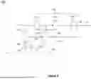

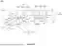


Sources:
- United States Patent and Trademark Office - verify current appl. status at the USPTO↗
Similar patent applications:
- » 20080282684
Apparatus, system, and method for engine-generated heat utilization in a NO-adsorber aftertreatment system - » 20140101286
Apparatus and method for controlling heating, cooling, and refrigeration sensor systems utilizing the wireless cloud - » 20230052253
APPARATUS, SYSTEMS AND METHODS FOR MANAGEMENT OF RAW WATER AND EMISSIONS UTILIZING HEAT AND/OR PRESSURE ENERGY WITHIN COMBUSTION GAS SOURCES - » 20160215930
Apparatus, system and method for the capture, utilization and sendout of latent heat in boil off gas onboard a cryogenic storage vessel - » 20190203884
Apparatus, system and method for the capture, utilization and sendout of latent heat in boil off gas onboard a cryogenic storage vessel - » 20200109817
APPARATUS, SYSTEM AND METHOD FOR THE CAPTURE, UTILIZATION AND SENDOUT OF LATENT HEAT IN BOIL OFF GAS ONBOARD A CRYOGENIC STORAGE VESSEL - » 20210114897
Apparatus, systems and methods for management of raw water and emissions utilizing heat and/or pressure energy within combustion gas sources - » 20180215632
APPARATUS, SYSTEMS AND METHODS FOR MANAGEMENT OF RAW WATER AND EMISSIONS UTILIZING HEAT AND/OR PRESSURE ENERGY WITHIN COMBUSTION GAS SOURCES - » 20190202713
APPARATUS, SYSTEMS AND METHODS FOR MANAGEMENT OF RAW WATER AND EMISSIONS UTILIZING HEAT AND/OR PRESSURE ENERGY WITHIN COMBUSTION GAS SOURCES - » 20170234564
Method and apparatus for re-heat dehumidification utilizing a variable speed compressor system
Recent applications in this class:
- » 20260168708 2026-06-18
Heat Pump System With Thermal Energy Storage - » 20260160456 2026-06-11
OUTDOOR AIR-TO-AIR HEAT PUMP INSTALLATION WITH THERMALLY INSULATED CONDENSER CHAMBER - » 20260126221 2026-05-07
COMPOSITIONS COMPRISING FLUOROOLEFINS AND NATURAL REFRIGERANTS AND USES THEREOF - » 20260126220 2026-05-07
AN ENERGY SYSTEM COMPRISING A MECHANICAL VAPOR RECOMPRESSION (MVR) UNIT FOR USING THERMAL ENERGY GENERATED BY THE MVR-UNIT, AND A METHOD IN RELATION THERETO - » 20260110464 2026-04-23
BAROCALORIC HEAT PUMPS - » 20260085861 2026-03-26
LOW TEMPERATURE NH3 REFORMING PROCESS COUPLED TO A HEAT PUMP - » 20260078934 2026-03-19
Multi-Temperature Level Heat Pump Water Heaters (HPWH) - » 20260063339 2026-03-05
Acclimatized Liquid Powered Dual Circuit Heat Pump - » 20260063338 2026-03-05
SYSTEM FILLED WITH HYDROGEN ABSORBING ALLOY - » 20260049746 2026-02-19
GROUPED MECHANICAL LIQUID PISTON HEAT PUMP