RADIATOR HEADER ASSEMBLY FOR A VEHICLE
US20260177331A1
2026-06-25
19/427,635
2025-12-19
Smart Summary: A radiator header assembly is a part of a vehicle's cooling system. It has a main piece called a header that has several openings for radiator tubes. Each opening has a special rubber gasket that helps create a tight seal around the tubes. This seal prevents leaks and keeps the cooling system working properly. Overall, the assembly helps ensure the vehicle stays at the right temperature while running. 🚀 TL;DR
Abstract:
A radiator header assembly includes a header defining an interior chamber, the header comprising a plurality of header openings, each opening accommodating a respective radiator tube. The radiator header assembly further includes a plurality of elastomeric gaskets overmolded in the plurality of openings, each gasket including a gasket opening to contact the respective radiator tube to form a seal between the tube and the gasket.
Inventors:
- Joel Berneklev 3 🇸🇪 Göteborg, Sweden
- Rikard HULTHÉN 5 🇸🇪 Stora Höga, Sweden
- Erik DAHL 1 🇸🇪 Linderöd, Sweden
- Bengt LYSELL 1 🇸🇪 Häljarp, Sweden
- Tiago ROSSO 1 🇸🇪 Göteborg, Sweden
Applicant:
Interested in similar patents?
Get notified when new applications in this technology area are published.
Classification:
F28F9/0226 » CPC main
Casings; Header boxes; Auxiliary supports for elements; Auxiliary members within casings; Header boxes; End plates; Arrangements for sealing end plates into casing or header box; Header box sub-elements; Header boxes formed by sealing end plates into covers with resilient gaskets
F28F9/14 » CPC further
Casings; Header boxes; Auxiliary supports for elements; Auxiliary members within casings; Header boxes; End plates; Arrangements for sealing elements into header boxes or end plates by dismountable joints by force-joining
F28F9/02 IPC
Casings; Header boxes; Auxiliary supports for elements; Auxiliary members within casings Header boxes; End plates
Description
CROSS REFERENCE TO RELATED APPLICATIONS
This application claims priority to European Patent Application No. 24221810, filed on Dec. 19, 2024, the disclosure and content of which is incorporated by reference herein in its entirety.
TECHNICAL FIELD
The disclosure relates generally to a radiator for a vehicle. In particular aspects, the disclosure relates to a radiator header assembly for a vehicle. The disclosure can be applied to heavy-duty vehicles, such as trucks, buses, and construction equipment, among other vehicle types. Although the disclosure may be described with respect to a particular vehicle, the disclosure is not restricted to any particular vehicle.
BACKGROUND
Vehicle radiators, including charge air coolers, oil coolers, marine coolers, etc., may be used in a coolant system of a vehicle to transfer heat rejected from the powertrain to the ambient air, e.g., heat from internal combustion engines (ICEs), fuel cells, electric motors, inverters, batteries, etc.
In many conventional radiators, large temperature differences between hot side and cold side components may cause uneven thermal expansion of different components, which may in turn lead to mechanical stresses on those components and connections among different components. In addition, many radiators, such as Fuel Cell Electric Vehicle (FCEV) radiators, may have higher cleanliness specifications, which may be difficult to achieve with conventional radiators arrangements. There is a need for a radiator header assembly that addresses these and other technical problems.
SUMMARY
According to a first aspect of the disclosure, a radiator header assembly includes a header defining an interior chamber, the header comprising a plurality of header openings, each opening accommodating a respective radiator tube, and a plurality of elastomeric gaskets overmolded in the plurality of openings, each gasket comprising a gasket opening to contact the respective radiator tube to form a seal between the tube and the gasket. The first aspect of the disclosure may seek to allow for non-uniform thermal expansion of the tubes. A technical benefit may include reducing mechanical stresses on the header due to this non-uniform thermal expansion.
Optionally in some examples, including in at least one preferred example, each gasket is vulcanized to the header.
Optionally in some examples, including in at least one preferred example, each gasket is vulcanized to each respective tube.
Optionally in some examples, including in at least one preferred example, each gasket further comprises an internal flange portion to inhibit longitudinal movement of the gasket in a longitudinal direction away from the interior chamber and an external flange portion to inhibit longitudinal movement of the gasket in the longitudinal direction into the interior chamber.
Optionally in some examples, including in at least one preferred example, each gasket further comprises an inward facing ridge in the gasket opening to maintain the seal between the tube and the gasket during longitudinal movement of the tube with respect to the header.
Optionally in some examples, including in at least one preferred example, each ridge is angled inwardly toward the interior chamber to accommodate insertion of the tube into the gasket in a longitudinal direction into the interior chamber and to inhibit movement of the tube in the longitudinal direction out of the interior chamber.
Optionally in some examples, including in at least one preferred example, the radiator header assembly further includes at least one unitary elastomeric membrane comprising the plurality of gaskets.
Optionally in some examples, including in at least one preferred example, the radiator header assembly further includes at least one rigid member in the interior chamber of the header, each rigid member arranged between at least one adjacent pair of gaskets to inhibit movement of the gaskets with respect to the header.
Optionally in some examples, including in at least one preferred example, the header further comprises a floor member comprising the plurality of header openings, and a shell member coupled to the floor member to define the interior chamber.
Optionally in some examples, including in at least one preferred example, the interior chamber comprises a hot side chamber in fluid communication with a first subset of the plurality of tubes and a cold side chamber in fluid communication with a second subset of the plurality of tubes.
Optionally in some examples, including in at least one preferred example, the radiator header assembly further includes a plurality of threaded members to secure a portion of the shell member to a portion of the floor member.
Optionally in some examples, including in at least one preferred example, the plurality of threaded members are arranged between the hot side chamber and the cold side chamber to define a separation wall between the hot side chamber and the cold side chamber.
According to a second aspect of the disclosure a method of forming a radiator header assembly includes providing a header defining an interior chamber, the header comprising a plurality of header openings, and overmolding a plurality of elastomeric gaskets in the plurality of header openings, each gasket comprising a gasket opening to contact a respective radiator tube inserted into an interior chamber of the header to form a seal between the tube and the gasket. The second aspect of the disclosure may seek to allow for non-uniform thermal expansion of the tubes. A technical benefit may include reducing mechanical stresses on the header due to this non-uniform thermal expansion.
Optionally in some examples, including in at least one preferred example, the method further includes vulcanizing each gasket to the header.
Optionally in some examples, including in at least one preferred example, the method further includes inserting the plurality of tubes into the plurality of gasket openings to form the seals therebetween.
Optionally in some examples, including in at least one preferred example, the method further includes vulcanizing each gasket to each respective tube.
Optionally in some examples, including in at least one preferred example, the method further includes arranging at least one rigid member in the interior chamber of the header, each rigid member arranged between at least one adjacent pair of gaskets to inhibit movement of the gaskets with respect to the header.
Optionally in some examples, including in at least one preferred example, the header further comprises a floor member comprising the plurality of header openings, and a shell member coupled to the floor member to define the hot side chamber and the cold side chamber.
Optionally in some examples, including in at least one preferred example, the method further includes securing a portion of the floor member to a portion of the shell member with a plurality of threaded members.
Optionally in some examples, including in at least one preferred example, the interior chamber comprises a hot side chamber in fluid communication with a first subset of the plurality of tubes and a cold side chamber in fluid communication with a second subset of the plurality of tubes, and the plurality of threaded members are arranged between the hot side chamber and the cold side chamber to define a separation wall between the hot side chamber and the cold side chamber.
The disclosed aspects, examples (including any preferred examples), and/or accompanying claims may be suitably combined with each other as would be apparent to anyone of ordinary skill in the art. Additional features and advantages are disclosed in the following description, claims, and drawings, and in part will be readily apparent therefrom to those skilled in the art or recognized by practicing the disclosure as described herein.
BRIEF DESCRIPTION OF THE DRAWINGS
Examples are described in more detail below with reference to the appended drawings.
FIG. 1 is an exemplary vehicle with a radiator assembly, according to an example.
FIGS. 2A and 2B are perspective and cross-sectional views of a radiator assembly, according to the prior art.
FIG. 3 is a cross sectional view of an exemplary radiator header assembly, according to an example.
FIG. 4 is a cross sectional view of a portion of an exemplary radiator header assembly, including overmolded elastomeric gaskets, according to an example.
FIG. 5 is a cross sectional view of a portion of an exemplary radiator header assembly, including rigid members disposed between adjacent pairs of gaskets, according to an example.
FIG. 6 is a cross sectional view of an elastomeric gasket, including inward facing ridges in the gasket opening, according to an example.
FIG. 7 is a cross sectional view of an elastomeric gasket, including inwardly angled inward facing ridges in the gasket opening, according to an example.
FIG. 8 is a flow chart of an exemplary method of forming a radiator header assembly, according to an example.
DETAILED DESCRIPTION
The detailed description set forth below provides information and examples of the disclosed technology with sufficient detail to enable those skilled in the art to practice the disclosure.
FIG. 1 is an exemplary vehicle 10 with a radiator assembly 100, according to an example. The vehicle 10, which is a heavy truck in this embodiment, includes a cab 102 on a chassis 104. An engine 106, which is an Internal Combustion Engine (ICE) in this example, includes a radiator assembly 100 for providing cooling fluid to the engine 106 and other components, receiving heated cooling fluid from the engine 106 and other components, transferring the heat from the heated cooling fluid, and returning the now-cooled cooling fluid to the engine 106 and other components.
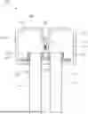
FIGS. 2A and 2B are perspective and cross-sectional views of a radiator assembly 200, according to the prior art. A conventional radiator assembly 200 may include a plurality of radiator tubes 216 connected between a header 208 and a turn chamber 218. The header 208 may define an interior chamber 210 that includes a hot side 212 and a cold side 214. The hot side 212 receives heated cooling fluid and directs the fluid through a subset of radiators tubes 216 on the hot side 212, through the turn chamber 218, and through a subset of tubes 216 on the cold side 214. The radiators tubes absorb heat from the heated cooling fluid and transfer the heat to the ambient air, such that the cooling fluid is significantly cooled by the time it reaches the cold side 214 of the header 208.
Different types of vehicles have different cooling requirements. For example, a Fuel Cell Electric Vehicle (FCEV) may require significantly more cooling capacity, e.g., larger and more numerous radiators, than ICE vehicles. In addition, the manufacturing process for FCEV radiators may be more complex and may include a time-consuming cleaning stage, which significantly increases costs for FCEV radiators.
In some conventional radiators, the radiator tubes 216 may be brazed and/or otherwise fixed to the header 208. However, the tubes 216 on the hot side 212 may experience significantly more thermal expansion than the tubes 216 on the cold side, which may put stress on the brazed header connection, which may result in cracks at the joints between the header 208 and the tubes 216.
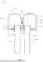
To address this and other technical problems, FIG. 3 is a cross sectional view of an exemplary radiator header assembly 300, according to an example. In this example, the radiator header assembly 300 may include a header 308 defining an interior chamber 310. The header 308 may include a plurality of header openings 320, with each opening 320 accommodating a respective radiator tube 316.
The radiator header assembly 300 may further include a plurality of elastomeric gaskets 322 corresponding to the plurality of openings 320. Each gasket 322 may include a gasket opening 324 to contact the respective radiator tube 316 to form a seal between the tube 316 and the gasket 322. In this example, each gasket 322 is vulcanized to the header 308, and is also vulcanized to each respective tube 316. In this example, the tubes 316 have a circular cross section, but it should be understood that other shapes, such as oval, elliptical, flat, etc., may be used, as desired. In some examples, the tubes 316 may include a plurality of microchannels, which may enhance heat transfer from the cooling fluid to the tube 316 by increasing the internal surface area within the tube 316. One advantage of this arrangement is that the tubes 316 may be permanently and/or semi-permanently attached to the header 308 while also allowing for non-uniform thermal expansion of the different tubes 316 in the longitudinal direction, thereby maintaining the seals therebetween without inducing excessive mechanical stress on the assembly 300. This arrangement may also allow for non-uniform thermal expansion of the tubes in a radial direction, but this does not present as great a problem in this context. For example, radial thermal expansion will be less than longitudinal expansion due to the high length-to-diameter ratio of the tubes 316. In addition, the header assembly may be able to better resist compression force that may be caused by thermal expansion in the radial direction, in comparison to the shear forces that may be caused by non-uniform longitudinal expansion of the tubes 316.
In this example, the header 308 includes a floor member 328 that includes the plurality of header openings 320, and a shell member 326 coupled to the floor member 328 to define the interior chamber 310. In this example, the interior chamber 310 includes a hot side chamber 312 in fluid communication with a first subset 330 of the plurality of tubes 316 and a cold side chamber 314 in fluid communication with a second subset 332 of the plurality of tubes 316.
In this example, a plurality of threaded members 334, e.g., screws, bolts, etc., secure a portion of the shell member 326 to a portion of the floor member 328. In this example, the plurality of threaded members 334 are arranged between the hot side chamber 312 and the cold side chamber 314 to define a separation wall 336 between the hot side chamber 312 and the cold side chamber 314. One advantage of this arrangement is that the threaded members provide additional structural integrity to the header 308 to prevent bending of the header components due to the temperature differential between the hot side chamber 312 and the cold side chamber 314. Unlike other securing arrangements such as welding, threaded members does not introduce contaminants into the header that might require a cleaning process.
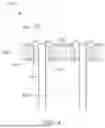
FIG. 4 is a cross sectional view of a portion of an exemplary radiator header assembly 400, including overmolded elastomeric gaskets 422, according to an example. The tubes 416 in this example may be arranged on either side (i.e., hot side or cold side) or both sides of the interior chamber 410, as desired. In this example, each gasket 422 is overmolded into each header opening 420 in the floor member 428, such that the tubes 416 extending through the gasket openings 424 into the interior chamber 410 may be more securely retained therein. In this example, each gasket 422 further includes an internal flange portion 438 to inhibit longitudinal movement of the gasket 422 in a longitudinal direction away from the interior chamber 410, and an external flange portion 440 to inhibit longitudinal movement of the gasket 422 in the longitudinal direction into the interior chamber 410.
FIG. 5 is a cross sectional view of a portion of an exemplary radiator header assembly 500, including rigid members 544 disposed between adjacent pairs of gaskets 522, according to an example. As with FIG. 4, the tubes 516 in this example may be arranged on either side (i.e., hot side or cold side) or both sides of the interior chamber 510, as desired. In this example, at least one unitary elastomeric membrane 542 comprising the plurality of gaskets 522 is provided. This arrangement allows for the tubes 516 to move longitudinally (i.e., in a z-direction) through the header openings 520 in the floor member 528 without necessarily contacting the header openings 520, while also engaging the gasket openings 524 to maintain a seal for the interior chamber 510.
Additionally, the rigid members 544 shown in FIG. 5, may inhibit movement of the gaskets 522 with respect to the floor member 528. For example, the membrane 542 and gaskets 522 may not be directly attached to the floor member 528, to permit some longitudinal movement of the gaskets 522 based on longitudinal thermal expansion of the tubes 516. Meanwhile, the rigid members 544 may inhibit movement of the gaskets 522 and tubes 516 in one or more directions, such as longitudinal movement and/or lateral movement for example. In some embodiments, the rigid member(s) 544 may be part of a unitary lock plate that covers a row of tubes 516, providing structural support and contact pressure between the tube 516 and the gasket 522 while still allowing for sufficient movement of the tube 516 in the longitudinal direction. This arrangement may be particularly advantageous for arrangements using non-circular tubes 516, which may otherwise have non-uniform contact pressure with respect to the gasket 522.
In addition, in this example, a dust elastomer 546 may be provided to inhibit ingress of dust and other contaminants into the interior chamber 510, thereby providing another sealing layer to separate the interior chamber 510 from the ambient air. In some examples, the dust elastomer 546 may be glued, vulcanized, and/or otherwise fastened to the floor member 528.
FIG. 6 is a cross sectional view of an elastomeric gasket 622 and floor member 628, including inward facing ridges 648 in the gasket opening 624, according to an example. In this example, each gasket 622 includes one or more inward facing ridges 648 in the gasket opening 624 to maintain the seal between the tube 616 and the gasket 622 during longitudinal movement of the tube with respect to the header.
FIG. 7 is a cross sectional view of an elastomeric gasket 722 and floor member 728, including inwardly angled inward facing ridges 750 in the gasket opening 724, according to an example. In this example, each ridge is angled inwardly toward the interior chamber 710 to accommodate insertion of the tube 716 into the gasket 722 in a longitudinal direction into the interior chamber 710. After insertion, the inwardly angled inward facing ridges 750 also act to inhibit movement of the tube 716 in the longitudinal direction out of the interior chamber 710.
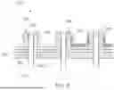
FIG. 8 is a flow chart of operations 800 an exemplary method of forming a radiator header assembly, according to an example. The operations 800 may include providing a header defining an interior chamber, the header comprising a plurality of header openings (Block 802). The operations 800 may further include overmolding a plurality of elastomeric gaskets in the plurality of header openings, each gasket comprising a gasket opening to contact a respective radiator tube inserted into an interior chamber of the header to form a seal between the tube and the gasket (Block 804).
Optionally, the operations 800 may further include vulcanizing each gasket to the header (Block 806). Optionally, the operations 800 may further include inserting the plurality of tubes into the plurality of gasket openings to form the seals therebetween (Block 808), and may further include vulcanizing each gasket to each respective tube (Block 810). Optionally, the operations 800 may further include arranging at least one rigid member in the interior chamber of the header, each rigid member arranged between at least one adjacent pair of gaskets to inhibit movement of the gaskets with respect to the header (Block 812). In some embodiments, each rigid member may inhibit longitudinal movement, lateral movement, or both, as desired. Optionally, the operations 800 may further include securing a portion of the floor member to a portion of the shell member with a plurality of threaded members (Block 814).
Additional examples include:
Example 1. A radiator header assembly comprising:
-
- a header defining an interior chamber, the header comprising a plurality of header openings, each opening accommodating a respective radiator tube; and
- a plurality of elastomeric gaskets overmolded in the plurality of openings, each gasket comprising a gasket opening to contact the respective radiator tube to form a seal between the tube and the gasket.
Example 2. The radiator header assembly of claim 1, wherein each gasket is vulcanized to the header.
Example 3. The radiator header assembly of any of claims 1 and 2, wherein each gasket is vulcanized to each respective tube.
Example 4. The radiator header assembly of any preceding claim, wherein each gasket further comprises an internal flange portion to inhibit longitudinal movement of the gasket in a longitudinal direction away from the interior chamber and an external flange portion to inhibit longitudinal movement of the gasket in the longitudinal direction into the interior chamber.
Example 5. The radiator header assembly of any preceding claim, wherein each gasket further comprises an inward facing ridge in the gasket opening to maintain the seal between the tube and the gasket during longitudinal movement of the tube with respect to the header.
Example 6. The radiator header assembly of claim 5, wherein each ridge is angled inwardly toward the interior chamber to accommodate insertion of the tube into the gasket in a longitudinal direction into the interior chamber and to inhibit movement of the tube in the longitudinal direction out of the interior chamber.
Example 7. The radiator header assembly of any preceding claim, further comprising at least one unitary elastomeric membrane comprising the plurality of gaskets.
Example 8. The radiator header assembly of any preceding claim, further comprising at least one rigid member in the interior chamber of the header, each rigid member arranged between at least one adjacent pair of gaskets to inhibit movement of the gaskets with respect to the header.
Example 9. The radiator header assembly of any preceding claim, wherein the header further comprises:
-
- a floor member comprising the plurality of header openings; and
- a shell member coupled to the floor member to define the interior chamber.
Example 10. The radiator header assembly claim 9, wherein the interior chamber comprises a hot side chamber in fluid communication with a first subset of the plurality of tubes and a cold side chamber in fluid communication with a second subset of the plurality of tubes.
Example 11. The radiator header assembly of any of claims 9 and 10, further comprising a plurality of threaded members to secure a portion of the shell member to a portion of the floor member.
Example 12. The radiator header assembly of claim 11 when dependent from claim 10, wherein the plurality of threaded members are arranged between the hot side chamber and the cold side chamber to define a separation wall between the hot side chamber and the cold side chamber.
Example 13. A method of forming a radiator header assembly comprising:
-
- providing a header defining an interior chamber, the header comprising a plurality of header openings; and
- overmolding a plurality of elastomeric gaskets in the plurality of header openings, each gasket comprising a gasket opening to contact a respective radiator tube inserted into an interior chamber of the header to form a seal between the tube and the gasket.
Example 14. The method of claim 13, further comprising vulcanizing each gasket to the header.
Example 15. The method of any of claims 13 and 14, further comprising inserting the plurality of tubes into the plurality of gasket openings to form the seals therebetween.
Example 16. The method of any of claims 13-15, further comprising vulcanizing each gasket to each respective tube.
Example 17. The method of any of claims 13-16, further comprising arranging at least one rigid member in the interior chamber of the header, each rigid member arranged between at least one adjacent pair of gaskets to inhibit movement of the gaskets with respect to the header.
Example 18. The method of any of claims 13-17, wherein the header further comprises:
-
- a floor member comprising the plurality of header openings; and
- a shell member coupled to the floor member to define the hot side chamber and the cold side chamber.
Example 19. The method of claim 18, further comprising:
-
- securing a portion of the floor member to a portion of the shell member with a plurality of threaded members.
Example 20. The method of claim 19, wherein the interior chamber comprises a hot side chamber in fluid communication with a first subset of the plurality of tubes and a cold side chamber in fluid communication with a second subset of the plurality of tubes, and
-
- wherein the plurality of threaded members are arranged between the hot side chamber and the cold side chamber to define a separation wall between the hot side chamber and the cold side chamber.
The terminology used herein is for the purpose of describing particular aspects only and is not intended to be limiting of the disclosure. As used herein, the singular forms “a,” “an,” and “the” are intended to include the plural forms as well, unless the context clearly indicates otherwise. As used herein, the term “and/or” includes any and all combinations of one or more of the associated listed items. It will be further understood that the terms “comprises,” “comprising,” “includes,” and/or “including” when used herein specify the presence of stated features, integers, actions, steps, operations, elements, and/or components, but do not preclude the presence or addition of one or more other features, integers, actions, steps, operations, elements, components, and/or groups thereof.
It will be understood that, although the terms first, second, etc., may be used herein to describe various elements, these elements should not be limited by these terms. These terms are only used to distinguish one element from another. For example, a first element could be termed a second element, and, similarly, a second element could be termed a first element without departing from the scope of the present disclosure.
Relative terms such as “below” or “above” or “upper” or “lower” or “horizontal” or “vertical” may be used herein to describe a relationship of one element to another element as illustrated in the Figures. It will be understood that these terms and those discussed above are intended to encompass different orientations of the device in addition to the orientation depicted in the Figures. It will be understood that when an element is referred to as being “connected” or “coupled” to another element, it can be directly connected or coupled to the other element, or intervening elements may be present. In contrast, when an element is referred to as being “directly connected” or “directly coupled” to another element, there are no intervening elements present.
Unless otherwise defined, all terms (including technical and scientific terms) used herein have the same meaning as commonly understood by one of ordinary skill in the art to which this disclosure belongs. It will be further understood that terms used herein should be interpreted as having a meaning consistent with their meaning in the context of this specification and the relevant art and will not be interpreted in an idealized or overly formal sense unless expressly so defined herein.
It is to be understood that the present disclosure is not limited to the aspects described above and illustrated in the drawings; rather, the skilled person will recognize that many changes and modifications may be made within the scope of the present disclosure and appended claims. In the drawings and specification, there have been disclosed aspects for purposes of illustration only and not for purposes of limitation, the scope of the disclosure being set forth in the following claims.
Claims
What is claimed is:1. A radiator header assembly comprising:
a header defining an interior chamber, the header comprising a plurality of header openings, each opening accommodating a respective radiator tube; and
a plurality of elastomeric gaskets overmolded in the plurality of openings, each gasket comprising a gasket opening to contact the respective radiator tube to form a seal between the tube and the gasket.
2. The radiator header assembly of claim 1, wherein each gasket is vulcanized to the header.
3. The radiator header assembly of claim 1, wherein each gasket is vulcanized to each respective tube.
4. The radiator header assembly of claim 1, wherein each gasket further comprises an internal flange portion to inhibit longitudinal movement of the gasket in a longitudinal direction away from the interior chamber and an external flange portion to inhibit longitudinal movement of the gasket in the longitudinal direction into the interior chamber.
5. The radiator header assembly of claim 1, wherein each gasket further comprises an inward facing ridge in the gasket opening to maintain the seal between the tube and the gasket during longitudinal movement of the tube with respect to the header.
6. The radiator header assembly of claim 5, wherein each ridge is angled inwardly toward the interior chamber to accommodate insertion of the tube into the gasket in a longitudinal direction into the interior chamber and to inhibit movement of the tube in the longitudinal direction out of the interior chamber.
7. The radiator header assembly of claim 1, further comprising at least one unitary elastomeric membrane comprising the plurality of gaskets.
8. The radiator header assembly of claim 1, further comprising at least one rigid member in the interior chamber of the header, each rigid member arranged between at least one adjacent pair of gaskets to inhibit movement of the gaskets with respect to the header.
9. The radiator header assembly of claim 1, wherein the header further comprises:
a floor member comprising the plurality of header openings; and
a shell member coupled to the floor member to define the interior chamber.
10. The radiator header assembly of claim 9, wherein the interior chamber comprises a hot side chamber in fluid communication with a first subset of the plurality of tubes and a cold side chamber in fluid communication with a second subset of the plurality of tubes.
11. The radiator header assembly of claim 10, further comprising a plurality of threaded members to secure a portion of the shell member to a portion of the floor member.
12. The radiator header assembly of claim 11, wherein the plurality of threaded members are arranged between the hot side chamber and the cold side chamber to define a separation wall between the hot side chamber and the cold side chamber.
13. A method of forming a radiator header assembly comprising:
providing a header defining an interior chamber, the header comprising a plurality of header openings; and
overmolding a plurality of elastomeric gaskets in the plurality of header openings, each gasket comprising a gasket opening to contact a respective radiator tube inserted into an interior chamber of the header to form a seal between the tube and the gasket.
14. The method of claim 13, further comprising vulcanizing each gasket to the header.
15. The method of claim 13, further comprising inserting the plurality of tubes into the plurality of gasket openings to form the seals therebetween.
Images & Drawings included:


Sources:
- United States Patent and Trademark Office - verify current appl. status at the USPTO↗
Recent applications in this class:
- » 20240102746 2024-03-28
A HEADER TANK ASSEMBLY - » 20230341194 2023-10-26
Heat exchanger having header structure for dispersing thermal stress - » 20230194192 2023-06-22
AUTOMOTIVE LOCKING RING AND INTERCOOLER WITH CARBONFIBER END TANK - » 20220325964 2022-10-13
A HEADER-TANK ASSEMBLY - » 20210293493 2021-09-23
Heat exchanger - » 20210293492 2021-09-23
Collector box, sealing means and corresponding heat exchanger - » 20210285732 2021-09-16
Collector plate, corresponding header box and corresponding heat exchanger - » 20210025661 2021-01-28
Heat exchanger - » 20200271398 2020-08-27
Integrated heat exchanger - » 20200166296 2020-05-28
A HEAT EXCHANGER