ARCHERY GRIPS AND STABILIZERS
US20260177344A1
2026-06-25
19/432,830
2025-12-24
Smart Summary: Grips and stabilizers are designed to enhance the experience of shooting a bow. They help reduce vibrations and small movements that can affect accuracy when shooting. The grips can pivot, allowing them to absorb some of the movement from the bow. Stabilizers can also pivot to help minimize these small movements. By combining these features, the setup aims to improve stability and performance during archery. 🚀 TL;DR
Abstract:
Grips, stabilizers, bows, and combinations thereof are disclosed to improve user shooting experience. Pivoting grips can be used to isolate vibration or other small movement from the bow riser and other components during shooting. Pivoting stabilizers can also be used to attenuate small movements. Grip-mounted stabilizers can be utilized with one or both of the grip and stabilizer including pivots or similar movable parts to reduce or attenuate transients experienced by the bow during shooting.
Applicant:
Interested in similar patents?
Get notified when new applications in this technology area are published.
Classification:
F41B5/1426 » CPC main
Bows; Crossbows; Details of bows; Accessories for arc shooting; Details of bows; Bow stabilisers or vibration dampers
F41B5/14 IPC
Bows; Crossbows Details of bows; Accessories for arc shooting
Description
CROSS-REFERENCE TO RELATED APPLICATIONS
This patent application claims priority to and the benefit of pending provisional patent application 63/738,618 filed Dec. 24, 2024, which is incorporated herein by reference in its entirety.
FIELD
The subject matter disclosed herein generally relates to archery equipment, and more particularly relates to grips and stabilizers that reduce transients and/or provide preferred user experience.
BACKGROUND
Shooting, and similar activities, involve myriad variables to deliver a projectile to a desired location. Many parameters beyond proper aiming influence both the accuracy and precision of the target. Some of these involve vibration inherent to the system, movement of the shooter, and other transients.
SUMMARY
In embodiments, a grip for a bow can be provided with limited degrees of freedom to reduce vibration or other transients during shooting.
In embodiments, a pivoting grip for a bow is provided for use with a bow or other device.
In embodiments, a stabilizer for a bow can be mounted to a grip described herein.
In embodiments, a pivoting grip for a bow can be tensioned for stiffness.
Other portions of this disclosure will describe various alternative and complementary embodiments. As such, the foregoing summary is provided for purposes of example only and should not be deemed in any way to limit the scope or spirit of the disclosure or claims.
BRIEF DESCRIPTION OF THE DRAWINGS
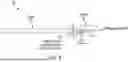
FIG. 1 depicts a perspective of a compound bow.
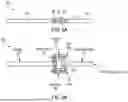
FIG. 2A depicts a perspective of a compound bow with an embodiment of an invention disclosed herein installed.
FIG. 2B depicts a side view of a compound bow with an embodiment of an invention disclosed herein installed.
FIG. 2C depicts a perspective of components of an invention disclosed herein.
FIG. 2D depicts a side view of components of an invention disclosed herein at twice the scale shown in FIG. 2C.
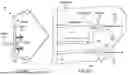
FIG. 3A illustrates a side view of a compound bow with an embodiment of an invention disclosed herein installed.
FIG. 3B illustrates a top view of a compound bow with an embodiment of an invention disclosed herein installed.
FIG. 3C illustrates a top view of components of an invention disclosed herein.
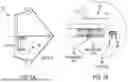
FIG. 4 illustrates components of an invention disclosed herein.
FIG. 5A illustrates a top view of components of an invention disclosed herein.
FIG. 5B illustrates a side view of components of an invention disclosed herein.
FIG. 6 illustrates views of components of an invention disclosed herein.
FIG. 7 illustrates views of components of an invention disclosed herein.
FIG. 8 illustrates views of components of an invention disclosed herein.
FIG. 9 illustrates views of components of an invention disclosed herein.
FIG. 10 illustrates views of components of an invention disclosed herein.
FIG. 11 illustrates views of components of an invention disclosed herein.
Other portions of this disclosure will describe various alternative and complementary embodiments. As such, the foregoing brief description is provided for purposes of example only and should not be deemed in any way to limit the scope or spirit of the disclosure or claims.
DETAILED DESCRIPTION
Aspects herein relate to various grips and stabilizers for modifying the dynamics of archery equipment. Innovations disclosed herein can include bow grips that pivot laterally (or in other dimensions), relative to the bow, and in which a stabilizer can be attached to such grips. Such innovations can change bow dynamics by smoothing transients, reducing movement of the sight when aiming a bow and reducing or changing vibration of the bow during and after release of the arrow. Aspects described herein facilitating such improvements can include (but are not limited to) frictionless pivots (or pivots that are nearly frictionless, have low friction, or have a known amount of friction or friction below a particular threshold), a stabilizer attached to a pivoting grip (rather than a fixed grip or other part of a bow), center-biasing tension from components holding the pivots together (e.g., bolts, other fasteners or members), and tune-able resistance of the pivots (e.g., ability to adjust the effective stiffness of the stabilizer).
In embodiments, pivot in-line of stabilizers can facilitate adjustment of the effective stiffness based on user preference or measured performance at different stiffnesses (which may be idiosyncratically based on a particular bow setup, arrow, arrowhead, fletching, release, user, et cetera). In embodiments, tension adjustment can be facilitated by rotating a bolt or other fastener holding the joint together. The size of the bolt (in addition to the extent to which it is tightened) also influences tension and can accordingly be varied to provide desired performance in various embodiments or variants. In embodiments, graduations may be depicted on one or more components to facilitate repeatable tensioning.
Pivots disclosed herein allow essentially frictionless pivoting. Unlike a hinge, which provides no resistance to pivoting motion (other than friction), the pivots described herein are biased to restore the elements coupled therewith to the original alignment. Put another way, pivots can be arranged such that they tend to “straighten out” absent external forces, and in bolts or similar forces described herein can further resist the pivot being out of alignment. A pivot can be in alignment when a centerlines through the elements on either side of the pivot is substantially aligned or parallel, and a pivot can be out of alignment when a centerlines through the elements on either side of the pivot is askew. Embodiments herein can utilize a bolt (or other fastener or member) connecting both sides of the pivot such that, when the pivot is flexed, the bolt is bent slightly. This provides resistance to the flexing and pulls the pivot towards the original (e.g., neutral) alignment of system elements. Embodiments herein permit left-and right-flexing and can be vertically rigid. This can be achieved by using a (relatively) flexible bolt in conjunction with a rigid pivot point. In embodiments the rigid pivot point can be provided using a radiused extension contacting a stabilizer.
Embodiments illustrated provide frictionless resistance to flexing at the pivot, with said resistance adjusting continuously as the pivot flexes one direction or another. The effective resistance to flexing changes when the bolt is tightened because the radiused extension is held tighter against the stabilizer. Tightening the bolt makes the pivot less flexible and provides more resistance to flexing because instead of using the flex of the bolt to resist movement the bolt is put under tension. Conceptually, in this way, even a string connecting the two would accomplish the same resistance to flexing based on the tension put into the string. As such, adjusting the tension applied between the radiused extension and the stabilizer is what adjusts the effective stiffness of the stabilizer.
The position of the pivot can be selectable, and users can select different extension lengths and stabilizer lengths to tune the system for the particular application and desired performance.
In alternative embodiments, aspects herein can be designed for installation to an existing bow or designed integrally into a bow. In embodiments, the position(s) of pivots with respect to other elements of the bow can be adjusted according to a user's preference.
In embodiments, the placement of the grip can be adjustable to match a particular user preference or to facilitate performance testing in different positions to tune the grip for performance and/or comfort.
In embodiments, a pivot can be provided at the end of a stabilizer, or anywhere on the bow, for vibration dampening without rubber (or with rubber in alternative arrangements). In embodiments, the pivot can be designed to flex laterally; and in alternative embodiments alternative or additional degrees of freedom can be provided to facilitate absorption of vibration in other manners.
While aspects herein are depicted or described in connection with compound bows, it will be understood by those of skill in the art that innovations disclosed herein can be implemented in connection with other bows such as traditional bows (e.g., longbows, flat bows, recurve bows, horse bows, and others). Further, the principles and components herein can be modified for integration with or into many other devices having handheld grips, including but not limited to crossbows, firearms, slingshots, et cetera. In all instances where a bow (or more specific device) is described, it will be understood by those in the art that other such devices can be substituted without departing from the scope or spirit of the innovation.
Further, while aspects herein depict and refer to frictionless pivots, it is understood that alternative components can be used to achieve comparable effects without departing from the scope or spirit of the innovation. For example, alternative pivot designs, bearings, or other components can be used without departing from the scope or spirit of the innovation. Further, pivots can be reinforced or designed to reduce or eliminate certain degrees of freedom (e.g., reducing or eliminating vertical/y axis translation, reducing or eliminating x- or z-axis translation) without departing from the scope or spirit of the innovation.
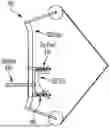
FIG. 1 depicts a perspective of a compound bow. Particularly, FIG. 1 sets forth a coordinate system for describing compound bows spatially. As described, the y axis describes a top-to-bottom axis of the bow along its straight-line length, parallel to (or defined by) a line between the cams (in compound bows where the cams are symmetrically aligned on the limbs when the bow is upright and level). The z axis describes a front-to-back axis of the bow, such as how the arrow is pushed when released, parallel to (or defined by) a line between the nock and arrow rest (in compound bows where the nock and arrow rest are symmetrically aligned when the bow is upright and level). The x axis is perpendicular to the y and z axes, parallel to (or defined by) a line through the width of bow components. Rotation around the x axis is referred to herein as pitch; rotation around the y axis is referred to herein as yaw; and rotation around the z axis is referred to herein as cant.
Bow 100 can include riser 110, grip 120, stabilizer 140, top limb 132, bottom limb 134, top cam 152, and bottom cam 154, among other parts.
Transients or aiming errors can be aligned to each axis, such that aiming errors or transients impacting the flight of the arrow can be referred to as “sway” when occurring translationally along the X-axis, “jump” when occurring translationally along the Y-axis, “push” when occurring along translationally the Z-axis, “pitch” when occurring rotationally around the X-axis, “yaw” when occurring rotationally around the Y-axis, and “cant” when occurring rotationally around the Z-axis.
When shooting a typical compound bow 100 such as that of FIG. 1, the shooter's hand wraps around the grip 120, such that their movements can impart sway, jump, push, pitch, yaw, and/or cant. All of these can cause an arrow to fly other than as intended and reduce both accuracy and precision. If such movements can be attenuated, or their magnitude reduced, accuracy and/or precision can be improved.
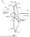
FIG. 2A depicts a perspective of a compound bow with an embodiment of an invention disclosed herein installed. Compound bow components are identified, such as the riser, grip. Visible, but not identified, are, e.g., the limbs, cams, and string. An embodiment of a pivoting and stabilized grip disclosed herein installed to the compound bow is also depicted, indicated by callouts to the top pivot, stabilizer, grip, bottom pivot, and riser cutout. FIG. 2B depicts a detailed view of components of the invention seen in FIG. 2A. FIG. 2C depicts a side view of a compound bow with an embodiment of an invention disclosed herein installed. FIG. 2D depicts a detailed view of components of the invention seen in FIG. 2b. Particularly, FIGS. 2B and 2D illustrate a bottom pivot and components coupled thereto for attaching a grip described herein to a bow. As will be understood, the views of 2B and 2D are drawn to different scale.
Bow 200 includes riser 230 which includes riser cutout 270. Because stabilizer 250 is attached to pivot-mounted grip 260, riser cutout 270 permits stabilizer 250 to extend beyond riser 230.
FIGS. 2B and 2D depict in detail bottom pivot assembly 280. Bottom pivot assembly 280 includes riser projection 281, bottom pivot assembly brace 282, bottom pivot bolt 284, bottom pivot 286, and bottom pivot projection 288. Top pivot 240 can include the same structure and assembly.
The grip assembly including grip 260 can be held by the user (with or without contacting stabilizer 250) without contact to riser 230. In this way, transients imparted by the user to the grip can be eliminated or attenuated before being communicated to riser 230, thereby reducing such transients on the larger bow as an arrow is released.
Stabilizer 250, on bow 200 or other embodiments herein, can be mounted at various heights in connection with or in relation to grip 260. In an embodiment, stabilizer 250 can be mounted at a height (whether connected to grip 260, riser 230, or another component) at a midpoint between the top and bottom of grip 260. Alternatively, stabilizer 250 can connect above or below the midpoint, or can be mounted in relation to a center of mass or other calculable point along the length of grip 260.
Bolts 284 and 290 can have flexibility such that they can deflect slightly to permit movement about the pivots of top pivot 240 and bottom pivot 286. Bolts herein can be tightened to increase tension and in doing so increase the stiffness of the pivot through which the bolt passes. It will be understood that while a tighten-able, threaded bolt is used in various embodiments and referenced for ease of description, those of skill in the art can upon review of the disclosures herein understand other mechanisms (fixed or adjustable) to increase or decrease (or provide a predetermined) pivot stiffness without departing from the scope or spirit of the innovation. Components into which bolts (or other members carrying tension) herein are installed are substantially inflexible and, in embodiments, do not materially deflect to ensure tension is imparted to the bolt rather than distributing load through other elements.
While the pivot face of pivot 286 is depicted as arranged on the riser side of riser projection 281, it will be understood by those of skill in the art that the pivot face (or any portion of a pivot or equivalent structure/functional assembly) may be arranged on either side without departing from the scope or spirit of the innovation.
Tensioning a bolt herein can be performed in various manners. In embodiments, a torque wrench or similar apparatus can be used to tension bolts to known and repeatable tensions. In embodiments, bolt tension in top and bottom assemblies is substantially equal. In alternative embodiments, top bolt 290 and bottom bolt 284 can be tensioned to different tensions. In embodiments, knurling can be included on a bolt end to permit hand tightening or loosening. In embodiments, graduated incremental markers can be provided on a bolt head, pivot assembly, and/or other elements to permit for measurement or tracking of bolt turning and corresponding tension.
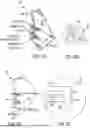
FIGS. 3A and 3B show a bow having a stabilizer described herein attached. FIG. 3C illustrates aspects of the stabilizer including a stabilizer coupled with a radiused extension and a bolt configured to hold the stabilizer against the radiused extension.
Bow 300 includes limb(s) 302, cam(s) 304, string 306 (and/or various cables as used in compound bows), radiused extension 352, pivot 353, and stabilizer 356. Bolt 354 can be used to attach stabilizer 356 to radiused extension 352, and the extent to which bolt 354 is threaded can impart tension on bolt 345 and correspondingly make radius 353 more or less stiff to deflection and correspondingly increase or decrease the amount of motion stabilizer 356 can experience based on forces imparted (e.g., by an archer's movements or other transients).
Bolt 354 can be tightened various ways in embodiments of bow 300, such as by rotating stabilizer 356 with respect to radiused extension 352, tightening or loosening hardware protruding from various elements, using a wrench or driver that is passed within a bore to engage with bolt 354, and various other means in different embodiments.
In embodiments, the stabilizer of FIGS. 3A, 3B, and 3C can be utilized with a V-bar mount or other hardware used for mounting stabilizers in archery equipment without departing from the scope or spirit of the innovation. In such embodiments, the I-bolt used with a V-bar mount can be bolt 354 in a stabilizer including a radius as described herein.
While aspects herein show combinations of grips and stabilizers disclosed herein, it will be appreciated by those of skill in the art that grips disclosed herein may be used without stabilizers, and stabilizers disclosed herein may be used without any particular grip design, without departing from the scope or spirit of the innovations herein.
FIG. 4 illustrates components of an invention disclosed herein. Particularly, FIG. 4 illustrates a stabilizer having a tensioned string or pin to hold a tensioner rigidly and create a pivot. The stabilizer is coupled with an extension and tensioner and has a bow attachment point distal to the direction the stabilizer extends. The tensioner can flex into one or more directions within a cavity of the extension. Degrees of freedom of the tensioner can be controlled using a tensioned string or pin that extends between opposite sides of the extension, which passes through a hole of the tensioner.
Stabilizer 400 of FIG. 4 shows stabilizer section 402, extension 404, tensioner 406, coupling point 408, and tensioned element 410. Tensioned element 410 can be, e.g., one or more bolts, strings, or other mechanisms that can be tightened or loosened to increase or decrease tension. Extension 404 is rigid such that it does not deflect (or materially deflect) based on the tension of tensioned element 410. In this manner, the tension of tensioned element 410 will influence an amount of deflection that tensioner 406 can undergo to permit motion of stabilizer 402.
In embodiments, extension 404 can wrap around tensioner 406. In alternative embodiments, extension 404 can be cutaway as shown and only overlap or cover tensioner 406 about part of its volume.
While stabilizer 400 shows stabilizer 402 as attached to tensioner 406 outside of extension 404, it will be understood that extension 404 may extend to surround at least a portion of stabilizer 404, and dimensions of various components herein can be varied as to their respective sizes in relation to one another without departing from the scope or spirit of the innovation.
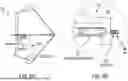
FIGS. 5A and 5B illustrate a two-pivot stabilizer 500 disclosed herein. Particularly, FIGS. 5A and 5B illustrate adjustable stabilizers with two pivots oriented vertically to increase the vertical rigidity (e.g., translation on the y-axis, rotation about the x-axis). As will be appreciated, various pivots or combinations of pivots can be used to control various degrees of freedom such that a stabilizer (or grip) can move in relation to other elements of (or coupled with) a bow.
FIG. 5A and FIG. 5B show, respectively, side and top views respectively of stabilizer 500 including stabilizer section 502, top pivot front housing 504, top pivot 506, top pivot rear housing 508, bolt 510, and radiused extension 512. Front pivot brace 503 and rear pivot brace 509 connect the top and bottom pivots and are configured to connect stabilizer section 502 with radiused extension 512. As discussed elsewhere herein, the radius may appear on either side without departing from the scope or spirit of the innovation.
FIG. 5B shows a side view of stabilizer 500 where bottom pivot 526 and bottom bolt 528 are visible, providing a two-pivot arrangement providing flexibility between extension 512 and stabilizer section 502 that can be tuned to provide stiffer pivots and reduce or prevent flexibility in certain degrees of freedom.
As shown in FIGS. 5A and 5B, various machining can be implemented without departing from the scope or spirit of the innovation. As depicted, the machining provides room for top bolt 510 and bottom bolt 528 to flex, thereby facilitating pivoting. Flex of the bolts can occur between the bolt head and where the threading engages the opposite side of a pivot. Such machining and bores to accommodate bolts can be arranged using front and rear pivot braces as shown, or can be made in radiused extensions, stabilizers, or other elements.
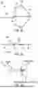
FIGS. 6A and 6B illustrate views of components of an invention disclosed herein. In particular, FIGS. 6A and 6B illustrates a bow 600 having grip 620 with integral pivot projections and other components disclosed herein. Bow 600 can have riser 602, top pivot 610, grip 620, bottom pivot 640, and stabilizer 630. Riser 602 can have riser projection 612. Top pivot 610 can include top front washer 613, top pivot bushing 614, top back washer 615, top spring 616, and top bolt 618. Bottom pivot 640 can include bottom front washer 643, bottom pivot bushing 644, bottom back washer 645, bottom spring 646, and bottom bolt 648.
FIG. 6B in particular shows an exploded view of elements that can be used to assemble a grip and stabilizer pivotably coupled to a riser disclosed herein. While pivot bushings 614 and 644 are shown as separate elements, though, those of skill in the art will appreciate that various components depicted in the exploded view may be formed as single pieces or monolithically with grip 620, riser 602 (e.g., from riser projection 612), or other elements of a bow so long as the pivoting arrangement is maintained.
Use of springs 616 and 646 allows for more precise adjustment of bolts 618 and 648. Springs 616 and 646 (and other springs described herein) can have significant spring coefficients such that significant tension is applied to bolts 618 and 648 without exhausting spring travel. Examples of springs that may be used include Belleville washers or similar high load assemblies. Other springs, washers, or compressible hardware may be used without departing from the scope or spirit of the innovation.
FIGS. 7A and 7B illustrates views of components of an invention disclosed herein. In particular, FIGS. 7A and 7B illustrates a bow 700 having bottom pivot assembly 750 (mirroring a top pivot assembly that, with bottom pivot assembly 750, attaches grip and, in embodiments, stabilizer to bow 700). Bottom pivot assembly 750 can include bottom pivot assembly brace 752, front anti-translation insert 754, rear anti-translation insert 756, tension spring 758, and bolt 760. In embodiments, anti-translation inserts (in both the top and bottom pivot assemblies) can be used to prevent pivoting faces about a pivot from translating with respect to one another, permitting bolt 760 to flex without permitting opposite sides of the pivot to slide.
FIGS. 8A and 8B illustrates views of components of an invention disclosed herein. In particular, FIGS. 8A and 8B illustrates a bow 800 having top pivot assembly 850 (with a mirrored bottom pivot assembly connecting the grip and/or stabilizer to bow 800). Top pivot assembly 850 can include spanning anti-translation bushing 854, as well as bolt 860 and tension spring 856 within top pivot assembly brace 852. Like the embodiments described in FIGS. 7A AND 7B, spanning anti-translation bushing (included in both the top and bottom pivot assemblies) can be utilized to permit bolt 860 to flex without allowing pivot faces to translate with respect to one another.
While anti-translation elements described herein have been set forth as being included in both pivots of two-pivot arrangements, it should be understood that in various embodiments they may be included only in one or the other without departing from the scope or spirit of the innovation.
Further, while anti-translation elements are set forth with respect to grips, it will be understood by those of skill in the art on review of the disclosures herein that such elements can be incorporated into stabilizer pivots.
FIGS. 9A and 9B illustrates views of components of an invention disclosed herein. In particular, FIGS. 9A and 9B illustrates a bow 900 having grip 930 with integral pivot projections and other components disclosed herein. Bow 900 can have riser 910, top pivot 920, grip 930, bottom pivot 940, and stabilizer 950. Riser 910 can have riser projection 912. Top pivot 920 can include top riser projection 922, top bushing 923, top pivot projection 924, top spring 925, and top bolt 926. Bottom pivot 940 can include bottom riser projection 942, bottom bushing 943, bottom pivot projection 944, bottom spring 945, and bottom bolt 946. In embodiments top bushing 923 and/or bottom bushing 943 can be one or more spanning anti-translation bushings.
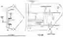
FIGS. 10A and 10B illustrates views of components of an invention disclosed herein. In particular, FIGS. 10A and 10B illustrates a bow 1000 having a grip 1010 with tensioner pivots and other components disclosed herein. In particular, bow 1000 has grip 1010, tensioner 1020, flex plate 1030, a tensioned element 1040, and stabilizer 1050.
Bow 1000 can have flex plates arranged above and below grip 1010. The thickness of such flex plates changes the stiffness of movement of the grip in relation to the rest of bow 1000 (e.g., with respect to where the flex plates are attached to the riser of bow 1000). The use of flex plates allows for different manufacturing and attachment options in comparison with other embodiments herein. In embodiments, the flex plates may be integrally manufactured with one or both of grip 1010 and the riser of bow 1000. The flex plates can be, if not integrally manufactured, rigidly coupled with the riser of bow 1000. Grip 1010 can be integrally formed with the flex plates, pinned thereto, or connected in other fashions.
Also shown in FIG. 10B in particular, stabilizer 1050 can be attached using an offset mount 1052. This offset mount 1052 can be used to connect a stabilizer to a grip arranged behind a riser without requiring a riser cutout as disclosed herein. Offset mount 1052 can be used (singularly or in combination with offset mounts and stabilizers on both sides of a riser) in any embodiment herein and bows other than bow 1000 without departing from the scope or spirit of the innovation.
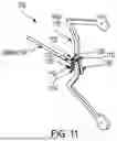
FIG. 11 illustrates views of components of an invention disclosed herein. In particular, FIG. 11 illustrates a bow 1100 having riser 1110, top pivot 1120, top bolt 1122, bottom pivot 1130, bottom bolt 1132, grip 1150, and stabilizer 1160. FIG. 11 describes an attachment of a grip 1150 disclosed herein without requiring modification of existing bows. Grip 1150 is arranged such that it wraps around or is isolated from riser 1110. In the illustrated embodiment, stabilizer 1160 is coupled to bow 1100 by way of pivot brace 1125, itself coupled to riser 1110 using a two pivot connection with top bolt 1122 and bottom bolt 1132.
Whether based on an open grip or wrapround shell, grip 1150 can be at least partially isolated from riser 1110 except by pivots via connections through grip extensions or other elements coupling grip 1150 to pivot brace 1125, and stabilizer 1160 can also be arranged along the same pivots to allow for the attenuation of transients during shooting.
Bow 1100 can have top riser extension 1112 and bottom riser extension 1114 for coupling riser 1110 to pivot brace 1125. Top riser extension 1112 and bottom riser extension 1114 can be rigid to riser. Top bolt 1122 and bottom bolt 1132 passing through each riser extension can couple pivot brace 1125 respectively to top riser extension 1112 and bottom riser extension 1114. In embodiments, grip 1150 can be “floated” such that it does not attach to riser 1110 directly but rather connects to one or more of top riser extension 1112, bottom riser extension 1114, and/or pivot brace 1125. In embodiments, one or more grip extensions can be part of grip 1150 or rigidly attached thereto and extend around and in front of riser 1110. Grip 1150 can in this regard pivot from top pivot 1120 and bottom pivot 1130. Such grip extensions can be coupled in front of or behind the pivot points of top pivot 1120 and bottom pivot 1130 to change the stiffness of each pivot based on the draw. Where the grip's attachment point is (or points are) arranged to connect “in front” of the pivots (e.g., on the other side of the pivot(s) from riser 1110 and elements rigidly coupled therewith), grip 1150 pivots with and using the same pivots as pivot brace 1125 and stabilizer 1160. The forces from drawing the bow can in such embodiments increase tension on top bolt 1122 and bottom bolt 1132 to facilitate effective pivoting and reduce transients during aiming and release. In alternative embodiments grip 1150 can be arranged to pivot independently from stabilizer 1160. In still other alternative embodiments, top bolt 1122 and bottom bolt 1132 can pass through riser 1110 to attach grip 1150 (either threaded through riser 1110 or floated therein with threads contacting riser extensions or other components that are not within the primary contour of riser 1110).
Components herein can be CNC machined. In embodiments, components (e.g., vibration dampening components) herein can be injection molded.
In embodiments, a contact point of frictionless pivots can be made out of hardened steel or other suitable materials to, e.g., reduce deformation of the materials due to the force of the bolt holding the surfaces together, or by the force of the grip pushing the surfaces together when the bow is drawn. Pivoting surfaces constructed of softer materials may result in contact points becoming inelastically deformed in a manner resulting in friction, which may degrade performance associated with a frictionless or near-frictionless pivot design.
In embodiments, washers or other components can be used on the riser and/or grip sides of the pivot to provide one or more points of contact where the bolt is rigidly connected to the riser projection or pivot bushing to resist translation on the x and/or y axes by the grip side of the pivots (e.g., resisting the grip translating in relation to other bow components). Such washers or other components could be made of hardened material such as steel or other materials such as rubber depending on the size, weight, draw length, draw weight, and other parameters of the bow, such that translation of the grip and riser relative to one another is resisted while the pivot point retains appropriate flex.
Alternately, in place of the two washers, one bushing could be used to span the pivot to reduce translation of the grip and riser relative to each other, and in specific embodiments the bushing may be a softer material such as rubber. The primary function of the pivots would be affected by the inclusion of these washers or bushings and would provide an additional neutral seeking force similar to that of the bolts. This design would permit additional adjustments and tuning in connection with the bolts.
In various embodiments, the pivot contact surfaces can be made of a different material (or different materials) than the riser, riser projections, grip, and/or pivot bushing. For example, the pivot contact surfaces may be made from hardened steel or other substantially hard material to provide a more efficient pivoting function, while the other portions of the bow (or any component disclosed herein) may be made of carbon fiber, aluminum or other material based on functions or material qualities (e.g., rigidity, strength-to-weight ratios).
In embodiments incorporating pivot bushings, such pivot bushings can be an integral part of the grip, or a separate piece combined to provide the grip with pivoting function.
In embodiments, springs can be included on the bolts to allow more gradual increases/decreases of the tension as the bolts are turned. In embodiments, the bolts can be arranged in a void to allow the bolts to flex a substantial portion of the length of the bolt rather than only at the pivot point.
The many features and advantages of the disclosure are apparent from the detailed specification, and it is intended to cover all such features and advantages of the disclosure, which fall within the true spirit, and scope of the disclosure. Since numerous modifications and variations will readily occur to those skilled in the art, it is not desired to limit the disclosure to the exact construction and operation illustrated and described, and, accordingly, all suitable modifications and equivalents that fall within the scope of the disclosure of this application are supported for claiming in this or related applications.
Claims
What is claimed is:1. An archery system, comprising:
a grip for a bow, wherein the grip is configured to be gripped by a user of a bow, and wherein the grip is configured not to directly contact a riser of the bow;
a top pivot operatively coupled to the grip and configured to pivotably connect the grip to a first grip attachment point of the riser; and
a bottom pivot operatively coupled to the grip and configured to pivotably connect the grip to a second grip attachment point of the riser.
2. The archery system of claim 1, comprising:
a stabilizer attachment point of the grip disposed between the top pivot and the bottom pivot.
3. The archery system of claim 2, comprising
a stabilizer coupled to the stabilizer attachment point.
4. The archery system of claim 3, comprising:
a stabilizer extension of the stabilizer;
a pivot end of the stabilizer; and
a stabilizer tension member of the stabilizer, wherein a stabilizer pivot is formed by the stabilizer extension, the pivot end, and the stabilizer tension member.
5. The archery system of claim 4, comprising a second pivot of the stabilizer.
6. The archery system of claim 2, comprising:
a riser cutout structure configured to jog around the stabilizer when the stabilizer is coupled to the stabilizer attachment point such that the riser does not interfere with the stabilizer.
7. The archery system of claim 1,
a stabilizer offset mount having an offset grip attachment point and a stabilizer attachment point, wherein the stabilizer offset mount is configured to couple the stabilizer to the grip to avoid interference with the riser.
8. The archery system of claim 1, comprising:
a top pivot assembly brace;
a bottom pivot assembly brace;
a top riser projection;
a bottom riser projection;
a top bolt through the top pivot assembly brace and top riser projection, wherein the top bolt is adjustable to increase and decrease tension on the top bolt to stiffen or loosen the top pivot; and
a bottom bolt through the bottom pivot assembly brace and bottom riser projection,
wherein the bottom bolt is adjustable to increase and decrease tension on the bottom bolt to stiffen or loosen the bottom pivot.
9. An archery system, comprising:
a stabilizer extension of a stabilizer;
a pivot end of the stabilizer; and
a stabilizer tension member of the stabilizer, wherein a stabilizer pivot is formed by the stabilizer extension, the pivot end, and the stabilizer tension member.
10. The archery system of claim 9, comprising:
a grip comprising an attachment point for the stabilizer.
11. The archery system of claim 10, comprising:
a riser; and
a riser cutout structure configured to jog around the stabilizer when the stabilizer is coupled to the stabilizer attachment point such that the riser does not interfere with the stabilizer.
12. The archery system of claim 10, comprising:
a stabilizer offset mount having an offset grip attachment point and the stabilizer attachment point, wherein the stabilizer offset mount is configured to couple the stabilizer to the grip to avoid interference with a riser.
13. The archery system of claim 10, wherein the grip is configured not to directly contact a riser of a bow.
14. The archery system of claim 13, comprising:
a top pivot operatively coupled to the grip and configured to pivotably connect the grip to a first grip attachment point of the riser; and
a bottom pivot operatively coupled to the grip and configured to pivotably connect the grip to a second grip attachment point of the riser.
15. The archery system of claim 14, comprising:
a top pivot assembly brace;
a bottom pivot assembly brace;
a top riser projection;
a bottom riser projection;
a top bolt through the top pivot assembly brace and top riser projection, wherein the top bolt is adjustable to increase and decrease tension on the top bolt to stiffen or loosen the top pivot; and
a bottom bolt through the bottom pivot assembly brace and bottom riser projection,
wherein the bottom bolt is adjustable to increase and decrease tension on the bottom bolt to stiffen or loosen the bottom pivot.
16. The archery system of claim 9, comprising a second pivot of the stabilizer.
17. A method, comprising:
providing a grip for a bow;
coupling the grip to a riser of the bow using a first pivot; and
coupling the grip to the riser of the bow using a second pivot.
18. The method of claim 17, comprising:
providing a stabilizer for the bow; and
coupling the stabilizer to the grip.
19. The method of claim 18, comprising:
a riser cutout of the riser configured to jog around the stabilizer when the stabilizer is coupled to a stabilizer attachment point such that the riser does not interfere with the stabilizer.
20. The method of claim 18, comprising:
a stabilizer offset mount having an offset grip attachment point and a stabilizer attachment point, wherein the stabilizer offset mount is configured to couple the stabilizer to the grip to avoid interference with the riser.
Images & Drawings included:

Sources:
- United States Patent and Trademark Office - verify current appl. status at the USPTO↗
Recent applications in this class:
- » 20260085906 2026-03-26
COMPOUND BOW ATTACHMENT APPARATUS TO REDUCE TORQUE AND INCREASE STABILITY - » 20260029210 2026-01-29
Archery Bow Riser Weight - » 20260016260 2026-01-15
ARCHERY BOW MONITORING - » 20260002755 2026-01-01
Archery Bow Limb Construction - » 20250305789 2025-10-02
Stabilization Assembly - » 20240426568 2024-12-26
MATERIALS FOR USE IN ARCHERY EQUIPMENT - » 20240418473 2024-12-19
Bow Support Systems and Related Devices and Methods - » 20240369318 2024-11-07
BOW STABILIZER AND WEIGHT SYSTEM - » 20240302126 2024-09-12
ARCHERY STABILIZER MOUNT AND RELATED METHOD OF USE - » 20240159490 2024-05-16
Archery Bow Stabilizer