HANDGUARD ATTACHMENT ASSEMBLY
US20260177352A1
2026-06-25
19/429,406
2025-12-22
Smart Summary: A handguard attachment assembly helps secure a handguard to the barrel of a firearm. It consists of two main parts, called the first body and the second body. Each part has projections on opposite sides that help connect them. There are adjustable fasteners that link these projections together for a secure fit. This design ensures that the handguard stays firmly attached during use. 🚀 TL;DR
Abstract:
A handguard attachment assembly for securing a handguard to a barrel assembly of a firearm. The assembly has a first body and a second body. Each of the first and second bodies includes a first side and a second side oppositely disposed. A first projection extends from the first side. A second projection extends from the second side. A first adjustable fastener is configured to couple the first projection of the first body and the second projection of the second body. A second adjustable fastener is configured to couple said second projection of said first body and said first projection of said second body.
Applicant:
Interested in similar patents?
Get notified when new applications in this technology area are published.
Classification:
F41C23/16 » CPC main
Butts; Butt plates; Stocks Forestocks; Handgrips; Hand guards
F41A3/66 » CPC further
Breech mechanisms, e.g. locks; Mounting of breech-blocks; Accessories for breech-blocks or breech-block mountings Breech housings or frames; Receivers
F41C23/02 » CPC further
Butts; Butt plates; Stocks Attachment of slings
Description
CROSS REFERENCE TO RELATED APPLICATIONS
This Application is based upon and claims priority to U.S. provisional patent application No. 63/737,879, filed on Dec. 23, 2024, and entitled “Handguard Attachment Assembly,” which application is incorporated by reference herein in its entirety.
FIELD
This disclosure relates to an assembly for securing a handguard to a barrel assembly of a firearm.
BACKGROUND
Handguards can be an important element of a firearm. Handguards may provide a mechanism to mount accessories, such as lights, lasers, and optics, to the firearm. Handguards may also protect the barrel and protect the shooter's hand from the barrel's heat and other irritants while providing a secure grip for the shooter that may help the shooter maintain a steady firing position. Free-float handguards, which do not touch the barrel, may increase accuracy by reducing barrel harmonics. Further, free-float handguards may be more rigid and stronger than non-free-float options, but can be more difficult to install. Free-float handguards are typically coupled to the barrel nut of the barrel assembly of the firearm. Thus, precise alignment of the barrel nut and the handguard are critical to ensure the handguard sits straight on the barrel and is properly secured to prevent possible damage to the firearm and to improve firing accuracy. Further, some designs require numerous components and/or fasteners to properly secure the handguard to the barrel assembly. For example, a conventional design may include 16 screws and 16 nuts to secure the handguard to the barrel, making installation tedious and cumbersome.
SUMMARY
An example handguard attachment assembly for securing a firearm handguard having a longitudinal axis to a barrel assembly arranged coaxially is disclosed.
An example assembly according to the disclosure is comprised of a first body and a second body. Each of the first and second bodies comprises a first side and a second side oppositely disposed. A first projection extends from the first side. A second projection extends from the second side. A first adjustable fastener is configured to couple the first projection of the first body and the second projection of the second body. A second adjustable fastener is configured to couple the second projection of the first body and the first projection of the second body.
In an example embodiment, at least one of the first body or the second body comprises an opening configured to receive a sling attachment. In a further example embodiment, the opening is a socket. In a further example embodiment, the opening is a flush cap and the sling attachment is a quick detach sling swivel.
In an example embodiment, each of the first projections and the second projections comprises a respective aperture configured to receive one of the first and second adjustable fasteners. In a further example embodiment, the aperture of the first projection of the first body comprises threads configured to engage a threaded end of the first adjustable fastener, and the aperture of the first projection of the second body comprises threads configured to engage a threaded end of the second adjustable fastener. In an example embodiment, the second projection of the first body comprises a recessed surface surrounding the aperture of the second projection of the first body. The recessed surface of the second projection of the first body is configured to engage a head of the second adjustable fastener. The second projection of the second body comprises a recessed surface surrounding the aperture of the second projection of the second body. The recessed surface of the second projection of the second body is configured to engage a head of the first adjustable fastener. In an example embodiment, the first projections of the first and second bodies comprise respective protrusions. The apertures of the first projections of the first and second bodies extend through the respective protrusions.
In an example embodiment, the first adjustable fastener is a first screw and the second adjustable fastener is a second screw.
In an example embodiment, in a coupled position, the first projection of the first body and the second projection of the second body are coupled and the second projection of the first body and the first projection of the second body are coupled. In the coupled position, the first adjustable fastener and the second adjustable fastener are configured to draw the first body and the second body together to an assembled configuration. In the assembled configuration, the handguard is secured to the barrel assembly via the assembly.
In a further example embodiment, each of the first and second bodies further comprises an inner surface. In the assembled configuration, the inner surface of the first body faces the second body and the inner surface of the second body faces the first body.
In a further example embodiment, each of the inner surfaces of the first and second bodies comprises a first portion. In the assembled configuration, the first portion is adapted to at least partially surround a barrel nut of the barrel assembly.
In a further example embodiment, the first projection comprises a first section of the first portion of the inner surface, the second projection comprises a second section of the first portion of the inner surface, and the body extending between the first and second sides comprises a third section of the first portion of the inner surface.
In a further example embodiment, each of the first body and the second body has a first axis. In the assembled configuration, the first axis of the first body and the first axis of the second body extend parallel or substantially parallel (e.g., within 10 degrees of parallel) to the longitudinal axis.
In a further example embodiment, in the assembled configuration, the assembly comprises a first plane containing the first axis of the first body and the first axis of the second body.
In a further example embodiment, the third section of the inner surface is perpendicular or substantially perpendicular (e.g., within 10 degrees of perpendicular) to the first plane.
In a further example embodiment, the first section of the inner surface extends from the first side at a first angle between 0 and 90° with respect to the first plane, and the second section of the inner surface extends from the second side at a second angle between 0 and 90° with respect to the first plane. Optionally, the first angle and the second angle are about 30° with respect to the first plane.
In an example embodiment, the inner surface comprises a second portion adapted to engage a portion of the barrel assembly.
In an example embodiment, each of the first projection and the second projection comprises an end surface. In the assembled configuration, the end surface is configured to engage the handguard.
In an example embodiment, the first body is integrally formed as a monolithic structure and the second body is integrally formed as a monolithic structure.
The disclosure also encompasses a firearm. In an example embodiment, the firearm comprises a firearm handguard having a longitudinal axis. The firearm handguard comprises a frame defining a first slot and a second slot oppositely disposed. A barrel assembly is arranged coaxially with the firearm handguard. The barrel assembly comprises a barrel. The firearm handguard surrounds the barrel. A handguard attachment assembly couples the firearm handguard to the barrel assembly. In an assembled configuration of the handguard attachment assembly, the firearm handguard is secured to the barrel assembly. The handguard attachment assembly comprises a first body and a second body. Each of the first and second bodies comprises a first side and a second side oppositely disposed. A first projection extends from the first side. A second projection extends from the second side. A first adjustable fastener couples the first projection of the first body and the second projection of the second body. A second adjustable fastener couples the second projection of the first body and the first projection of the second body. The first slot is configured to receive the first body of the assembly and the second slot is configured to receive the second body of the assembly.
In an example embodiment, at least one of the first body or the second body comprises an opening configured to receive a sling attachment. In a further example embodiment, the opening is a socket. In a further example embodiment, the opening is a flush cap and the sling attachment is a quick detach sling swivel.
In an example embodiment, each of the first projections and the second projections comprises a respective aperture. The aperture receives one of the first and second adjustable fasteners. In a further example embodiment, the aperture of the first projection of the first body comprises threads that engage a threaded end of the first adjustable fastener, and the aperture of the first projection of the second body comprises threads that engage a threaded end of the second adjustable fastener. In an example embodiment, the second projection of the first body comprises a recessed surface surrounding the aperture of the second projection of the first body that engages a head of the first adjustable fastener. The second projection of the second body comprises a recessed surface surrounding the aperture of the second projection of the second body that engages a head of the second adjustable fastener. In an example embodiment, the first projections of the first and second bodies comprise respective protrusions. The apertures of the first projections of the first and second bodies extend through the protrusion. The handguard comprises a first opening and a second opening. The first opening receives the protrusion of the first projection of the first body and the second opening receives the protrusion of the first projection of the second body.
In an example embodiment, the first adjustable fastener is a first screw and the second adjustable fastener is a second screw.
In an example embodiment, the handguard comprises a first opening and a second opening. The first adjustable fastener extends through the first opening and the second adjustable fastener extends through the second opening.
In a further example embodiment, each of the first and second bodies further comprises an inner surface. The inner surface of the first body faces the second body and the inner surface of the second body faces the first body.
In a further example embodiment, each of the inner surfaces of the first and second bodies comprises a first portion. In the assembled configuration, the first portion is adapted to at least partially surround a barrel nut of the barrel assembly.
In a further example embodiment, the first projection comprises a first section of the first portion of the inner surface, the second projection comprises a second section of the first portion of the inner surface, and the body extending between the first and second sides comprises a third section of the first portion of the inner surface.
In a further example embodiment, each of the first body and the second body has a first axis, wherein in the assembled configuration, the first axis of the first body and the first axis of the second body extend parallel or substantially parallel (e.g., within 10 degrees of parallel) to the longitudinal axis.
In a further example embodiment, in the assembled configuration, the assembly comprises a first plane containing the first axis of the first body and the first axis of the second body.
In a further example embodiment, the third section of the inner surface is perpendicular or substantially perpendicular (e.g., within 10 degrees of perpendicular) to the first plane.
In a further example embodiment, the first section of the inner surface extends from the first side at a first angle between 0 and 90° with respect to the first plane, and the second section of the inner surface extends from the second side at a second angle between 0 and 90° with respect to the first plane. Optionally, the first angle and the second angle are about 30° with respect to the first plane.
In an example embodiment, the inner surface comprises a second portion adapted to engage a portion of the barrel assembly.
In an example embodiment, each of the first projection and the second projection comprises an end surface engaging the handguard.
In an example embodiment, the frame of the handguard comprises a first slot surface defining the first slot. The first slot surface is complementary to a first boundary surface of the first body. The frame of the handguard comprises a second slot surface defining the second slot. The second slot surface is complementary to a second boundary surface of the second body.
In an example embodiment, the first body is integrally formed as a monolithic structure and the second body is integrally formed as a monolithic structure.
The disclosure also encompasses a method of assembling the firearm. The method comprises:
-
- positioning the handguard around the barrel assembly;
- inserting the first body of the handguard attachment assembly in the first slot;
- inserting the second body of the handguard attachment assembly in the second slot;
- connecting the first projection of the first body to the second projection of the second body by inserting a first adjustable fastener through the handguard;
- connecting the second projection of the first body to the first projection of the second body by inserting a second adjustable fastener through the handguard; and
- adjustably tightening the first and second adjustable fasteners to draw the first and the second bodies toward one another to secure the handguard to the barrel assembly.
BRIEF DESCRIPTION OF THE DRAWINGS
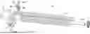
FIG. 1 shows a perspective view of an example firearm according to the disclosure;
FIG. 2 shows a right side elevation view of the example firearm shown in FIG. 1;
FIG. 3 shows a left side elevation view of the example firearm shown in FIG. 2;
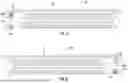
FIG. 4 shows an example handguard and barrel assembly with an example handguard attachment assembly in a preassembled configuration;
FIG. 5 shows a right side elevation view of an example handguard according to the disclosure;
FIG. 6 shows a left side elevation view of the example handguard of FIG. 5;
FIG. 7 shows a right side elevation view of an example barrel
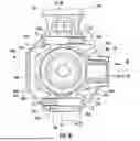
assembly according to the disclosure; FIG. 8 shows a section view of the example firearm shown in FIG. 1, taken along the plane indicated by line 8-8 in FIG. 2;
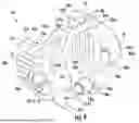
FIG. 9 shows a perspective view of an example handguard attachment assembly in an assembled configuration according to the disclosure;
FIG. 10 shows a rear elevation view of the handguard attachment assembly shown in FIG. 9;
FIG. 11 shows a perspective view of an example barrel assembly and an example handguard attachment assembly in an assembled configuration as disclosed herein; and
FIG. 12 shows an example sling attachment according to the disclosure.
DETAILED DESCRIPTION
The present disclosure can be understood more readily by reference to the accompanying detailed description, which includes examples, claims and drawings, in which some, but not all embodiments of the invention are shown. Indeed, this invention may be embodied in many different forms and should not be construed as limited to the embodiments set forth herein; rather, these embodiments are provided so that this disclosure will satisfy applicable legal requirements. Like numbers refer to like elements throughout. It is to be understood that this invention is not limited to the particular methodology and protocols described, as such may vary. It is also to be understood that the terminology used herein is for the purpose of describing particular embodiments only, and is not intended to limit the scope of the present invention.
Many modifications and other embodiments of the invention set forth herein will come to mind to one skilled in the art to which the invention pertains having the benefit of the teachings presented in the foregoing description and the associated drawings. Therefore, it is to be understood that the invention is not to be limited to the specific embodiments disclosed and that modifications and other embodiments are intended to be included within the scope of the appended claims. Although specific terms are employed herein, they are used in a generic and descriptive sense only and not for purposes of limitation.
As used herein the singular forms “a,” “an,” and “the” can optionally include plural referents unless the context clearly dictates otherwise. For example, use of the term “an opening” can represent disclosure of embodiments in which only a single opening is provided, and unless the context dictates otherwise, can also represent disclosure of embodiments in which a plurality of such openings are provided.
All technical and scientific terms used herein have the same meaning as commonly understood to one of ordinary skill in the art to which this invention belongs unless clearly indicated otherwise.
As used herein, the terms “optional” or “optionally” mean that the subsequently described event or circumstance may or may not occur, and that the description includes instances where said event or circumstance occurs and instances where it does not.
As used herein, the term “at least one of” is intended to be synonymous with “one or more of.” For example, “at least one of A, B and C” explicitly includes only A, only B, only C, and combinations of each.
Ranges can be expressed herein as from “about” one particular value, and/or to “about” another particular value. When such a range is expressed, another aspect includes from the one particular value and/or to the other particular value. Similarly, when values are expressed as approximations, by use of the antecedent “about,” it will be understood that the particular value forms an-other aspect. It will be further understood that the endpoints of each of the ranges are significant both in relation to the other endpoint, and independently of the other endpoint. Optionally, in some aspects, when values are approximated by use of the antecedent “about,” it is contemplated that values within up to 15%, up to 10%, up to 5%, or up to 1% (above or below) of the particularly stated value can be included within the scope of those aspects. Similarly, use of “substantially” (e.g., “substantially parallel”) or “generally” (e.g., “generally planar”) should be under-stood to include embodiments in which angles are within ten degrees, or within five degrees, or within one degree.
The word “or” as used herein means any one member of a particular list and, in alternative embodiments, unless context dictates otherwise, can include any combination of members of that list.
The terms “forward,” “rearward,” “top,” “bottom,” and derivatives thereof are meant to indicate position with respect to the firearm when held in a firing or use position by a shooter.
It is to be understood that unless otherwise expressly stated, it is in no way intended that any method set forth herein be construed as requiring that its steps be performed in a specific order. Accordingly, where a method claim does not actually recite an order to be followed by its steps or it is not otherwise specifically stated in the claims or descriptions that the steps are to be limited to a specific order, it is in no way intended that an order be inferred, in any respect. This holds for any possible non-express basis for interpretation, including: matters of logic with respect to arrangement of steps or operational flow; plain meaning derived from grammatical organization or punctuation; and the number or type of aspects described in the specification.
The following description supplies specific details in order to provide a thorough understanding. Nevertheless, the skilled artisan would understand that the device, systems, and associated methods can be implemented and used without employing these specific details. Indeed, the device, systems, and associated methods can be placed into practice by modifying the illustrated device, systems, and associated methods and may be used in conjunction with any other apparatus and techniques conventionally used in the industry.
As further explained herein, it is contemplated that the disclosed firearms, firearm components, and related systems and methods can improve upon existing devices for securing a handguard to a barrel assembly of a firearm. More specifically, it is contemplated that the disclosed firearms, firearm components, and related systems and methods can ensure proper alignment of the handguard and the barrel and/or limit the number of components, including fasteners, to make installation easier and more efficient.
FIGS. 1-3 show a firearm 10, in this example a semi-automatic rifle. Although depicted in the drawings as a semi-automatic rifle, it is contemplated that other firearm designs and configurations can be compatible with the current disclosure. The firearm 10 comprises a firearm handguard 20 having a longitudinal axis 22. As shown in FIGS. 4-6, the firearm handguard 20 comprises a frame 24 defining a first slot 26 and a second slot 28 oppositely disposed. As shown in FIG. 5, the frame 24 of the handguard 20 may comprise a first slot surface 108 which defines the first slot 26. As shown in FIG. 6, the frame 24 of the handguard 20 may comprise a second slot surface 112 which defines the second slot 28.
As shown in FIG. 1-3, a barrel assembly 30 is arranged coaxially with the firearm handguard 20. As shown in FIG. 7, the barrel assembly 30 comprises a barrel 32 and components for attaching the barrel 32 to the receiver assembly. The barrel assembly 30 may further comprise a barrel nut 34. Although depicted in the drawings as a hex nut, it is contemplated that any barrel nut 34 configuration may be compatible with the current disclosure. Optionally, the barrel assembly 30 may further comprise a barrel hinge 36. The barrel hinge 36 may allow the firearm 10 to fold about the barrel hinge 36 to a folded position. An example foldable firearm and barrel hinge are disclosed in U.S. Publication No. 2024/0240892 which is incorporated herein by reference. Although not shown, the barrel assembly 30 may comprise at least a portion of an upper receiver of the firearm 10 proximate to the barrel nut 34. As shown in FIG. 4, the firearm handguard 20 surrounds the barrel assembly 30 such that the first slot 26 and the second slot 28 may be aligned with the barrel nut 34 along the longitudinal axis 22.
As shown in FIGS. 1-3, a handguard attachment assembly 40 couples the firearm handguard 20 to the barrel assembly 30. In an assembled configuration of the handguard attachment assembly 40, the firearm handguard 20 is secured to the barrel assembly 30 by the handguard attachment assembly 40.
As shown in FIGS. 8-11, the handguard attachment assembly 40 comprises a first body 42 and a second body 44. Optionally, the first body 42 is integrally formed as a monolithic structure, and the second body 44 is integrally formed as a monolithic structure. Optionally, at least one of the first body 42 or the second body 44 comprises an opening 60 configured to receive a sling attachment 64 as is known in the art. The opening may be or comprise a socket 61. The opening may be or comprise a flush cap 62 as shown in the figures and the sling attachment 64 may be a quick detach (QD) sling swivel 66 such as the example QD sling swivel 66 shown in FIG. 12. As shown in FIGS. 9-11, each of the first body 42 and the second body 44 has a first axis 88a, 88b, respectively. As shown in FIG. 11, in the assembled configuration of the assembly 40, the first axis 88a of the first body 42 and the first axis 88b of the second body 44 may extend parallel or substantially parallel (for example, within 10° of parallel) to the longitudinal axis 22. As shown in FIGS. 8 and 10, in the assembled configuration of the assembly 40, a first plane 98 may contain the first axis 88a of the first body 42 and the first axis 88b of the second body 44.
As shown in FIGS. 1-4, the first slot 26 of the handguard 20 is configured to receive the first body 42 of the assembly 40. As shown in FIG. 9, the first body 42 has a first boundary surface 110. With reference to FIGS. 5 and 9, the first boundary surface 110 of the first body 42 may be complementary to the first slot surface 108. For example, the geometry of the first boundary surface 110 may be complementary to the geometry of the first slot surface 108 such that the first boundary surface 110 engages or at least partially engages the first slot surface 108 when the first body 42 is inserted into and received by the first slot 26. As shown in FIG. 3, the second slot 28 of the handguard 20 is configured to receive the second body 44 of the assembly 40. As shown in FIG. 9, the second body 44 has a second boundary surface 114. With reference to FIGS. 6 and 9, the second boundary surface 114 of the second body 44 may be complementary to the second slot surface 112. For example, the geometry of the second boundary surface 114 may be complementary to the geometry of the second slot surface 112 such that the second boundary surface 114 engages or at least partially engages the second slot surface 112 when the second body 44 is inserted into and received by the second slot 28.
As shown in FIGS. 8-11, each of the first and second bodies 42, 44 includes a respective first side portion 46a, 46b and a respective second side portion 48a, 48b oppositely disposed along an axis 89 extending transversely (optionally perpendicularly or substantially perpendicularly, for example within 5°to 10° of perpendicular) to the first axes 88a, 88b. A first projection 50a extends from the first side portion 46a of the first body 42 along an axis perpendicular to plane 98 in a first direction. A second projection 50b extends from the first side portion 48a of the first body 42 along an axis perpendicular to plane 98 in a second direction, opposite the first direction. A first projection 50b extends from the first side portion 46b of the second body 44 along an axis perpendicular to plane 98 in the second direction. A second projection 52b extends from the second side portion 48b of the second body 44 along an axis perpendicular to plane 98 in the first direction. As shown in FIGS. 8-10, each of the first projections 50a, 50b and the second projections 52a, 52b of the first and second bodies 42, 44 may comprise respective end surfaces 106a, 106b that engage the handguard 20 when the first body 42 is inserted into and received by the first slot 26 and the second body 44 is inserted into and received by the second slot 28.
A first adjustable fastener 54 couples the first projection 50a of the first body 42 and the second projection 52b of the second body 44. A second adjustable fastener 56 couples the second projection 52a of the first body 42 and the first projection 50b of the second body 44. Optionally, the first adjustable fastener 54 may be a first screw 80. Optionally, the second adjustable fastener 56 may be a second screw 82. As shown in FIG. 8, each of the first projections 50a, 50b may comprise respective apertures 55a, 55b, and the second projections 52a, 52b may comprise respective apertures 58a, 58b to receive one of the first and second adjustable fasteners 54, 56. The aperture 55a of the first projection 50a of the first body 42 may comprise threads 57 that engage a threaded end 51 of the first adjustable fastener 54. The aperture 55b of the first projection 50b of the second body 44 may comprise threads 59 that engage a threaded end 53 of the second adjustable fastener 56. The second projection 52a of the first body 42 may comprise a recessed surface 70 surrounding the aperture 58a of the second projection 52a of the first body 42 that engages a head 72 of the second adjustable fastener 56. The second projection 52b of the second body 44 may comprise a recessed surface 74 surrounding the aperture 58b of the second projection 52b of the second body 44 that engages a head 76 of the first adjustable fastener 54. The first projection 50a of the first body 42 and the first projection 50b of the second body 44 may further comprise respective protrusions 78a, 78b. Each of the apertures 55a, 55b of the first projections 50a, 50b, of the first and second bodies 42, 44 may extend through the respective protrusions 78a, 78b. Advantageously, the protrusions 78a, 78b may provide additional threaded length of the apertures 55a, 55b of the first projections 50a of the first body and 50b of the second body thereby increasing the engagement length of the threaded ends 51, 53 of the first and second adjustable fasteners 54, 56 and the respective threads 57, 59 of the apertures 55a, 55b.
As shown in FIG. 8, the handguard 20 may comprise a first opening 23 and a second opening 25. The first adjustable fastener 54 may extend through the first opening 23 and the second adjustable fastener 56 may extend through the second opening 25. The first opening 23 may receive the protrusion 78 of the first projection 50a of the first body 42. The second opening 25 may receive the protrusion 78 of the first projection 50b of the second body 44.
As shown in FIGS. 9-11, the first and second bodies 42, 44 may further comprise inner surfaces 84a and 84b, respectively. The inner surfaces 84a, 84b may be configured to engage at least a portion of the barrel assembly 30. The inner surfaces 84a, 84b may extend through the respective first and second slots 26, 28 to engage the barrel assembly 30 as shown in FIG. 11. The inner surface 84a of the first body 42 may face the second body 44. The inner surface 84b of the second body 44 may face the first body 42.
As shown in FIGS. 9 and 11, each of the inner surfaces 84a, 84b of the first and second bodies 42, 44 may comprise a respective first portion 86a, 86b. In the assembled configuration, the first portions 86a, 86b may be adapted to at least partially surround the barrel nut 34, with clearance, so that there is no interaction between the first and second bodies 42, 44 and the barrel nut 34 of the barrel assembly 30. Alternatively, at least some part of the first portions 86a, 86b may be adapted to engage the barrel nut 34 of the barrel assembly 30. Engagement between at least some part of the first portions 86a, 86b and the barrel nut 34 may retain the barrel nut 34 in proper alignment or position and prevent the barrel nut 34 from loosening during use. The first projections 50a, 50b may comprise respective first sections 90a, 90b of the first portions 86a, 86b of the inner surfaces 84a, 84b. The second projections 52a, 52b may comprise respective second sections 92a, 92b of the first portions 86a, 86b of the inner surfaces 84a, 84b. As shown in FIG. 10, the first sections 90a, 90b of the inner surfaces 84a, 84b may extend from the first side portions 46a, 46b at respective first angles 102a, 102b between 0 and 90° with respect to the first plane 98, and the second sections 92a, 92b of the inner surfaces 84a, 84b may extend from the second side portions 48a, 48b at respective second angles 104a, 104b between 0 and 90° with respect to the first plane 98. Optionally, the first angles 102a, 102b and the second angles 104a, 104b may each be about 30° (for example, within 5° of 30° (from 25 to 35 degrees)) or 30° with respect to the first plane 98 to clear or avoid respective portions of the exterior surface of the barrel nut 34, which in this example, is a hex nut (as shown in FIG. 8). The bodies 42, 44 extending between the first and second side portions 46a, 46b, 48a, 48b may comprise respective third sections 96a, 96b, of the first portions 86a, 86b of the inner surfaces 84a, 84b. As shown in FIGS. 8 and 10, the third sections 96a, 96b of the inner surfaces 84a, 84b may be perpendicular or substantially perpendicular (for example, within 10° of perpendicular) to the first plane 98. The configuration of the first portions 86a, 86b of the inner surfaces 84a, 84b, including, for example, the lengths and orientations of the first, second, and third sections 90a, 90b, 92a, 92b, 96a, 96b, may be complementary to the exterior geometry of the barrel nut 34 to allow the first portions 86a, 86b of the inner surfaces 84a, 84b so as to not interact with the exterior surface of the barrel nut 34. For example, the configuration of the first portions 86a, 86b of the inner surfaces 84a, 84b may be complementary to a barrel nut 34 that is a hex nut as shown in the figures. The corresponding geometry of the first portions 86a, 86b of the inner surfaces 84a, 84b and the barrel nut 34 which may provide clearance between the first and second bodies 42, 44 and the barrel nut 34 allows the handguard attachment assembly 40 to attach the handguard 20 to the barrel assembly 30 without depending on or requiring a barrel nut 34. The corresponding geometry of the first portions 86a, 86b of the inner surfaces 84a, 84b and the barrel nut 34 may retain the barrel nut 34 in proper alignment or a proper position and/or prevent the barrel nut 34 from loosening.
As shown in FIGS. 9 and 11, the inner surfaces 84a, 84b may comprise respective second portions 87a, 87b adapted to engage a portion (e.g., the barrel hinge 36) of the barrel assembly 30. Although depicted as engaging the barrel hinge 36 in the drawings, it is contemplated that the second portions 87a, 87b of the inner surfaces 84a, 84b are adapted to engage an upper receiver of the receiver assembly and/or the barrel itself. The second portions 87a, 87b may comprise recesses 118a, 118b, respectively, configured to receive protrusions 120a, 120b projecting from the exterior surface the barrel assembly 30 (e.g., a protrusion 120a projecting from the exterior surface of the barrel hinge 36). Engagement between the second portions 87a, 87b of the inner surfaces 84a, 84b and the portion of the barrel assembly 30 (e.g., the barrel hinge 36) may ensure proper alignment of the assembly 40 with respect to the portion of the barrel assembly 30 (e.g., the barrel hinge 36) thereby ensuring proper alignment of the handguard 20 with respect to the portion of the barrel assembly 30 (e.g., barrel hinge 36), and thus, ultimately ensuring proper alignment of the handguard and the barrel 32.
To assemble the handguard attachment assembly 40 to secure the handguard 20 to the barrel assembly 30 of a firearm 10, the first body 42 of the assembly 40 may be inserted into and received by the first slot 26 of the frame 24 of the handguard 20. The second body 44 of the assembly 40 may be inserted into and received by the second slot 28 of the frame 24 of the handguard 20. The first adjustable fastener 54 may be inserted through the aperture 58b in the second projection 52b of the second body 44, through the first opening 23 in the handguard 20 frame 24, and through the aperture 55a in the first projection 50a of the first body 42. The second adjustable fastener 56 may be inserted through the aperture 58a in the second projection 52a of the first body 42, through the second opening 25 in the handguard 20 frame 24, and through the aperture 55b in the first projection 50b of the second body 44. The adjustable fasteners 54, 56 may be tightened so that end surfaces 106a, 106b of the projections 50a, 52a, 50b, 52b of the first and second bodies 42, 44 engage the frame 24 of the handguard 20. The adjustable fasteners 54, 56 may be tightened so that at least a portion of the inner surfaces 84a, 84b of the first and second body 42, 44 of the assembly 40 engage the barrel assembly 30. Specifically, upon tightening of the adjustable fasteners 54, 56 to the assembled condition, the second portions 87a, 87b of the inner surfaces 84a, 84b may engage the barrel hinge 36 of the barrel assembly 30.
It is expected that the example handguard attachment assembly 40 and corresponding methods according to the disclosure will allow a user to secure a handguard 20 to a barrel assembly 30 of a firearm 10. Further, it is expected that the example handguard attachment assembly 40 ensures proper alignment of the handguard 20 and the barrel assembly 30.
All of the embodiments of the claimed invention described herein are provided expressly by way of example only. Innumerable variations and modifications may be made to the example embodiments described herein without departing from the concept of this disclosure. Additionally, the scope of this disclosure is intended to encompass any and all modifications and combinations of all elements, features, and aspects described in the specification and claims, and shown in the drawings. Any and all such modifications and combinations are intended to be within the scope of this disclosure.
Exemplary Aspects
In view of the described devices, systems, and methods and variations thereof, herein below are described certain more particularly described aspects of the invention. These particularly recited aspects should not however be interpreted to have any limiting effect on any different claims containing different or more general teachings described herein, or that the “particular” aspects are somehow limited in some way other than the inherent meanings of the language literally used therein.
-
- Aspect 1: An assembly for securing a firearm handguard having a longitudinal axis to a barrel assembly arranged coaxially, said assembly comprising:
- a first body;
- a second body; each of said first and second bodies comprising:
- a first side and a second side oppositely disposed,
- a first projection extending from said first side, and
- a second projection extending from said second side;
- a first adjustable fastener configured to couple said first projection of said first body and said second projection of said second body; and
- a second adjustable fastener configured to couple said second projection of said first body and said first projection of said second body.
- Aspect 2: The assembly according to aspect 1, wherein at least one of said first body or said second body comprises an opening configured to receive a sling attachment.
- Aspect 3: The assembly according to aspect 2, wherein said opening is a socket.
- Aspect 4: The assembly according to aspect 2 or aspect 3, wherein said opening is a flush cap and said sling attachment is a quick detach sling swivel.
- Aspect 5: The assembly according any of aspects 1-4, wherein each of said first projections and said second projections comprises a respective aperture configured to receive one of said first and second adjustable fasteners.
- Aspect 6: The assembly according to aspect 5, wherein said aperture of said first projection of said first body comprises threads configured to engage a threaded end of said first adjustable fastener, and said aperture of said first projection of said second body comprises threads configured to engage a threaded end of said second adjustable fastener.
- Aspect 7: The assembly according to aspect 5 or aspect 6, wherein said second projection of said first body comprises a recessed surface surrounding said aperture of said second projection of said first body, said recessed surface of said second projection of said first body being configured to engage a head of said second adjustable fastener, and said second projection of said second body comprises a recessed surface surrounding said aperture of said second projection of said second body, said recessed surface of said second projection of said second body being configured to engage a head of said first adjustable fastener.
- Aspect 8: The assembly according to any of aspects 5-7, wherein said first projections of said first and second bodies comprise respective protrusions, and wherein said apertures of said first projections of said first and second bodies extend through said protrusion.
- Aspect 9: The assembly according to any of aspects 1-8, wherein said first adjustable fastener is a first screw and said second adjustable fastener is a second screw.
- Aspect 10: The assembly according to any of aspects 1-9, wherein in a coupled position, the first projection of the first body and the second projection of the second body are coupled and the second projection of the first body and the first projection of the second body are coupled, wherein in said coupled position, said first adjustable fastener and said second adjustable fastener are configured to draw said first body and said second body together to an assembled configuration, wherein in said assembled configuration, said handguard is secured to said barrel assembly via said assembly.
- Aspect 11: The assembly according to any of aspects 1-10, wherein each of said first and second bodies further comprises an inner surface, wherein in said assembled configuration, said inner surface of said first body faces said second body and said inner surface of said second body faces said first body.
- Aspect 12: The assembly according to aspect 11, wherein each of said inner surfaces of said first and second bodies comprises a first portion, wherein in said assembled configuration, said first portion is adapted to at least partially surround a barrel nut of said barrel assembly.
- Aspect 13: The assembly according to aspect 12, wherein said first projection comprises a first section of said first portion of said inner surface, said second projection comprises a second section of said first portion of said inner surface, and said body extending between said first and second sides comprises a third section of said first portion of said inner surface.
- Aspect 14: The assembly according to any one of aspects 10-13, wherein each of said first body and said second body has a first axis, wherein in said assembled configuration, said first axis of said first body and said first axis of said second body extend parallel or substantially parallel to said longitudinal axis.
- Aspect 15: The assembly according to aspect 13, wherein each of said first body and said second body has a first axis, wherein in said assembled configuration, said first axis of said first body and said first axis of said second body extend parallel or substantially parallel to said longitudinal axis, and wherein in said assembled configuration, said assembly comprises a first plane containing said first axis of said first body and said first axis of said second body.
- Aspect 16: The assembly according to aspect 15 wherein said third section of said inner surface is substantially perpendicular to said first plane.
- Aspect 17: The assembly according to aspect 15 or aspect 16, wherein said first section of said inner surface extends from said first side at a first angle between 0 and 90° with respect to said first plane, and said second section of said inner surface extends from said second side at a second angle between 0 and 90° with respect to said first plane.
- Aspect 18: The assembly according to aspect 17, wherein said first angle and said second angle are about 30° with respect to said first plane.
- Aspect 19: The assembly according to any of aspects 11-18, wherein said inner surface comprises a second portion adapted to engage a portion of the barrel assembly.
- Aspect 20: The assembly according to any of aspects 10-19, wherein each of said first projection and said second projection comprises an end surface, wherein in said assembled configuration, said end surface is configured to engage said handguard.
- Aspect 21: The assembly according to any of aspects 1-20, wherein said first body is integrally formed as a monolithic structure and said second body is integrally formed as a monolithic structure.
Aspect 22: a Firearm Comprising:
-
- a firearm handguard having a longitudinal axis, said firearm handguard comprising a frame defining a first slot and a second slot oppositely disposed;
- a barrel assembly arranged coaxially with said firearm handguard, said barrel assembly comprising a barrel, said firearm handguard surrounding said barrel; and
- a handguard attachment assembly coupling said firearm handguard to said barrel assembly, wherein in an assembled configuration of said handguard attachment assembly, said firearm handguard is secured to said barrel assembly, said handguard attachment assembly comprising:
- a first body;
- a second body; each of said first and second bodies comprising:
- a first side and a second side oppositely disposed,
- a first projection extending from said first side, and
- a second projection extending from said second side;
- a first adjustable fastener coupling said first projection of said first body and said second projection of said second body; and
- a second adjustable fastener coupling said second projection of said first body and said first projection of said second body;
- wherein said first slot is configured to receive said first body of said assembly and said second slot is configured to receive said second body of said assembly.
- Aspect 23: The firearm according to aspect 22, wherein at least one of said first body or said second body comprises an opening configured to receive a sling attachment.
- Aspect 24: The firearm according to aspect 23, wherein said opening is a socket.
- Aspect 25: The firearm according to aspect 23 or aspect 24, wherein said opening is a flush cap and said sling attachment is a quick detach sling swivel.
- Aspect 26: The firearm according to any of aspects 22-25, wherein each of said first projections and said second projections comprises a respective aperture, wherein said aperture receives one of said first and second adjustable fasteners.
- Aspect 27: The firearm according to aspect 26, wherein said aperture of said first projection of said first body comprises threads that engage a threaded end of said first adjustable fastener, and said aperture of said first projection of said second body comprises threads that engage a threaded end of said second adjustable fastener.
- Aspect 28: The firearm according to aspect 26 or aspect 27, wherein said second projection of said first body comprises a recessed surface surrounding said aperture of said second projection of said first body that engages a head of said first adjustable fastener, and said second projection of said second body comprises a recessed surface surrounding said aperture of said second projection of said second body that engages a head of said second adjustable fastener.
- Aspect 29: The firearm according to any of aspects 26-28, wherein said first projections of said first and second bodies comprise respective protrusions, wherein said apertures of said first projections of said first and second bodies extend through said protrusion, wherein said handguard comprises a first opening and a second opening, and wherein said first opening receives said protrusion of said first projection of said first body and said second opening receives said protrusion of said first projection of said second body.
- Aspect 30: The firearm according to any of aspects 22-29, wherein said first adjustable fastener is a first screw and said second adjustable fastener is a second screw.
- Aspect 31: The firearm according to any of aspects 22-30, wherein said handguard comprises a first opening and a second opening, wherein said first adjustable fastener extends through said first opening and said second adjustable fastener extends through said second opening.
- Aspect 32: The firearm according to any of aspects 22-31, wherein each of said first and second bodies further comprises an inner surface, wherein said inner surface of said first body faces said second body and said inner surface of said second body faces said first body.
- Aspect 33: The firearm according to aspect 32, wherein each of said inner surfaces of said first and second bodies comprises a first portion, wherein in said assembled configuration, said first portion is adapted to at least partially surround a barrel nut of said barrel assembly.
- Aspect 34: The firearm according to aspect 33, wherein said first projection comprises a first section of said first portion of said inner surface, said second projection comprises a second section of said first portion of said inner surface, and said body extending between said first and second sides comprises a third section of said first portion of said inner surface.
- Aspect 35: The firearm according to aspect 34, wherein each of said first body and said second body has a first axis, wherein in said assembled configuration, said first axis of said first body and said first axis of said second body extend parallel or substantially parallel to said longitudinal axis.
- Aspect 36: The firearm according to aspect 35, wherein in said assembled configuration, said assembly comprises a first plane containing said first axis of said first body and said first axis of said second body.
- Aspect 37: The firearm according to aspect 36, wherein said third section of said inner surface is substantially perpendicular to said first plane.
- Aspect 38: The firearm according to aspect 36 or aspect 37, wherein said first section of said inner surface extends from said first side at a first angle between 0 and 90° with respect to said first plane, and said second section of said inner surface extends from said second side at a second angle between 0 and 90° with respect to said first plane.
- Aspect 39: The firearm according to aspect 37, wherein said first angle and said second angle are about 30° with respect to said first plane.
- Aspect 40: The firearm according to any of aspects 32-39, wherein said inner surface comprises a second portion adapted to engage a portion of the barrel assembly.
- Aspect 41: The firearm according to any of aspects 33-40, wherein each of said first projection and said second projection comprises an end surface engaging said handguard.
- Aspect 42: The firearm according to any of aspects 22-41, wherein said frame of said handguard comprises a first slot surface defining said first slot, said first slot surface is complementary to a first boundary surface of said first body, and said frame of said handguard comprises a second slot surface defining said second slot, said second slot surface is complementary to a second boundary surface of said second body.
- Aspect 43: The firearm according to any of aspects 22-42, wherein said first body is integrally formed as a monolithic structure and said second body is integrally formed as a monolithic structure.
- Aspect 44: A method of assembling the firearm according to any of aspects 22-43, said method comprising:
- positioning said handguard around said barrel assembly;
- inserting said first body of said handguard attachment assembly in said first slot;
- inserting said second body of said handguard attachment assembly in said second slot;
- connecting said first projection of said first body to said second projection of said second body by inserting a first adjustable fastener through said handguard;
- connecting said second projection of said first body to said first projection of said second body by inserting a second adjustable fastener through said handguard; and
- adjustably tightening said first and second adjustable fasteners to draw said first and said second bodies toward one another to secure said handguard to said barrel assembly.
Claims
What is claimed is:1. An assembly for securing a firearm handguard having a longitudinal axis to a barrel assembly arranged coaxially, said assembly comprising:
a first body;
a second body; each of said first and second bodies comprising:
a first side and a second side oppositely disposed,
a first projection extending from said first side, and
a second projection extending from said second side;
a first adjustable fastener configured to couple said first projection of said first body and said second projection of said second body; and
a second adjustable fastener configured to couple said second projection of said first body and said first projection of said second body.
2. The assembly according to claim 1, wherein at least one of said first body or said second body comprises an opening configured to receive a sling attachment.
3. The assembly according to claim 1, wherein each of said first projections and said second projections comprises a respective aperture configured to receive one of said first and second adjustable fasteners, wherein said aperture of said first projection of said first body comprises threads configured to engage a threaded end of said first adjustable fastener, and said aperture of said first projection of said second body comprises threads configured to engage a threaded end of said second adjustable fastener.
4. The assembly according to claim 3, wherein said second projection of said first body comprises a recessed surface surrounding said aperture of said second projection of said first body, said recessed surface of said second projection of said first body being configured to engage a head of said second adjustable fastener, and said second projection of said second body comprises a recessed surface surrounding said aperture of said second projection of said second body, said recessed surface of said second projection of said second body being configured to engage a head of said first adjustable fastener.
5. The assembly according to claim 3, wherein said first projections of said first and second bodies comprise respective protrusions, and wherein said apertures of said first projections of said first and second bodies extend through said protrusion.
6. The assembly according to claim 1, wherein in a coupled position, the first projection of the first body and the second projection of the second body are coupled and the second projection of the first body and the first projection of the second body are coupled, wherein in said coupled position, said first adjustable fastener and said second adjustable fastener are configured to draw said first body and said second body together to an assembled configuration, wherein in said assembled configuration, said handguard is secured to said barrel assembly via said assembly.
7. The assembly according to claim 6, wherein each of said first and second bodies further comprises an inner surface, wherein in said assembled configuration, said inner surface of said first body faces said second body and said inner surface of said second body faces said first body, wherein each of said inner surfaces of said first and second bodies comprises a first portion, wherein in said assembled configuration, said first portion is adapted to at least partially surround a barrel nut of said barrel assembly.
8. The assembly according to claim 7, wherein said first projection comprises a first section of said first portion of said inner surface, said second projection comprises a second section of said first portion of said inner surface, and said body extending between said first and second sides comprises a third section of said first portion of said inner surface.
9. The assembly according to claim 8, wherein each of said first body and said second body has a first axis, wherein in said assembled configuration, said first axis of said first body and said first axis of said second body extend parallel or within ten degrees of parallel to said longitudinal axis, wherein in said assembled configuration, said assembly comprises a first plane containing said first axis of said first body and said first axis of said second body.
10. The assembly according to claim 9, wherein said third section of said inner surface is perpendicular or within ten degrees of perpendicular to said first plane.
11. The assembly according to claim 9, wherein said first section of said inner surface extends from said first side at a first angle between 0 and 90° with respect to said first plane, and said second section of said inner surface extends from said second side at a second angle between 0 and 90° with respect to said first plane.
12. The assembly according to claim 11, wherein said first angle and said second angle are about 30° with respect to said first plane.
13. The assembly according to claim 7, wherein said inner surface comprises a second portion adapted to engage a portion of the barrel assembly.
14. The assembly according to claim 6, wherein each of said first projection and said second projection comprises an end surface, wherein in said assembled configuration, said end surface is configured to engage said handguard.
15. The assembly according to claim 1, wherein said first body is integrally formed as a monolithic structure and said second body is integrally formed as a monolithic structure.
16. A firearm comprising:
a firearm handguard having a longitudinal axis, said firearm handguard comprising a frame defining a first slot and a second slot oppositely disposed;
a barrel assembly arranged coaxially with said firearm handguard, said barrel assembly comprising a barrel, said firearm handguard surrounding said barrel; and
a handguard attachment assembly coupling said firearm handguard to said barrel assembly, wherein in an assembled configuration of said handguard attachment assembly, said firearm handguard is secured to said barrel assembly, said handguard attachment assembly comprising:
a first body;
a second body; each of said first and second bodies comprising:
a first side and a second side oppositely disposed,
a first projection extending from said first side, and
a second projection extending from said second side;
a first adjustable fastener coupling said first projection of said first body and said second projection of said second body; and
a second adjustable fastener coupling said second projection of said first body and said first projection of said second body;
wherein said first slot is configured to receive said first body of said assembly and said second slot is configured to receive said second body of said assembly.
17. The firearm according to claim 16, wherein said handguard comprises a first opening and a second opening, wherein said first adjustable fastener extends through said first opening and said second adjustable fastener extends through said second opening.
18. The firearm according to claim 16, wherein each of said first projection and said second projection comprises an end surface engaging said handguard.
19. The firearm according to claim 16, wherein said frame of said handguard comprises a first slot surface defining said first slot, said first slot surface is complementary to a first boundary surface of said first body, and said frame of said handguard comprises a second slot surface defining said second slot, said second slot surface is complementary to a second boundary surface of said second body.
20. A method of assembling the firearm according to claim 16, said method comprising:
positioning said handguard around said barrel assembly;
inserting said first body of said handguard attachment assembly in said first slot;
inserting said second body of said handguard attachment assembly in said second slot;
connecting said first projection of said first body to said second projection of said second body by inserting a first adjustable fastener through said handguard;
connecting said second projection of said first body to said first projection of said second body by inserting a second adjustable fastener through said handguard; and
adjustably tightening said first and second adjustable fasteners to draw said first and said second bodies toward one another to secure said handguard to said barrel assembly.
Images & Drawings included:


Sources:
- United States Patent and Trademark Office - verify current appl. status at the USPTO↗
Similar patent applications:
- » 20190226799
Handguard attachment assembly for a firarm - » 20110247254
ATTACHMENT ASSEMBLY FOR FIREARM HANDGUARD AND METHOD OF ATTACHING HANDGUARD TO A FIREARM - » 20180195832
Firearm handguard and attachment assembly - » 20260055991
Handguard Assembly, Systems for Handguard Sleeve Attachments, and Related Firearms and Methods
Recent applications in this class:
- » 20260160520 2026-06-11
FIREARM ACCESSORY MOUNTING SYSTEM - » 20260153305 2026-06-04
FIREARM STOCK WITH ACCESSORY RAIL MOUNTING SYSTEM - » 20260133009 2026-05-14
MODULAR FIREARM HANDGUARD WITH INTEGRATED USER INTERFACE - » 20260110516 2026-04-23
SPRAY CANISTER ATTACHMENT APPARATUS FOR FIREARM - » 20260104231 2026-04-16
EXTENDABLE BLADE FIREARM ATTACHMENT DEVICE - » 20260071844 2026-03-12
FIREARM HANDGUARD ATTACHMENT AND ALIGNMENT SYSTEM - » 20260055991 2026-02-26
Handguard Assembly, Systems for Handguard Sleeve Attachments, and Related Firearms and Methods - » 20260036395 2026-02-05
Firearm Replacement Handguard - » 20250383175 2025-12-18
MODULAR HANDGUARD SYSTEM FOR AK-TYPE RIFLES - » 20250327639 2025-10-23
RETENTION SYSTEM FOR GRIP ATTACHMENT