ENCODING AND DECODING MEDIA CONTENT USING CYCLIC DOWNSAMPLING AND DEEP LEARNING RECONSTRUCTION
US20260179196A1
2026-06-25
19/312,865
2025-08-28
Smart Summary: A server can use different filters on media frames, like videos or images, to improve their quality. It combines the results from these filters into one output. This output is then processed to prepare it for sending over the internet to a client device. The client device receives this processed output and turns it back into a high-quality image or video. This method helps in efficiently transmitting media while maintaining good quality. 🚀 TL;DR
Abstract:
A server may apply multiple filters to one or more media frames, combine the outputs of the filters into a single combined output, and deinterlace the combined output for transmission over a network to a client device. The client device may receive the deinterlaced outputs and interlace the outputs into a full resolution frame.
Inventors:
- Anjul Patney 3 🇺🇸 Redmond, WA, United States
- Dawid Stanislaw Pajak 7 🇺🇸 San Carlos, CA, United States
- Olivier Lapicque 4 🇺🇸 Deerfield Beach, FL, United States
- Sayantan Datta 1 🇨🇦 Montreal, Canada
Applicant:
Interested in similar patents?
Get notified when new applications in this technology area are published.
Classification:
G06T2207/20021 » CPC further
Indexing scheme for image analysis or image enhancement; Special algorithmic details Dividing image into blocks, subimages or windows
G06T2207/20028 » CPC further
Indexing scheme for image analysis or image enhancement; Special algorithmic details; Filtering details Bilateral filtering
G06T2207/20084 » CPC further
Indexing scheme for image analysis or image enhancement; Special algorithmic details Artificial neural networks [ANN]
Description
CROSS-REFERENCE TO RELATED APPLICATION(S)
This is a non-provisional application that is related to and that claims the benefit of priority from U.S. Provisional Patent Application No. 63/736,509, filed Dec. 19, 2024, and entitled “UI PRESERVING CASUAL VIDEO-STREAM COMPRESSION USING DL,” the entire contents of which is incorporated by reference herein and form a part of this specification for all intents and purposes.
TECHNICAL FIELD
This disclosure relates to encoding and decoding media content using cyclic downsampling and deep learning reconstruction.
BACKGROUND
In the field of remote computing, cloud gaming, and high-performance application streaming, visual content generated on a remote server is typically encoded and transmitted over a network to a client device for decoding and display. In such systems, some challenges may arise from the limited encoding capacity of the server and the corresponding decoding burden on the client. High-resolution or high-frame-rate content can quickly saturate the server's encoder bandwidth, resulting in reduced quality or increased latency periods. Existing client-side techniques, such as deep learning super resolution, require additional streams of non-RGB data, which are often not available in a streaming-based super-resolution. Other streaming-based DL super resolution may not retain pixel-accurate user interface (UI) elements or static content.
BRIEF DESCRIPTION OF THE DRAWINGS
Various embodiments in accordance with the present disclosure will be described with reference to the drawings, in which:
FIG. 1 illustrates a system for downscaling and upscaling media content, according to example embodiments;
FIGS. 2A and 2B illustrate static and dynamic content in media frames, according to example embodiments;
FIG. 3A illustrates a system for downscaling media content at a server, according to example embodiments;
FIG. 3B illustrates a system for upscaling media content at a client device, according to example embodiments;
FIG. 4 illustrates interlacing quarter-resolution frames, according to example embodiments;
FIG. 5A illustrates a process for downscaling media content, according to example embodiments;
FIG. 5B illustrates a process for upscaling media content, according to example embodiments;
FIG. 6 illustrates components of a distributed system that can be utilized to update or perform inferencing using a machine learning model, according to at least one embodiment;
FIG. 7A illustrates inference and/or training logic, according to at least one embodiment;
FIG. 7B illustrates inference and/or training logic, according to at least one embodiment;
FIG. 8 illustrates an example data center system, according to at least one embodiment;
FIG. 9 illustrates a computer system, according to at least one embodiment;
FIG. 10 illustrates at least portions of a graphics processor, according to one or more embodiments;
FIG. 11 illustrates at least portions of a graphics processor, according to one or more embodiments;
FIG. 12 is an example data flow diagram for an advanced computing pipeline, in accordance with at least one embodiment;
FIG. 13 is a system diagram for an example system for training, adapting, instantiating and deploying machine learning models in an advanced computing pipeline, in accordance with at least one embodiment;
FIGS. 14A and 14B illustrate a data flow diagram for a process to train a machine learning model, as well as client-server architecture to enhance annotation tools with pre-trained annotation models, in accordance with at least one embodiment;
FIG. 15A illustrates a generative language model system according to one or more example embodiments;
FIG. 15B illustrates a generative language model system according to one or more example embodiments; and
FIG. 15C illustrates a generative language model system according to one or more example embodiments.
DETAILED DESCRIPTION
Systems and methods are disclosed related to encoding and decoding media content using cyclic downsampling and deep learning. In example embodiments, a system processes media content by partitioning media frames on the server side into a grid of two-by-two pixel blocks. The server cyclically transmits only a single pixel per block per frame, effectively reducing the transmitted frame resolution by a factor of four and easing the load on encoders such as Nvidia's NVENC hardware encoder. Before transmission, the server applies a bank of filters to selectively smooth areas of high motion while preserving static image regions in the frames. The outputs of these filter banks are combined using a trained CNN multiplexer, which combines the outputs into a single output. On the client side, the client receives quarter-resolution frames and combines them to obtain a full-resolution frame. A client-side deep learning network refines the output by correcting residual errors, particularly in dynamic areas such as areas with movement, using motion estimation and optical flow techniques. This approach allows for reduced bandwidth consumption and server encoder workload, while still maintaining high image fidelity and temporal coherence at the client display.
FIG. 1 is a block diagram illustrating an example system 100 for processing and transmitting media frames between a server 110 and a client device 130. As illustrated, the system 100 may include a server 110, a network 120, and a client device 130. The system 100 may be configured to transmit media content, such as video games, live TV, or interactive desktop applications, from the server 110 to the client device 130 using a reduced resolution encoding technique, followed by frame reconstruction and enhancement at the client device 130. The system 100 is designed to preserve detail and static regions of a video stream while reducing bandwidth and encoder load, and to compensate for motion artifacts or residual loss in dynamic regions of the media frames.
The server 110 may receive one or more full-resolution media frames from any suitable source, such as a video game engine, media pipeline, or desktop rendering system. The media frames are first passed through one or more bilateral filters 112. Each bilateral filter 112 may be configured to preserve spatial edges while performing motion-aware smoothing. In some example embodiments, the bilateral filtering is applied to multiple cached frames, and multiple versions of the same frame may be generated using different filter parameterizations or filter banks. The filtered outputs are then passed to a multiplexer 114, which may include a convolutional neural network (CNN). The multiplexer 114 may select or combine the outputs of the bilateral filters 112 on a per-pixel basis, thereby producing a single output frame that represents a contextually optimized version of the input media frames.
The bilateral filters 112 may be configured to perform edge-preserving smoothing on the media frames to reduce noise or temporal inconsistencies within the media frames, while still maintaining sharp boundaries between distinct image regions. In example embodiments, the bilateral filters 112 may be cross-bilateral filters that replace the intensity of each pixel with a weighted average of nearby pixels, where the weights may depend on a spatial distance between pixels, an intensity difference of pixels, and motion characteristics of the surrounding region. This weighting mechanism may ensure that pixels that are both nearby and similar in color or luminance contribute more heavily to the output, thereby blurring textures and noise within regions while still preserving strong edges for less dynamic regions, but blurring high-contrast details in motion-rich regions to avoid ghosting artifacts. The bilateral filters 112 are applied to each incoming full-resolution video frame, or to a group of temporally adjacent frames, to reduce temporal flickering or pixel-level inconsistencies that may arise in regions exhibiting motion. In example embodiments, the bilateral filters 112 may process a region of a media frame where a character is walking across a complex background. As a nonlimiting example, the bilateral filters 112 may smooth the pixels within the moving character's body while attempting to retain sharp edges along the outline of the character so that the movement remains well-defined. These filtered outputs allow the system 100 to reduce visual noise before downsampling while ensuring that motion boundaries remain intact. Multiple such bilateral filters 112 with varying kernel sizes and sensitivity parameters may be executed in parallel, forming a filter bank that offers diverse interpretations of motion and spatial structure in the media frame. In example embodiments, the filter bank can comprise any number of filters, such as at least thirty-two filters. In other example embodiments, the bilateral filters 112 may be replaced or supplemented with other filtering algorithms discussed herein, such as those algorithms which preserve edges or structural details of the media content prior to multiplexing. In example embodiments, alternative filtering approaches may include non-local means filters, which utilize patch-based similarity to reduce noise while retaining fine details. In other example embodiments, adaptive manifold filters may be used. Adaptive manifold filters may project the input data onto a manifold for efficient edge-preserving smoothing. Other suitable techniques may include domain transform filters, which apply fast, edge-aware transformations in a transformed domain, or edge-avoiding wavelet transforms, which selectively suppress noise without degrading edges. Other suitable filters or algorithms may be used to preserve structural information before the filtered data is further processed.
The multiplexer 114 may select and combine data from multiple input sources to produce a single output. In general, a multiplexer is a device or function that takes several input signals and generates a combined output based on a control mechanism. Here, the multiplexer 114 may receive as input a plurality of the output frames from the bilateral filter 112, where each bilateral filter 112 has applied a different smoothing configuration to the same underlying media frame. The multiplexer 114, which may be implemented here as a CNN-enabled multiplexer, combines the outputs on a per-pixel basis. For each pixel location in the output frames from the bilateral filters 112, the multiplexer 114 may evaluate the corresponding pixels from all of the filtered inputs and use learning convolutional weights to compute a weighted combination or selection. In example embodiments, in a region with low motion, the multiplexer 114 may prefer the sharpest, least blurred input, whereas in a high motion area with visual instability, it might favor a more heavily smoothed input to suppress noise. The CNN-based multiplexer 114 may use local spatial context, e.g., neighboring pixels, gradients, or motion cues, to make these decisions adaptively, thereby enabling a spatially and temporally coherent output frame that is optimized for both down sampling and later reconstruction at the client device 130. This multiplexed output is then passed through the deinterlacing module 116 for pixel selection and downsampling.
The output of the multiplexer 114, which is a single media frame, is provided to a downsampling module 116, which divides the output frame into a grid of two-by-two pixel blocks. The downsampling module 116 is configured to cyclically select one pixel per block per frame, resulting in a quarter-resolution frame. This downsampling scheme preserves bandwidth and reduces the workload of video encoders such as Nvidia's NVENC. Over the course of four sequential frames, all four pixels for each of the two-by-two block may be transmitted over the network 120 to the client device 130. The downsampled frame is transmitted across the network 120, which may include a local area network (LAN), a wide area network (WAN), or the public Internet.
At the client device 130, the received quarter-resolution frames may be stored in a frame cache 132. The client device 130 may maintain a buffer of multiple past received frames, e.g., eight previous frames plus the latest frame, which are used to reconstruct full-resolution output frames. The upsampler module 136 may reassemble a full resolution frame by placing each received pixel into the appropriate location within its two-by-two pixel block, effectively deinterlacing the received media frames over time. Thus, the system 100 is designed to preserve static regions of the media frames, including areas that do not change significantly between frames, by directly reusing transmitted pixels without further correction.
For dynamic regions, or areas of the frame that exhibit motion or temporal change, a deep learning network 134 may use motion vectors extracted from the cached frames by the motion vector module 135, predict residual error, and correct any artifacts introduced by downsampling or partial frame reconstruction. The deep learning network 134 may be trained end-to-end along with the server-side multiplexer using datasets that include optical flow and edge-preserving loss functions. Thus, the client device 130 may recover high-quality full-resolution frames despite receiving only quarter-resolution input frames, while minimizing degradation in both static and dynamic regions of the media frames.
FIGS. 2A and 2B illustrate example media frames in a time sequence, such as those that might occur in a first-person video game. In example embodiments, the illustrated content may correspond to successive frames captured during a multiplayer match or single-player game. Each frame may include various rendered objects in a 3D environment, including terrain, architecture, and characters, as commonly seen in gaming or high-performance graphics applications.
In FIGS. 2A and 2B, each frame may have a foreground, midground, and background based on depth and position within the frame. The frame may include both static elements and dynamic elements. Static elements 210A and 210B are those that remain generally unchanged and fixed in the screen space across multiple frames. As illustrated in FIGS. 2A and 2B, element 210A may represent a heads-up display (HUD) showing, e.g., a health bar and a currently selected weapon. Element 210B may represent crosshairs that remain centered on the screen and fixed between frames, regardless of scene motion or player. The static elements 210A and 210B may typically be overlaid and do not change in pixel content from one frame to the next.
FIG. 2B illustrates a subsequent frame in the sequence, wherein a movable character or object has undergone dynamic movement 220. This movement 220 may include a moving enemy, ally, or any other interactive object in the scene. Unlike the static elements in 210A and 210B, these dynamic elements may exhibit frame-to-frame pixel displacement. Without appropriate processing, these dynamic regions may produce ghosting artifacts or loss of temporal detail when frames are downsampled and reconstructed, especially if pixels from different motion states are blended in correctly.
Generally, the present system addresses these potential issues by treating static and dynamic content differently. At the server side, media frames are analyzed through bilateral filters that are selectively applied based on pixel motion characteristics. A multiplexer selects from the filtered outputs of the bilateral filters to preserve static pixels with minimal distortion while reducing noise and temporal inconsistency in dynamic regions. Pixels from static elements 210A and 210B, which remained fixed in screen space, may be preserved with minimal filtering or correction, allowing high visual fidelity even after downsampling. On the client side, a module generates motion vectors in real-time and identifies dynamic regions, such as movement 220, allowing the reconstruction logic to position pixels accurately in their intended locations. In cases where motion causes misalignment or temporal artifacts, the client-side neural network affects the residual error on a per-pixel basis. This combination of static preservation and dynamic correction ensures that HUD elements, crosshairs, and environmental textures may remain sharp, while character motion and other time-varying visual components are smoothly integrated into a reconstructed frame.
FIG. 3A is a block diagram illustrating an example processing pipeline executed by a server 300 for generating quarter-resolution frames for transmission to a client device 350. The server 300 may process full-resolution video frames, selectively preserve static pixel information, and downscale the frames in a manner that enables reconstruction of full-resolution content at the client device 350 with reduced network bandwidth and encoder overhead.
The server 300 may include a server cache 312, which may store a current frame and a number of prior frames, such as three prior frames. As illustrated, a total of four full-resolution frames are cached at any given time. These cached frames are provided as input to a bilateral filter bank 314. The bilateral filter bank 314 comprises a plurality of bilateral filters, such as bilateral filter 1, bilateral filter 2, up to any number of bilateral filters N, where N may be any number. Each bilateral filter may operate with different parameters, such as spatial kernel size, range threshold, or motion sensitivity, to preserve edge detail while selectively smoothing temporal or noisy regions. In other example embodiments, the bilateral filters may be replaced or supplemented with other filtering algorithms discussed herein, such as those algorithms which preserve edges or structural details of the media content prior to multiplexing. In example embodiments, alternative filtering approaches may include non-local means filters, which utilize patch-based similarity to reduce noise while retaining fine details. In other example embodiments, adaptive manifold filters may be used. Adaptive manifold filters may project the input data onto a manifold for efficient edge-preserving smoothing. Other suitable techniques may include domain transform filters, which apply fast, edge-aware transformations in a transformed domain, or edge-avoiding wavelet transforms, which selectively suppress noise without degrading edges. Other suitable filters or algorithms may be used to preserve structural information before the filtered data is further processed.
Each cached frame may be independently processed through one or more of the bilateral filters in the bilateral filter bank 314, resulting in a plurality of filtered frame outputs. These outputs may include multiple versions of the same frame, each filtered according to a different filter configuration, or versions of multiple frames filtered through the same or different filters. The result is a set of filtered representations of the media frames.
The outputs of the bilateral filter bank 314 are provided to a multiplexer 316, which may be implemented as a convolutional multiplexer. That is, multiplexer 316 includes a CNN that may receive the filtered outputs as a multi-channel input tensor and learns to combine the outputs on a per-pixel basis. The multiplexer 316 may apply a one-by-one or larger convolutional kernel to produce a single combined output frame, which blends or selects among the bilateral filter outputs depending on local image content, such as the presence of motion, edges, or static elements.
Generally, the multiplexer 316 may generate weights and use the weights to combine outputs of the bilateral filter to generation one, homogenous frame. To generate the weights, a CNN of the multiplexer 316 may receive, as inputs, all of the frames in the server-cache and their spatial-temporal differences. The CNN produces, as an output, a set of weights with a resolution that is the same as the output of the bilateral banks (e.g., height, width, N-filter banks). The number of weights may also be the same as the number of bilateral filter banks. Having produced the weights, the multiplexer 316 may produce a weighted sum of the outputs of the bilateral filters. The combined output frame is then passed to a deinterlacing module 318. The deinterlacing module 318 partitions the combined output into two-by-two pixel blocks and selects a single pixel from each block according to a cyclic sampling pattern. In nonlimiting examples, the deinterlacing module 318 may select the top left pixel from each block and the first frame, the top right pixel, the bottom right pixel, and the bottom left pixel. This results in a quarter-resolution frame, which contains one pixel for a two-by-two block. The deinterlacing pattern ensures that, over a span of consecutive frames, all original pixels in each two-by-two neighborhood are eventually transmitted.
These quarter-resolution frames may be transmitted over a network 330 to a client device. By applying bilateral filtering and learned multiplexing prior to the downsampling, the server 300 may preserve static image details and minimize temporal artifacts, particularly in dynamic regions. The resulting low-resolution output reduces the encoder load and required bandwidth, while retaining enough information for accurate reconstruction at the client device.
FIG. 3B illustrates a processing pipeline executed by a client device 350 for reconstructing full-resolution media frames from quarter-resolution frames received from the server 300. This pipeline operates in conjunction with the server-side process illustrated in FIG. 3A. The client device 350 may be configured to reassemble full-resolution frames using a sequence of received partial frames, correct for motion-induced artifacts, and display a temporally consistent and visually complete output to the user.
The client device 350 may receive quarter-resolution frames over a network 330, which may include a public internet or a low-latency network such as a LAN. The received quarter-resolution frames may be stored in a client device cache 362, which may maintain a rolling buffer of multiple frames, e.g., the most recent nine quarter-resolution frames. Each quarter-resolution frame may include one pixel per two-by-two pixel block in the original full resolution space, selected cyclically over time as described with respect to the server-side deinterlacing module 318 in FIG. 3A.
The cached quarter-resolution frames may be provided to an interlacing module 364, which is configured to reconstruct a full-resolution output frame by spatially placing the received pixels into their appropriate positions within their respective two-by-two blocks. In example embodiments, if four quarter-resolution frames correspond to four different positions within each two-by-two neighborhood, e.g., top left, top right, bottom right, and bottom left, the interlacing module 364 can reassemble them into a complete frame. This process relies on the temporal alignment of frames and assumes that the static regions of the video scene remain consistent across the time span of the received frames.
In the presence of dynamic motion, such as moving objects or scene transitions, there may be ghosting, duplication, or misalignment artifacts due to pixel motion between the time offset frames used for reconstruction. To address these residual errors, the client device 350 includes a deep learning network 366, which is configured to process the interlaced frame and apply motion-aware corrections. The deep learning network 366 may be trained using a combination of optical flow loss, edge preserving loss, and per-pixel reconstruction loss to minimize visual inconsistencies and produce a perceptually improved output. The deep learning network 366 may use estimated motion vectors and apply spatial and temporal adjustments to reduce blur and restore detail and dynamic regions in the frame.
The corrected full resolution frame may then be displayed by the client device 350. By combining cast frame reconstruction with neural correction, the client device 350 is able to deliver visually high-quality output at full resolution while significantly reducing the amount of data transmitted across the network 330. Static screen space elements, such as heads-up displays or crosshairs, may remain sharp and unchanged, while dynamic regions are smoothed and corrected to mitigate temporal artifacts introduced by downsampling and asynchronous pixel capture.
FIG. 4 illustrates a two-by-two pixel block-based down-sampling and interlacing process used to reduce frame resolution at the server and reconstruct full resolution frames at the client. The server may generate a series of quarter-resolution frames 402A through 402D, each of which is generated by selecting a different pixel from every two-by-two pixel block in the original full-resolution frame. Specifically, quarter-resolution frame 402A includes the top left pixel, frame 402B includes the top right pixel, frame 402C includes the bottom right pixel, and frame 402D includes the bottom left pixel. This cyclic sampling pattern ensures that, over a span of four transmitted frames, all four pixel positions in each two-by-two block are captured and delivered to the client. On the client side, the received quarter-resolution frames are used to reconstruct interlaced frames 404A-404D. For example, interlaced frame 404A may incorporate the top left pixels from 402A, wherein interlaced frame 404B incorporates the top right pixels from frame 402B, interlaced frame 404C incorporates the bottom right pixel from frame 402C, and interlaced frame 404D incorporates the bottom left pixel from frame 402D. Once all four pixel positions and a two-by-two block have been received, the client device may combine them to generate a full-resolution frame, such as the interlaced frame 404D, by placing each pixel into its corresponding location in every block. In example embodiments, the server or processors may generate the four quarter resolution frames 402A-402D by cyclically selecting individual pixels in a clockwise or counter-clockwise pattern.
FIG. 5A is a flowchart illustrating an example process 510 for server-side processing of video frames prior to transmission to a client device. The process may be performed in real time or in near real time as part of a system for streaming video game content, video playback, or interactive desktop applications. Although the steps are presented in a particular order, it should be understood that in alternative example embodiments, the actions may be performed in a different sequence, repeated, omitted, or performed in parallel, depending on system configuration and implementation requirements.
The server may apply 511 a plurality of bilateral filters to pixels in a high-resolution or full-resolution video frame. The bilateral filters may perform edge-preserving smoothing, particularly in areas of the frame exhibiting motion. Each bilateral filter may operate using different filtering parameters, such as spatial kernel size, intensity similarity thresholds, or temporal motion sensitivity. In example embodiments, one filter may be tuned to strongly blur fast-moving objects, while another may only lightly smooth static regions to suppress noise. The filters may be applied to a cache of multiple frames, such as the current frame and three prior frames, to extract temporal context and identify motion trajectories. In other example embodiments, the bilateral filters may be replaced or supplemented with other filtering algorithms discussed herein, such as those algorithms which preserve edges or structural details of the media content prior to multiplexing. In example embodiments, alternative filtering approaches may include non-local means filters, which utilize patch-based similarity to reduce noise while retaining fine details. In other example embodiments, adaptive manifold filters may be used. Adaptive manifold filters may project the input data onto a manifold for efficient edge-preserving smoothing. Other suitable techniques may include domain transform filters, which apply fast, edge-aware transformations in a transformed domain, or edge-avoiding wavelet transforms, which selectively suppress noise without degrading edges. Other suitable filters or algorithms may be used to preserve structural information before the filtered data is further processed.
The server may combine 512 the outputs of the bilateral filters into a single composite output using a multiplexer, which may be implemented using a CNN. The multiplexer may receive a plurality of filtered outputs as input channels and apply inferred weights to select, blend, or otherwise combine the pixel values from each output on a per-pixel basis. The result is a unified, combined filtered frame in which static regions retain sharp detail, and dynamic regions are motion adaptively smoothed to minimize ghosting or aliasing during downsampling.
The server may partition 513 the composite output into a grid of two-by-two pixel blocks. This subdivision enables systematic downsampling of a frame, where each two-by-two block contains four candidate pixels to be transmitted over time. The server may generate 514 one or more quarter-resolution frames by cyclically selecting one pixel from each two-by-two block. For example, the first frame may include the top-left pixel from each block, the second frame the top-right pixel, and so on. This cyclic sampling strategy ensures that, over a series of four transmitted frames, all original pixel positions are eventually conveyed to the client device.
The server may transmit 515 the quarter-resolution frames to a client device over a network. The client device may receive the low-resolution frames in sequence and be enabled to reconstruct full-resolution frames by interlacing the received pixels into the correct spatial positions within each two-by-two clock. This process enables efficient transmission of video content by reducing the pixel bandwidth per frame to a quarter of the original resolution while still retaining the ability to reconstruct visually coherent full-resolution frames on the client. The system preserves static screen space elements and adaptively manages motion artifacts in dynamic content regions.
FIG. 5B illustrates an example process 520 for upscaling and correcting quarter-resolution frames received from a server. The actions in this process 520 may be performed by a client device, which may be a gaming console, PC, set-top box, mobile device, or other user-facing hardware configured to reconstruct full-resolution video content. Although the actions are shown in a particular order, it is understood that the steps may be performed in any different sequence, repeated, or omitted in other implementations.
The client device may receive 521 and cache quarter-resolution frames from a server. Each frame may contain one pixel per two-by-two pixel block of the original full resolution frame, where the pixel corresponds to a specific position in the block, e.g., top left, top right, bottom right, or bottom left. The client may maintain a frame cache, such as a buffer storing the most recent eight or nine received frames (or any number of frames), to ensure that all four pixel positions in each two-by-two block can be retrieved and used during reconstruction.
The client may interlace 522 the cached quarter-resolution frames to reconstruct a full-resolution frame. This interlacing process places the received pixels into their correct spatial locations based on the sampling method used by the server. For example, if frame A includes all top-left pixels and frame B includes top-right pixels, the client can assemble both frames to partially fill each two-by-two block. Once all four positions are filled, the block is complete. This interlacing is a form of temporal upscaling, in which spatial resolution is recovered by aggregating pixels sampled across multiple time offset frames.
The client may apply 523 a deep learning network to the interlaced frame to correct for residual errors and motion-induced artifacts. Since motion between frames may cause slight misalignment or blur when pixels from different time steps are assembled into one full-resolution frame, the deep learning network estimates and corrects such inconsistencies. The model may be trained to detect and compensate for motion boundaries, ghosting, or edge distortion using a combination of learned features, optical flow, and edge-preserving loss functions. For example, in a video game, if a fast-moving enemy character crosses the field of view, the network ensures that the reconstructed motion region appears sharp and artifact-free.
The client may display 524 the corrected full-resolution frame to the user. The result may include a visually complete image that maintains sharpness and static regions such as HUD overlays and crosshairs, while dynamically correcting moving content using learned enhancements. This process allows the system to significantly reduce network bandwidth and server-side encoding demands without degrading the end user's visual experience.
As an example, FIG. 6 illustrates an example network configuration 600 that can be used to provide, generate, modify, encode, process, and/or transmit image data or other such content. In at least one embodiment, a client device 602 can generate or receive data for a session using components of a control application 604 on client device 602 and data stored locally on that client device. In at least one embodiment, a content application 624 executing on a computer/processor 620 (e.g., a cloud server or edge server) may initiate a session associated with at least one client device 602, as may utilize a session manager and user data stored in a user database 636, and can cause content such as one or more digital assets (e.g., object representations) from a thermal repository 634 to be determined by a content manager 626. A content manager 626 may work with a monitoring module 628 to generate or synthesize new objects, digital assets, or other such content to be provided for presentation via the client device 602. In at least one embodiment, this monitoring module 628 can use one or more neural networks, or machine learning models, which can be trained or updated using a testing module 632 or system that is on, or in communication with, the computer/processor 620. This can include training and/or using a control model 630 to generate content tiles that can be used by a monitoring module 628, for example, to apply a non-repeating texture to a region of an environment for which image or video data is to be presented via a client device 602. At least a portion of the generated content may be transmitted to the client device 602 using an appropriate transmission manager 622 to send by download, streaming, or another such transmission channel. An encoder may be used to encode and/or compress at least some of this data before transmitting to the client device 602. In at least one embodiment, the client device 602 receiving such content can provide this content to a corresponding control application 604, which may also or alternatively include a graphical user interface 610, content manager 612, and image synthesis or diffusion module 614 for use in providing, synthesizing, modifying, or using content for presentation (or other purposes) on or by the client device 602. A decoder may also be used to decode data received over the network(s) 640 for presentation via client device 602, such as image or video content through a display 606 and audio, such as sounds and music, through at least one audio playback device 608, such as speakers or headphones. In at least one embodiment, at least some of this content may already be stored on, rendered on, or accessible to client device 602 such that transmission over network 640 is not required for at least that portion of content, such as where that content may have been previously downloaded or stored locally on a hard drive or optical disk. In at least one embodiment, a transmission mechanism such as data streaming can be used to transfer this content from computer/processor 620, or user database 636, to client device 602. In at least one embodiment, at least a portion of this content can be obtained, enhanced, and/or streamed from another source, such as a third party service 660, physical device 670, or other client device 650, that may also include a content manager 626 for generating, enhancing, or providing content. In at least one embodiment, portions of this functionality can be performed using multiple computing devices, or multiple processors within one or more computing devices, such as may include a combination of CPUs and GPUs.
In this example, these client devices can include any appropriate computing devices, as may include a desktop computer, notebook computer, set-top box, streaming device, gaming console, smartphone, tablet computer, VR headset, AR goggles, wearable computer, or a smart television. Each client device can submit a request across at least one wired or wireless network, as may include the Internet, an Ethernet, a local area network (LAN), or a cellular network, among other such options. In this example, these requests can be submitted to an address associated with a cloud provider, who may operate or control one or more electronic resources in a cloud provider environment, such as may include a data center or server farm. In at least one embodiment, the request may be received or processed by at least one edge server, that sits on a network edge and is outside at least one security layer associated with the cloud provider environment. In this way, latency can be reduced by enabling the client devices to interact with servers that are in closer proximity, while also improving security of resources in the cloud provider environment.
In at least one embodiment, such a system can be used for performing graphical rendering operations. In other embodiments, such a system can be used for other purposes, such as for providing image or video content to test or validate autonomous machine applications, or for performing deep learning operations. In at least one embodiment, such a system can be implemented using an edge device or may incorporate one or more Virtual Machines (VMs). In at least one embodiment, such a system can be implemented at least partially in a data center or at least partially using cloud computing resources.
In some examples, the machine learning model(s) (e.g., deep neural networks, language models, LLMs, VLMs, multi-modal language models, perception models, tracking models, fusion models, transformer models, diffusion models, encoder-only models, decoder-only models, encoder-decoder models, neural rendering field (NERF) models, etc.) described herein may be packaged as a microservice—such an inference microservice (e.g., NVIDIA NIMs)—which may include a container (e.g., an operating system (OS)-level virtualization package) that may include an application programming interface (API) layer, a server layer, a runtime layer, and/or at least one model “engine.” For example, the inference microservice may include the container itself and the model(s) (e.g., weights and biases). In some instances, such as where the machine learning model(s) is small enough (e.g., has a small enough number of parameters), the model(s) may be included within the container itself. In other examples—such as where the model(s) is large—the model(s) may be hosted/stored in the cloud (e.g., in a data center) and/or may be hosted on-premises and/or at the edge (e.g., on a local server or computing device, but outside of the container). In such embodiments, the model(s) may be accessible via one or more APIs—such as REST APIs. As such, and in some embodiments, the machine learning model(s) described herein may be deployed as an inference microservice to accelerate deployment of a model(s) on any cloud, data center, or edge computing system, while ensuring the data is secure. For example, the inference microservice may include one or more APIs, a pre-configured container for simplified deployment, an optimized inference engine (e.g., built using a standardized AI model deployment an execution software, such as NVIDIA's Triton Inference Server, and/or one or more APIs for high performance deep learning inference, which may include an inference runtime and model optimizations that deliver low latency and high throughput for production applications—such as NVIDIA's TensorRT), and/or enterprise management data for telemetry (e.g., including identity, metrics, health checks, and/or monitoring).
The machine learning model(s) described herein may be included as part of the microservice along with an accelerated infrastructure with the ability to deploy with a single command and/or orchestrate and auto-scale with a container orchestration system on accelerated infrastructure (e.g., on a single device up to data center scale). As such, the inference microservice may include the machine learning model(s) (e.g., that has been optimized for high performance inference), an inference runtime software to execute the machine learning model(s) and provide outputs/responses to inputs (e.g., user queries, prompts, etc.), and enterprise management software to provide health checks, identity, and/or other monitoring. In some embodiments, the inference microservice may include software to perform in-place replacement and/or updating to the machine learning model(s). When replacing or updating, the software that performs the replacement/updating may maintain user configurations of the inference runtime software and enterprise management software.
Although examples may be described herein with respect to using machine learning models, such as neural networks, this is not intended to be limiting. For example, and without limitation, any of the various machine learning models and/or neural networks described herein may include any type of machine learning model, such as a machine learning model(s) using linear regression, logistic regression, decision trees, support vector machines (SVM), Naïve Bayes, k-nearest neighbor (Knn), K means clustering, random forest, dimensionality reduction algorithms, gradient boosting algorithms, neural networks (e.g., auto-encoder neural networks, artificial neural networks (ANNs), convolutional neural networks (CNNs), recurrent neural networks (RNNs), perceptrons, Long/Short Term Memory (LSTM) networks, multi-layer perceptron (MLP) networks, deep stacking networks (DSNs), generative pre-training (GPT) models or networks, feed forward networks, radial basis function ANNs, self-organizing maps (SOMs), Kohonen maps, Hopfield networks, Boltzmann machine, deep belief neural networks, deconvolutional neural networks, generative adversarial networks (GANs), liquid state machines, modular neural networks, liquid state machines, sequence-to-sequence models, networks using transformer architectures, state space models (SSMs) (e.g., networks using Mamba architectures (e.g., Mamba-1, Mamba 2, etc.), networks using selective state space models, networks using structured state space sequence models, etc.), diffusion models (e.g., diffusion probabilistic models, score-based generative models, etc.), neural radiance field (NeRF) models, Gaussian splat models, Kolmogorov-Arnold networks (KANs), models with encoder-only architectures, models with decoder-only architectures, models with encoder-decoder architectures, generative machine learning models, language models, large language models (LLMs), vision language models (VLMs), multi-modal language models (MMLMs), large action models (LAMs), etc.), and/or other types of machine learning models.
In some embodiments, one or more transformer engines (TEs) may be implemented. The transformer engine may use micro-tensor scaling to optimize performance and accuracy—such as to enable 16-bit floating point (FP16), 8-bit floating point (FP8), and/or 4-bit floating point (FP4) artificial intelligence processing. For example, the transformer engine may use 16-bit or 8-bit floating point precision and an 8-bit or 4-bit floating point data format combined with software algorithms for increasing AI performance and capabilities. By reducing math operations to 8-bits or 4-bits, the TE allows for training larger networks faster without compromising accuracy. For example, the TEs may include a library for accelerating transformer models on processing devices—such as GPUs—to provide better performance with lower memory utilization in both training and inference. When the TE is combined with other technologies, such as high-speed interconnects between nodes (e.g., using switches—such as NVLink Switches) and tensor cores (which enable mixed-precision computing, such as microscaling precision support), server clusters may be more capable of training enormous networks (e.g., billions of parameters) at high speeds. As such, tensor core precisions of FP64, TF32, BF16, FP16, FP8, INT8, FP6, and FP4 may be supported, as well as CUDA core precisions of FP64, FP32, FP16, and BF16.
In some embodiments, the system and methods described herein may be deployed in an in-vehicle infotainment (IVI) system or in-cabin experience (IX) application. For example, the infotainment system within a vehicle (e.g., cars, trucks, drones, construction equipment, robots, semi-autonomous vehicles, or autonomous vehicles) may include one or more onboard processors (e.g., CPUs, GPUs, hardware-based deep learning accelerators (DLAs), hardware-based programmable vision accelerators (PVAs)—which may include one or more vector processing units (VPUs), direct memory access (DMA) systems, and/or pixel processing engines (PPEs), hardware-based optical flow accelerators (OFAs), SoCs, etc.) and memory and/or storage (e.g., for storing control algorithms, sensor data, and one or more machine learning models). and memory and/or storage (e.g., for storing entertainment content, navigation data, and user preferences). The system may use these processors to execute one or more machine learning models (e.g., language models) to enable features such as voice control, personalized media recommendations, dynamic navigation, and real-time communication with other services through network connectivity. The in-vehicle infotainment system may also use natural language processing (NLP) models to enable voice-based interaction. The one or more machine learning models may be stored locally or accessed through one or more APIs that connect to cloud services, enabling the system to process requests in real time or near real-time.
In some embodiments, the system and methods described herein may be deployed in a robotics application. For example, a robot or robotic system may include one or more onboard processors (e.g., CPUs, GPUs, hardware-based deep learning accelerators (DLAs), hardware-based programmable vision accelerators (PVAs)—which may include one or more vector processing units (VPUs), direct memory access (DMA) systems, and/or pixel processing engines (PPEs), hardware-based optical flow accelerators (OFAs), SoCs, etc.) and memory and/or storage (e.g., for storing control algorithms, sensor data, and one or more machine learning models). The robotic system may use these processors to execute one or more machine learning models (e.g., language models) that allow it to perform complex tasks autonomously or semi-autonomously, such as interacting with and/or manipulating static and/or dynamic objects, or navigating environments using sensors such as cameras, LiDAR, RADAR, ultrasonic sensors, and more. The system may use sensor fusion techniques to combine data from multiple sensors (e.g., cameras, infrared, LiDAR, RADAR, accelerometers) to create a comprehensive model of the robot's surroundings. This data may be processed locally on the robot or sent to remote servers for more computationally intensive tasks, such as 3D mapping or SLAM (Simultaneous Localization and Mapping). In one or more embodiments, data from individual robots (e.g., sensor data, task status, or environmental conditions) may be uploaded to the cloud, where centralized AI models can analyze and distribute optimized commands to an entire fleet. In some embodiments, the machine learning model(s) (e.g., language models, VLMs, LLMs, MMLMs, diffusion models, NeRF models, DNNs, etc.) described herein may be used to allow the robot to perceive and reason about the environment and/or communicate with one or more other robots and/or persons in an environment. In some embodiments, the robot may communicate (e.g., using one or more network interface cards (NICs) and/or data processing units (DPUs)) with one or more locally hosted servers/computing devices and/or with one or more remotely located servers/computing devices (e.g., in one or more data centers).
In some embodiments, the system and methods described herein may be deployed in a video conferencing application. For example, a video conferencing device, such as a dedicated conferencing unit, computer, tablet, and/or smartphone, may include one or more onboard processors (e.g., CPUs, GPUs, deep learning accelerators, SoCs) and memory and/or storage (e.g., for storing the video, audio, or other communication-related data). The system may use the machine learning model(s) (e.g., diffusion models, transformer models, neural rendering field (NeRF) models, language models (e.g., LLMs, VLMs, MMLMs, etc.)) to enhance video conferencing functionality, including real-time or near real-time transcription, diarization, language translation, automatic speech recognition (ASR), and/or background noise reduction. In one or more embodiments, the system may enable users to interact with the video conferencing platform using natural language inputs. For example, users may issue voice commands to schedule, join, or leave meetings, or to manage participants and screen sharing. During receiving and/or sending the data to and from the end-user or edge device(s), one or more data processing units (DPUs) and/or network interface cards (NICs) may be used.
In one or more embodiments, the system and methods described herein may be deployed in a gaming application. For example, a gaming console, PC, tablet, or other gaming device may include one or more onboard and/or remote processors (e.g., CPUs, GPUs, deep learning accelerators, SoCs) and memory and/or storage (e.g., for storing the game model, game assets, player data, etc.). These devices may use one or more machine learning models (e.g., diffusion models, transformer models, neural rendering field (NeRF) models, language models (e.g., LLMs, VLMs, MMLMs, DNNs, etc.) to enhance gameplay, generate real-time dynamic content, and personalize user experiences based on in-game behavior or pre-stored player profiles. In some embodiments, the system may be deployed in a cloud gaming environment (e.g., NVIDIA's GeFORCE NOW). In such cases, a client device (e.g., a smart display, tablet, or gaming controller) may be used to interact with the game, while the machine learning model(s) and/or visual rendering may occur on one or more remotely located servers/computing devices (e.g., in one or more data centers). The language model, AI processing, and rendering described herein may operate in the cloud, processing player inputs received from an end-user device(s) (e.g., based on controller, keyboard, mouse, joystick, AR/VR/MR/etc. inputs), generating appropriate in-game responses, rendering the content, and sending or transmitting the content to the end-user device(s). During receiving and/or sending the data to and from the end-user or edge device(s), one or more data processing units (DPUs) and/or network interface cards (NICs) may be used.
In some embodiments, the system and methods described herein may be deployed in a talking or smart kiosk application. For example, a kiosk, tablet, smart display, or other device may include one or more onboard processors (e.g., CPUs, GPUs, deep learning accelerators, SoCs) and memory and/or storage (e.g., for storing the model, the image database, etc.). In some embodiments, the kiosk/tablet/display may communicate (e.g., using one or more network interface cards (NICs) and/or data processing units (DPUs)) with one or more locally hosted servers/computing devices and/or with one or more remotely located servers/computing devices (e.g., in one or more data centers). In such examples, the kiosk may communicate with the machine learning model(s) (e.g., language model, LLM, VLM, MMLM, diffusion model, transformer model, NeRF, DNN, etc.) and/or the image database hosted on the local and/or remote servers using one or more APIs—such as, without limitation, REST APIs.
Such components can be used in embodiments described herein.
Inference and Training Logic
FIG. 7A illustrates inference and/or training logic 715 used to perform inferencing and/or training operations associated with one or more embodiments. Details regarding inference and/or training logic 715 are provided below in conjunction with FIGS. 7A and/or 7B.
In at least one embodiment, inference and/or training logic 715 may include, without limitation, code and/or data storage 701 to store forward and/or output weight and/or input/output data, and/or other parameters to configure neurons or layers of a neural network trained and/or used for inferencing in aspects of one or more embodiments. In at least one embodiment, training logic 715 may include, or be coupled to code and/or data storage 701 to store graph code or other software to control timing and/or order, in which weight and/or other parameter information is to be loaded to configure, logic, including integer and/or floating point units (collectively, arithmetic logic units (ALUs). In at least one embodiment, code, such as graph code, loads weight or other parameter information into processor ALUs based on an architecture of a neural network to which the code corresponds. In at least one embodiment, code and/or data storage 701 stores weight parameters and/or input/output data of each layer of a neural network trained or used in conjunction with one or more embodiments during forward propagation of input/output data and/or weight parameters during training and/or inferencing using aspects of one or more embodiments. In at least one embodiment, any portion of code and/or data storage 701 may be included with other on-chip or off-chip data storage, including a processor's L1, L2, or L3 cache or system memory.
In at least one embodiment, any portion of code and/or data storage 701 may be internal or external to one or more processors or other hardware logic devices or circuits. In at least one embodiment, code and/or data storage 701 may be cache memory, dynamic randomly addressable memory (“DRAM”), static randomly addressable memory (“SRAM”), non-volatile memory (e.g., Flash memory), or other storage. In at least one embodiment, choice of whether code and/or data storage 701 is internal or external to a processor, for example, or comprised of DRAM, SRAM, Flash or some other storage type may depend on available storage on-chip versus off-chip, latency requirements of training and/or inferencing functions being performed, batch size of data used in inferencing and/or training of a neural network, or some combination of these factors.
In at least one embodiment, inference and/or training logic 715 may include, without limitation, a code and/or data storage 705 to store backward and/or output weight and/or input/output data corresponding to neurons or layers of a neural network trained and/or used for inferencing in aspects of one or more embodiments. In at least one embodiment, code and/or data storage 705 stores weight parameters and/or input/output data of each layer of a neural network trained or used in conjunction with one or more embodiments during backward propagation of input/output data and/or weight parameters during training and/or inferencing using aspects of one or more embodiments. In at least one embodiment, training logic 715 may include, or be coupled to code and/or data storage 705 to store graph code or other software to control timing and/or order, in which weight and/or other parameter information is to be loaded to configure, logic, including integer and/or floating point units (collectively, arithmetic logic units (ALUs). In at least one embodiment, code, such as graph code, loads weight or other parameter information into processor ALUs based on an architecture of a neural network to which the code corresponds. In at least one embodiment, any portion of code and/or data storage 705 may be included with other on-chip or off-chip data storage, including a processor's L1, L2, or L3 cache or system memory. In at least one embodiment, any portion of code and/or data storage 705 may be internal or external to one or more processors or other hardware logic devices or circuits. In at least one embodiment, code and/or data storage 705 may be cache memory, DRAM, SRAM, non-volatile memory (e.g., Flash memory), or other storage. In at least one embodiment, choice of whether code and/or data storage 705 is internal or external to a processor, for example, or comprised of DRAM, SRAM, Flash or some other storage type may depend on available storage on-chip versus off-chip, latency requirements of training and/or inferencing functions being performed, batch size of data used in inferencing and/or training of a neural network, or some combination of these factors.
In at least one embodiment, code and/or data storage 701 and code and/or data storage 705 may be separate storage structures. In at least one embodiment, code and/or data storage 701 and code and/or data storage 705 may be same storage structure. In at least one embodiment, code and/or data storage 701 and code and/or data storage 705 may be partially same storage structure and partially separate storage structures. In at least one embodiment, any portion of code and/or data storage 701 and code and/or data storage 705 may be included with other on-chip or off-chip data storage, including a processor's L1, L2, or L3 cache or system memory.
In at least one embodiment, inference and/or training logic 715 may include, without limitation, one or more arithmetic logic unit(s) (“ALU(s)”) 710, including integer and/or floating point units, to perform logical and/or mathematical operations based, at least in part on, or indicated by, training and/or inference code (e.g., graph code), a result of which may produce activations (e.g., output values from layers or neurons within a neural network) stored in an activation storage 720 that are functions of input/output and/or weight parameter data stored in code and/or data storage 701 and/or code and/or data storage 705. In at least one embodiment, activations stored in activation storage 720 are generated according to linear algebraic and or matrix-based mathematics performed by ALU(s) 710 in response to performing instructions or other code, wherein weight values stored in code and/or data storage 705 and/or code and/or data storage 701 are used as operands along with other values, such as bias values, gradient information, momentum values, or other parameters or hyperparameters, any or all of which may be stored in code and/or data storage 705 or code and/or data storage 701 or another storage on or off-chip.
In at least one embodiment, ALU(s) 710 are included within one or more processors or other hardware logic devices or circuits, whereas in another embodiment, ALU(s) 710 may be external to a processor or other hardware logic device or circuit that uses them (e.g., a co-processor). In at least one embodiment, ALU(s) 710 may be included within a processor's execution units or otherwise within a bank of ALUs accessible by a processor's execution units either within same processor or distributed between different processors of different types (e.g., central processing units, graphics processing units, fixed function units, etc.). In at least one embodiment, code and/or data storage 701, code and/or data storage 705, and activation storage 720 may be on same processor or other hardware logic device or circuit, whereas in another embodiment, they may be in different processors or other hardware logic devices or circuits, or some combination of same and different processors or other hardware logic devices or circuits. In at least one embodiment, any portion of activation storage 720 may be included with other on-chip or off-chip data storage, including a processor's L1, L2, or L3 cache or system memory. Furthermore, inferencing and/or training code may be stored with other code accessible to a processor or other hardware logic or circuit and fetched and/or processed using a processor's fetch, decode, scheduling, execution, retirement and/or other logical circuits.
In at least one embodiment, activation storage 720 may be cache memory, DRAM, SRAM, non-volatile memory (e.g., Flash memory), or other storage. In at least one embodiment, activation storage 720 may be completely or partially within or external to one or more processors or other logical circuits. In at least one embodiment, choice of whether activation storage 720 is internal or external to a processor, for example, or comprised of DRAM, SRAM, Flash or some other storage type may depend on available storage on-chip versus off-chip, latency requirements of training and/or inferencing functions being performed, batch size of data used in inferencing and/or training of a neural network, or some combination of these factors. In at least one embodiment, inference and/or training logic 715 illustrated in FIG. 7A may be used in conjunction with an application-specific integrated circuit (“ASIC”), such as Tensorflow® Processing Unit from Google, an inference processing unit (IPU) from Graphcore™, or a Nervana® (e.g., “Lake Crest”) processor from Intel Corp. In at least one embodiment, inference and/or training logic 715 illustrated in FIG. 7A may be used in conjunction with central processing unit (“CPU”) hardware, graphics processing unit (“GPU”) hardware or other hardware, such as field programmable gate arrays (“FPGAs”).
FIG. 7B illustrates inference and/or training logic 715, according to at least one or more embodiments. In at least one embodiment, inference and/or training logic 715 may include, without limitation, hardware logic in which computational resources are dedicated or otherwise exclusively used in conjunction with weight values or other information corresponding to one or more layers of neurons within a neural network. In at least one embodiment, inference and/or training logic 715 illustrated in FIG. 7B may be used in conjunction with an application-specific integrated circuit (ASIC), such as Tensorflow® Processing Unit from Google, an inference processing unit (IPU) from Graphcore™, or a Nervana® (e.g., “Lake Crest”) processor from Intel Corp. In at least one embodiment, inference and/or training logic 715 illustrated in FIG. 7B may be used in conjunction with central processing unit (CPU) hardware, graphics processing unit (GPU) hardware or other hardware, such as field programmable gate arrays (FPGAs). In at least one embodiment, inference and/or training logic 715 includes, without limitation, code and/or data storage 701 and code and/or data storage 705, which may be used to store code (e.g., graph code), weight values and/or other information, including bias values, gradient information, momentum values, and/or other parameter or hyperparameter information. In at least one embodiment illustrated in FIG. 7B, each of code and/or data storage 701 and code and/or data storage 705 is associated with a dedicated computational resource, such as computational hardware 702 and computational hardware 706, respectively. In at least one embodiment, each of computational hardware 702 and computational hardware 706 comprises one or more ALUs that perform mathematical functions, such as linear algebraic functions, only on information stored in code and/or data storage 701 and code and/or data storage 705, respectively, result of which is stored in activation storage 720.
In at least one embodiment, each of code and/or data storage 701 and 705 and corresponding computational hardware 702 and 706, respectively, correspond to different layers of a neural network, such that resulting activation from one “storage/computational pair 701/702” of code and/or data storage 701 and computational hardware 702 is provided as an input to “storage/computational pair 705/706” of code and/or data storage 705 and computational hardware 706, in order to mirror conceptual organization of a neural network. In at least one embodiment, each of storage/computational pairs 701/702 and 705/706 may correspond to more than one neural network layer. In at least one embodiment, additional storage/computation pairs (not shown) subsequent to or in parallel with storage computation pairs 701/702 and 705/706 may be included in inference and/or training logic 715.
Such components can be used in embodiments described herein.
Data Center
FIG. 8 illustrates an example data center 800, in which at least one embodiment may be used. In at least one embodiment, data center 800 includes a data center infrastructure layer 810, a framework layer 820, a software layer 830, and an application layer 840.
In at least one embodiment, as shown in FIG. 8, data center infrastructure layer 810 may include a resource orchestrator 812, grouped computing resources 814, and node computing resources (“node C.R.s”) 816(1)-816(N), where “N” represents any whole, positive integer. In at least one embodiment, node C.R.s 816(1)-816(N) may include, but are not limited to, any number of central processing units (“CPUs”) or other processors (including accelerators, field programmable gate arrays (FPGAs), graphics processors, etc.), memory devices (e.g., dynamic read-only memory), storage devices (e.g., solid state or disk drives), network input/output (“NW I/O”) devices, network switches, virtual machines (“VMs”), power modules, and cooling modules, etc. In at least one embodiment, one or more node C.R.s from among node C.R.s 816(1)-816(N) may be a server having one or more of above-mentioned computing resources.
In at least one embodiment, grouped computing resources 814 may include separate groupings of node C.R.s housed within one or more racks (not shown), or many racks housed in data centers at various geographical locations (also not shown). Separate groupings of node C.R.s within grouped computing resources 814 may include grouped computers, network, memory or storage resources that may be configured or allocated to support one or more workloads. In at least one embodiment, several node C.R.s including CPUs or processors may be grouped within one or more racks to provide compute resources to support one or more workloads. In at least one embodiment, one or more racks may also include any number of power modules, cooling modules, and network switches, in any combination.
In at least one embodiment, resource orchestrator 812 may configure or otherwise control one or more node C.R.s 816(1)-816(N) and/or grouped computing resources 814. In at least one embodiment, resource orchestrator 812 may include a software design infrastructure (“SDI”) management entity for data center 800. In at least one embodiment, resource orchestrator 812 may include hardware, software or some combination thereof.
In at least one embodiment, as shown in FIG. 8, framework layer 820 includes a job scheduler 822, a configuration manager 824, a resource manager 826 and a distributed file system 828. In at least one embodiment, framework layer 820 may include a framework to support software 832 of software layer 830 and/or one or more application(s) 842 of application layer 840. In at least one embodiment, software 832 or application(s) 842 may respectively include web-based service software or applications, such as those provided by Amazon Web Services, Google Cloud and Microsoft Azure. In at least one embodiment, framework layer 820 may be, but is not limited to, a type of free and open-source software web application framework such as Apache Spark™ (hereinafter “Spark”) that may use distributed file system 828 for large-scale data processing (e.g., “big data”). In at least one embodiment, job scheduler 822 may include a Spark driver to facilitate scheduling of workloads supported by various layers of data center 800. In at least one embodiment, configuration manager 824 may be capable of configuring different layers such as software layer 830 and framework layer 820 including Spark and distributed file system 828 for supporting large-scale data processing. In at least one embodiment, resource manager 826 may be capable of managing clustered or grouped computing resources mapped to or allocated for support of distributed file system 828 and job scheduler 822. In at least one embodiment, clustered or grouped computing resources may include grouped computing resources 814 at data center infrastructure layer 810. In at least one embodiment, resource manager 826 may coordinate with resource orchestrator 812 to manage these mapped or allocated computing resources.
In at least one embodiment, software 832 included in software layer 830 may include software used by at least portions of node C.R.s 816(1)-816(N), grouped computing resources 814, and/or distributed file system 828 of framework layer 820. The one or more types of software may include, but are not limited to, Internet web page search software, e-mail virus scan software, database software, and streaming video content software.
In at least one embodiment, application(s) 842 included in application layer 840 may include one or more types of applications used by at least portions of node C.R.s 816(1)-816(N), grouped computing resources 814, and/or distributed file system 828 of framework layer 820. One or more types of applications may include, but are not limited to, any number of a genomics application, a cognitive compute, and a machine learning application, including training or inferencing software, machine learning framework software (e.g., PyTorch, TensorFlow, Caffe, etc.) or other machine learning applications used in conjunction with one or more embodiments.
In at least one embodiment, any of configuration manager 824, resource manager 826, and resource orchestrator 812 may implement any number and type of self-modifying actions based on any amount and type of data acquired in any technically feasible fashion. In at least one embodiment, self-modifying actions may relieve a data center operator of data center 800 from making possibly bad configuration decisions and possibly avoiding underused and/or poor performing portions of a data center.
In at least one embodiment, data center 800 may include tools, services, software or other resources to train one or more machine learning models or predict or infer information using one or more machine learning models according to one or more embodiments described herein. For example, in at least one embodiment, a machine learning model may be trained by calculating weight parameters according to a neural network architecture using software and computing resources described above with respect to data center 800. In at least one embodiment, trained machine learning models corresponding to one or more neural networks may be used to infer or predict information using resources described above with respect to data center 800 by using weight parameters calculated through one or more training techniques described herein.
In at least one embodiment, data center may use CPUs, application-specific integrated circuits (ASICs), GPUs, FPGAs, or other hardware to perform training and/or inferencing using above-described resources. Moreover, one or more software and/or hardware resources described above may be configured as a service to allow users to train or performing inferencing of information, such as image recognition, speech recognition, or other artificial intelligence services.
Inference and/or training logic 715 are used to perform inferencing and/or training operations associated with one or more embodiments. Details regarding inference and/or training logic 715 are provided below in conjunction with FIGS. 7A and/or 7B. In at least one embodiment, inference and/or training logic 715 may be used in system FIG. 8 for inferencing or predicting operations based, at least in part, on weight parameters calculated using neural network training operations, neural network functions and/or architectures, or neural network use cases described herein.
Such components can be used in embodiments described herein.
Computer Systems
FIG. 9 is a block diagram illustrating an exemplary computer system, which may be a system with interconnected devices and components, a system-on-a-chip (SOC) or some combination thereof 900 formed with a processor that may include execution units to execute an instruction, according to at least one embodiment. In at least one embodiment, computer system 900 may include, without limitation, a component, such as a processor 902 to employ execution units including logic to perform algorithms for process data, in accordance with present disclosure, such as in embodiment described herein. In at least one embodiment, computer system 900 may include processors, such as PENTIUM® Processor family, Xeon™, Itanium®, XScale™ and/or StrongARM™, Intel® Core™, or Intel® Nervana™ microprocessors available from Intel Corporation of Santa Clara, California, although other systems (including PCs having other microprocessors, engineering workstations, set-top boxes and like) may also be used. In at least one embodiment, computer system 900 may execute a version of WINDOWS' operating system available from Microsoft Corporation of Redmond, Wash., although other operating systems (UNIX and Linux for example), embedded software, and/or graphical user interfaces, may also be used.
Embodiments may be used in other devices such as handheld devices and embedded applications. Some examples of handheld devices include cellular phones, Internet Protocol devices, digital cameras, personal digital assistants (“PDAs”), and handheld PCs. In at least one embodiment, embedded applications may include a microcontroller, a digital signal processor (“DSP”), system on a chip, network computers (“NetPCs”), set-top boxes, network hubs, wide area network (“WAN”) switches, or any other system that may perform one or more instructions in accordance with at least one embodiment.
In at least one embodiment, computer system 900 may include, without limitation, processor 902 that may include, without limitation, one or more execution units 908 to perform machine learning model training and/or inferencing according to techniques described herein. In at least one embodiment, computer system 900 is a single processor desktop or server system, but in another embodiment computer system 900 may be a multiprocessor system. In at least one embodiment, processor 902 may include, without limitation, a complex instruction set computing (“CISC”) microprocessor, a reduced instruction set computing (“RISC”) microprocessor, a very long instruction word (“VLIW”) computing microprocessor, a processor implementing a combination of instruction sets, or any other processor device, such as a digital signal processor, for example. In at least one embodiment, processor 902 may be coupled to a processor bus 910 that may transmit data signals between processor 902 and other components in computer system 900.
In at least one embodiment, processor 902 may include, without limitation, a Level 1 (“L1”) internal cache memory (“cache”) 904. In at least one embodiment, processor 902 may have a single internal cache or multiple levels of internal cache. In at least one embodiment, cache memory may reside external to processor 902. Other embodiments may also include a combination of both internal and external caches depending on particular implementation and needs. In at least one embodiment, register file 906 may store different types of data in various registers including, without limitation, integer registers, floating point registers, status registers, and instruction pointer register.
In at least one embodiment, execution unit 908, including, without limitation, logic to perform integer and floating point operations, also resides in processor 902. In at least one embodiment, processor 902 may also include a microcode (“ucode”) read only memory (“ROM”) that stores microcode for certain macro instructions. In at least one embodiment, execution unit 908 may include logic to handle a packed instruction set 909. In at least one embodiment, by including packed instruction set 909 in an instruction set of a general-purpose processor 902, along with associated circuitry to execute instructions, operations used by many multimedia applications may be performed using packed data in a general-purpose processor 902. In one or more embodiments, many multimedia applications may be accelerated and executed more efficiently by using full width of a processor's data bus for performing operations on packed data, which may eliminate need to transfer smaller units of data across processor's data bus to perform one or more operations one data element at a time.
In at least one embodiment, execution unit 908 may also be used in microcontrollers, embedded processors, graphics devices, DSPs, and other types of logic circuits. In at least one embodiment, computer system 900 may include, without limitation, a memory 920. In at least one embodiment, memory 920 may be implemented as a Dynamic Random Access Memory (“DRAM”) device, a Static Random Access Memory (“SRAM”) device, flash memory device, or other memory device. In at least one embodiment, memory 920 may store instruction(s) 919 and/or data 921 represented by data signals that may be executed by processor 902.
In at least one embodiment, system logic chip may be coupled to processor bus 910 and memory 920. In at least one embodiment, system logic chip may include, without limitation, a memory controller hub (“MCH”) 916, and processor 902 may communicate with MCH 916 via processor bus 910. In at least one embodiment, MCH 916 may provide a high bandwidth memory path 918 to memory 920 for instruction and data storage and for storage of graphics commands, data and textures. In at least one embodiment, MCH 916 may direct data signals between processor 902, memory 920, and other components in computer system 900 and to bridge data signals between processor bus 910, memory 920, and a system I/O 922. In at least one embodiment, system logic chip may provide a graphics port for coupling to a graphics controller. In at least one embodiment, MCH 916 may be coupled to memory 920 through a high bandwidth memory path 918 and graphics/video card 912 may be coupled to MCH 916 through an Accelerated Graphics Port (“AGP”) interconnect 914.
In at least one embodiment, computer system 900 may use system I/O 922 that is a proprietary hub interface bus to couple MCH 916 to I/O controller hub (“ICH”) 930. In at least one embodiment, ICH 930 may provide direct connections to some I/O devices via a local I/O bus. In at least one embodiment, local I/O bus may include, without limitation, a high-speed I/O bus for connecting peripherals to memory 920, chipset, and processor 902. Examples may include, without limitation, an audio controller 929, a firmware hub (“flash BIOS”) 928, a wireless transceiver 926, a data storage 924, a legacy I/O controller 923 containing user input and keyboard interfaces 925, a serial expansion port 927, such as Universal Serial Bus (“USB”), and a network controller 934. Data storage 924 may comprise a hard disk drive, a floppy disk drive, a CD-ROM device, a flash memory device, or other mass storage device.
In at least one embodiment, FIG. 9 illustrates a system, which includes interconnected hardware devices or “chips”, whereas in other embodiments, FIG. 9 may illustrate an exemplary System on a Chip (“SoC”). In at least one embodiment, devices may be interconnected with proprietary interconnects, standardized interconnects (e.g., PCIe) or some combination thereof. In at least one embodiment, one or more components of computer system 900 are interconnected using compute express link (CXL) interconnects.
Inference and/or training logic 715 are used to perform inferencing and/or training operations associated with one or more embodiments. Details regarding inference and/or training logic 715 are provided below in conjunction with FIGS. 7A and/or 7B. In at least one embodiment, inference and/or training logic 715 may be used in system FIG. 9 for inferencing or predicting operations based, at least in part, on weight parameters calculated using neural network training operations, neural network functions and/or architectures, or neural network use cases described herein.
Such components can be used in embodiments described herein.
FIG. 10 is a block diagram of a processing system, according to at least one embodiment. In at least one embodiment, system 1000 includes one or more processor(s) 1002 and one or more graphics processor(s) 1008, and may be a single processor desktop system, a multiprocessor workstation system, or a server system having a large number of processor(s) 1002 or processor core(s) 1007. In at least one embodiment, system 1000 is a processing platform incorporated within a system-on-a-chip (SoC) integrated circuit for use in mobile, handheld, or embedded devices.
In at least one embodiment, system 1000 can include, or be incorporated within a server-based gaming platform, a game console, including a game and media console, a mobile gaming console, a handheld game console, or an online game console. In at least one embodiment, system 1000 is a mobile phone, smart phone, tablet computing device or mobile Internet device. In at least one embodiment, processing system 1000 can also include, coupled with, or be integrated within a wearable device, such as a smart watch wearable device, smart eyewear device, augmented reality device, or virtual reality device. In at least one embodiment, processing system 1000 is a television or set top box device having one or more processor(s) 1002 and a graphical interface generated by one or more graphics processor(s) 1008.
In at least one embodiment, one or more processor(s) 1002 each include one or more processor core(s) 1007 to process instructions which, when executed, perform operations for system and user software. In at least one embodiment, each of one or more processor core(s) 1007 is configured to process a specific instruction set 1009. In at least one embodiment, instruction set 1009 may facilitate Complex Instruction Set Computing (CISC), Reduced Instruction Set Computing (RISC), or computing via a Very Long Instruction Word (VLIW). In at least one embodiment, processor core(s) 1007 may each process a different instruction set 1009, which may include instructions to facilitate emulation of other instruction sets. In at least one embodiment, processor core(s) 1007 may also include other processing devices, such a Digital Signal Processor (DSP).
In at least one embodiment, processor(s) 1002 includes cache memory 1004. In at least one embodiment, processor(s) 1002 can have a single internal cache or multiple levels of internal cache. In at least one embodiment, cache memory is shared among various components of processor(s) 1002. In at least one embodiment, processor(s) 1002 also uses an external cache (e.g., a Level-3 (L3) cache or Last Level Cache (LLC)) (not shown), which may be shared among processor core(s) 1007 using known cache coherency techniques. In at least one embodiment, register file 1006 is additionally included in processor(s) 1002 which may include different types of registers for storing different types of data (e.g., integer registers, floating point registers, status registers, and an instruction pointer register). In at least one embodiment, register file 1006 may include general-purpose registers or other registers.
In at least one embodiment, one or more processor(s) 1002 are coupled with one or more interface bus(es) 1010 to transmit communication signals such as address, data, or control signals between processor(s) 1002 and other components in system 1000. In at least one embodiment, interface bus(es) 1010, in one embodiment, can be a processor bus, such as a version of a Direct Media Interface (DMI) bus. In at least one embodiment, interface bus(es) 1010 is not limited to a DMI bus, and may include one or more Peripheral Component Interconnect buses (e.g., PCI, PCI Express), memory busses, or other types of interface busses. In at least one embodiment processor(s) 1002 include an integrated memory controller 1016 and a platform controller hub 1030. In at least one embodiment, memory controller 1016 facilitates communication between a memory device and other components of system 1000, while platform controller hub (PCH) 1030 provides connections to I/O devices via a local I/O bus.
In at least one embodiment, memory device 1020 can be a dynamic random access memory (DRAM) device, a static random access memory (SRAM) device, flash memory device, phase-change memory device, or some other memory device having suitable performance to serve as process memory. In at least one embodiment memory device 1020 can operate as system memory for system 1000, to store data 1022 and instruction 1021 for use when one or more processor(s) 1002 executes an application or process. In at least one embodiment, memory controller 1016 also couples with an optional external graphics processor 1012, which may communicate with one or more graphics processor(s) 1008 in processor(s) 1002 to perform graphics and media operations. In at least one embodiment, a display device 1011 can connect to processor(s) 1002. In at least one embodiment display device 1011 can include one or more of an internal display device, as in a mobile electronic device or a laptop device or an external display device attached via a display interface (e.g., DisplayPort, etc.). In at least one embodiment, display device 1011 can include a head mounted display (HMD) such as a stereoscopic display device for use in virtual reality (VR) applications or augmented reality (AR) applications.
In at least one embodiment, platform controller hub 1030 enables peripherals to connect to memory device 1020 and processor(s) 1002 via a high-speed I/O bus. In at least one embodiment, I/O peripherals include, but are not limited to, an audio controller 1046, a network controller 1034, a firmware interface 1028, a wireless transceiver 1026, touch sensors 1025, a data storage device 1024 (e.g., hard disk drive, flash memory, etc.). In at least one embodiment, data storage device 1024 can connect via a storage interface (e.g., SATA) or via a peripheral bus, such as a Peripheral Component Interconnect bus (e.g., PCI, PCI Express). In at least one embodiment, touch sensors 1025 can include touch screen sensors, pressure sensors, or fingerprint sensors. In at least one embodiment, wireless transceiver 1026 can be a Wi-Fi transceiver, a Bluetooth transceiver, or a mobile network transceiver such as a 3G, 4G, or Long Term Evolution (LTE) transceiver. In at least one embodiment, firmware interface 1028 enables communication with system firmware, and can be, for example, a unified extensible firmware interface (UEFI). In at least one embodiment, network controller 1034 can enable a network connection to a wired network. In at least one embodiment, a high-performance network controller (not shown) couples with interface bus(es) 1010. In at least one embodiment, audio controller 1046 is a multi-channel high definition audio controller. In at least one embodiment, system 1000 includes an optional legacy I/O controller 1040 for coupling legacy (e.g., Personal System 2 (PS/2)) devices to system. In at least one embodiment, platform controller hub 1030 can also connect to one or more Universal Serial Bus (USB) controller(s) 1042 connect input devices, such as keyboard and mouse 1043 combinations, a camera 1044, or other USB input devices.
In at least one embodiment, an instance of memory controller 1016 and platform controller hub 1030 may be integrated into a discreet external graphics processor, such as external graphics processor 1012. In at least one embodiment, platform controller hub 1030 and/or memory controller 1016 may be external to one or more processor(s) 1002. For example, in at least one embodiment, system 1000 can include an external memory controller 1016 and platform controller hub 1030, which may be configured as a memory controller hub and peripheral controller hub within a system chipset that is in communication with processor(s) 1002.
Inference and/or training logic 715 are used to perform inferencing and/or training operations associated with one or more embodiments. Details regarding inference and/or training logic 715 are provided below in conjunction with FIGS. 7A and/or 7B. In at least one embodiment portions or all of inference and/or training logic 715 may be incorporated into system 1000. For example, in at least one embodiment, training and/or inferencing techniques described herein may use one or more of ALUs embodied in a graphics processor. Moreover, in at least one embodiment, inferencing and/or training operations described herein may be done using logic other than logic illustrated in FIGS. 7A and/or 7B. In at least one embodiment, weight parameters may be stored in on-chip or off-chip memory and/or registers (shown or not shown) that configure ALUs of a graphics processor to perform one or more machine learning algorithms, neural network architectures, use cases, or training techniques described herein.
Such components can be used in embodiments described herein.
FIG. 11 is a block diagram of a processor 1100 having one or more processor core(s) 1102A-1102N, an integrated memory controller 1114, and an integrated graphics processor 1108, according to at least one embodiment. In at least one embodiment, processor 1100 can include additional cores up to and including additional core 1102N represented by dashed lined boxes. In at least one embodiment, each of processor core(s) 1102A-1102N includes one or more internal cache unit(s) 1104A-1104N. In at least one embodiment, each processor core also has access to one or more shared cached unit(s) 1106.
In at least one embodiment, internal cache unit(s) 1104A-1104N and shared cache unit(s) 1106 represent a cache memory hierarchy within processor 1100. In at least one embodiment, cache unit(s) 1104A-1104N may include at least one level of instruction and data cache within each processor core and one or more levels of shared mid-level cache, such as a Level 2 (L2), Level 3 (L3), Level 4 (L4), or other levels of cache, where a highest level of cache before external memory is classified as an LLC. In at least one embodiment, cache coherency logic maintains coherency between various cache unit(s) 1106 and 1104A-1104N.
In at least one embodiment, processor 1100 may also include a set of one or more bus controller unit(s) 1116 and a system agent core 1110. In at least one embodiment, one or more bus controller unit(s) 1116 manage a set of peripheral buses, such as one or more PCI or PCI express busses. In at least one embodiment, system agent core 1110 provides management functionality for various processor components. In at least one embodiment, system agent core 1110 includes one or more integrated memory controllers 1114 to manage access to various external memory devices (not shown).
In at least one embodiment, one or more of processor core(s) 1102A-1102N include support for simultaneous multi-threading. In at least one embodiment, system agent core 1110 includes components for coordinating and processor core(s) 1102A-1102N during multi-threaded processing. In at least one embodiment, system agent core 1110 may additionally include a power control unit (PCU), which includes logic and components to regulate one or more power states of processor core(s) 1102A-1102N and graphics processor 1108.
In at least one embodiment, processor 1100 additionally includes graphics processor 1108 to execute graphics processing operations. In at least one embodiment, graphics processor 1108 couples with shared cache unit(s) 1106, and system agent core 1110, including one or more integrated memory controllers 1114. In at least one embodiment, system agent core 1110 also includes a display controller 1111 to drive graphics processor output to one or more coupled displays. In at least one embodiment, display controller 1111 may also be a separate module coupled with graphics processor 1108 via at least one interconnect, or may be integrated within graphics processor 1108.
In at least one embodiment, a ring based interconnect unit 1112 is used to couple internal components of processor 1100. In at least one embodiment, an alternative interconnect unit may be used, such as a point-to-point interconnect, a switched interconnect, or other techniques. In at least one embodiment, graphics processor 1108 couples with a ring based interconnect unit 1112 via an I/O link 1113.
In at least one embodiment, I/O link 1113 represents at least one of multiple varieties of I/O interconnects, including an on package I/O interconnect which facilitates communication between various processor components and a high-performance embedded memory module 1118, such as an eDRAM module. In at least one embodiment, each of processor core(s) 1102A-1102N and graphics processor 1108 use embedded memory modules 1118 as a shared Last Level Cache.
In at least one embodiment, processor core(s) 1102A-1102N are homogenous cores executing a common instruction set architecture. In at least one embodiment, processor core(s) 1102A-1102N are heterogeneous in terms of instruction set architecture (ISA), where one or more of processor core(s) 1102A-1102N execute a common instruction set, while one or more other cores of processor core(s) 1102A-1102N executes a subset of a common instruction set or a different instruction set. In at least one embodiment, processor core(s) 1102A-1102N are heterogeneous in terms of microarchitecture, where one or more cores having a relatively higher power consumption couple with one or more power cores having a lower power consumption. In at least one embodiment, processor 1100 can be implemented on one or more chips or as an SoC integrated circuit.
Inference and/or training logic 715 are used to perform inferencing and/or training operations associated with one or more embodiments. Details regarding inference and/or training logic 715 are provided below in conjunction with FIGS. 7A and/or 7B. In at least one embodiment portions or all of inference and/or training logic 715 may be incorporated into processor 1100. For example, in at least one embodiment, training and/or inferencing techniques described herein may use one or more of ALUs embodied in graphics processor 1108, graphics core(s) 1102A-1102N, or other components in FIG. 11. Moreover, in at least one embodiment, inferencing and/or training operations described herein may be done using logic other than logic illustrated in FIGS. 7A and/or 7B. In at least one embodiment, weight parameters may be stored in on-chip or off-chip memory and/or registers (shown or not shown) that configure ALUs of graphics processor 1100 to perform one or more machine learning algorithms, neural network architectures, use cases, or training techniques described herein.
Such components can be used in embodiments described herein.
Virtualized Computing Platform
FIG. 12 is an example data flow diagram for a process 1200 of generating and deploying an image processing and inferencing pipeline, in accordance with at least one embodiment. In at least one embodiment, process 1200 may be deployed for use with imaging devices, processing devices, and/or other device types at one or more facilities 1202. Process 1200 may be executed within a training system 1204 and/or a deployment system 1206. In at least one embodiment, training system 1204 may be used to perform training, deployment, and implementation of machine learning models (e.g., neural networks, object detection algorithms, computer vision algorithms, etc.) for use in deployment system 1206. In at least one embodiment, deployment system 1206 may be configured to offload processing and compute resources among a distributed computing environment to reduce infrastructure requirements at facility 1202. In at least one embodiment, one or more applications in a pipeline may use or call upon services (e.g., inference, visualization, compute, AI, etc.) of deployment system 1206 during execution of applications.
In at least one embodiment, some of applications used in advanced processing and inferencing pipelines may use machine learning models or other AI to perform one or more processing steps. In at least one embodiment, machine learning models may be trained at facility 1202 using data 1208 (such as imaging data) generated at facility 1202 (and stored on one or more picture archiving and communication system (PACS) servers at facility 1202), may be trained using imaging or sequencing data 1208 from another facility(ies), or a combination thereof. In at least one embodiment, training system 1204 may be used to provide applications, services, and/or other resources for generating working, deployable machine learning models for deployment system 1206.
In at least one embodiment, model registry 1224 may be backed by object storage that may support versioning and object metadata. In at least one embodiment, object storage may be accessible through, for example, a cloud storage compatible application programming interface (API) from within a cloud platform. In at least one embodiment, machine learning models within model registry 1224 may uploaded, listed, modified, or deleted by developers or partners of a system interacting with an API. In at least one embodiment, an API may provide access to methods that allow users with appropriate credentials to associate models with applications, such that models may be executed as part of execution of containerized instantiations of applications.
In at least one embodiment, training system 1204 (FIG. 12) may include a scenario where facility 1202 is training their own machine learning model, or has an existing machine learning model that needs to be optimized or updated. In at least one embodiment, imaging data 1208 generated by imaging device(s), sequencing devices, and/or other device types may be received. In at least one embodiment, once imaging data 1208 is received, AI-assisted annotation 1210 may be used to aid in generating annotations corresponding to imaging data 1208 to be used as ground truth data for a machine learning model. In at least one embodiment, AI-assisted annotation 1210 may include one or more machine learning models (e.g., convolutional neural networks (CNNs)) that may be trained to generate annotations corresponding to certain types of imaging data 1208 (e.g., from certain devices). In at least one embodiment, AI-assisted annotation 1210 may then be used directly, or may be adjusted or fine-tuned using an annotation tool to generate ground truth data. In at least one embodiment, AI-assisted annotation 1210, labeled data 1212, or a combination thereof may be used as ground truth data for training a machine learning model. In at least one embodiment, a trained machine learning model may be referred to as output model(s) 1216, and may be used by deployment system 1206, as described herein.
In at least one embodiment, a training pipeline may include a scenario where facility 1202 needs a machine learning model for use in performing one or more processing tasks for one or more applications in deployment system 1206, but facility 1202 may not currently have such a machine learning model (or may not have a model that is optimized, efficient, or effective for such purposes). In at least one embodiment, an existing machine learning model may be selected from a model registry 1224. In at least one embodiment, model registry 1224 may include machine learning models trained to perform a variety of different inference tasks on imaging data. In at least one embodiment, machine learning models in model registry 1224 may have been trained on imaging data from different facilities than facility 1202 (e.g., facilities remotely located). In at least one embodiment, machine learning models may have been trained on imaging data from one location, two locations, or any number of locations. In at least one embodiment, when being trained on imaging data from a specific location, training may take place at that location, or at least in a manner that protects confidentiality of imaging data or restricts imaging data from being transferred off-premises. In at least one embodiment, once a model is trained- or partially trained—at one location, a machine learning model may be added to model registry 1224. In at least one embodiment, a machine learning model may then be retrained, or updated, at any number of other facilities, and a retrained or updated model may be made available in model registry 1224. In at least one embodiment, a machine learning model may then be selected from model registry 1224—and referred to as output model(s) 1216—and may be used in deployment system 1206 to perform one or more processing tasks for one or more applications of a deployment system.
In at least one embodiment, a scenario may include facility 1202 requiring a machine learning model for use in performing one or more processing tasks for one or more applications in deployment system 1206, but facility 1202 may not currently have such a machine learning model (or may not have a model that is optimized, efficient, or effective for such purposes). In at least one embodiment, a machine learning model selected from model registry 1224 may not be fine-tuned or optimized for imaging data 1208 generated at facility 1202 because of differences in populations, robustness of training data used to train a machine learning model, diversity in anomalies of training data, and/or other issues with training data. In at least one embodiment, AI-assisted annotation 1210 may be used to aid in generating annotations corresponding to imaging data 1208 to be used as ground truth data for retraining or updating a machine learning model. In at least one embodiment, labeled data 1212 may be used as ground truth data for training a machine learning model. In at least one embodiment, retraining or updating a machine learning model may be referred to as model training 1214. In at least one embodiment, model training 1214—e.g., AI-assisted annotation 1210, labeled data 1212, or a combination thereof—may be used as ground truth data for retraining or updating a machine learning model. In at least one embodiment, a trained machine learning model may be referred to as output model(s) 1216, and may be used by deployment system 1206, as described herein.
In at least one embodiment, deployment system 1206 may include software 1218, services 1220, hardware 1222, and/or other components, features, and functionality. In at least one embodiment, deployment system 1206 may include a software “stack,” such that software 1218 may be built on top of services 1220 and may use services 1220 to perform some or all of processing tasks, and services 1220 and software 1218 may be built on top of hardware 1222 and use hardware 1222 to execute processing, storage, and/or other compute tasks of deployment system 1206. In at least one embodiment, software 1218 may include any number of different containers, where each container may execute an instantiation of an application. In at least one embodiment, each application may perform one or more processing tasks in an advanced processing and inferencing pipeline (e.g., inferencing, object detection, feature detection, segmentation, image enhancement, calibration, etc.). In at least one embodiment, an advanced processing and inferencing pipeline may be defined based on selections of different containers that are desired or required for processing imaging data 1208, in addition to containers that receive and configure imaging data for use by each container and/or for use by facility 1202 after processing through a pipeline (e.g., to convert outputs back to a usable data type). In at least one embodiment, a combination of containers within software 1218 (e.g., that make up a pipeline) may be referred to as a virtual instrument (as described in more detail herein), and a virtual instrument may leverage services 1220 and hardware 1222 to execute some or all processing tasks of applications instantiated in containers.
In at least one embodiment, a data processing pipeline may receive input data (e.g., imaging data 1208) in a specific format in response to an inference request (e.g., a request from a user of deployment system 1206). In at least one embodiment, input data may be representative of one or more images, video, and/or other data representations generated by one or more imaging devices. In at least one embodiment, data may undergo pre-processing as part of data processing pipeline to prepare data for processing by one or more applications. In at least one embodiment, post-processing may be performed on an output of one or more inferencing tasks or other processing tasks of a pipeline to prepare an output data for a next application and/or to prepare output data for transmission and/or use by a user (e.g., as a response to an inference request). In at least one embodiment, inferencing tasks may be performed by one or more machine learning models, such as trained or deployed neural networks, which may include output model(s) 1216 of training system 1204.
In at least one embodiment, tasks of data processing pipeline may be encapsulated in a container(s) that each represents a discrete, fully functional instantiation of an application and virtualized computing environment that is able to reference machine learning models. In at least one embodiment, containers or applications may be published into a private (e.g., limited access) area of a container registry (described in more detail herein), and trained or deployed models may be stored in model registry 1224 and associated with one or more applications. In at least one embodiment, images of applications (e.g., container images) may be available in a container registry, and once selected by a user from a container registry for deployment in a pipeline, an image may be used to generate a container for an instantiation of an application for use by a user's system.
In at least one embodiment, developers (e.g., software developers, clinicians, doctors, etc.) may develop, publish, and store applications (e.g., as containers) for performing image processing and/or inferencing on supplied data. In at least one embodiment, development, publishing, and/or storing may be performed using a software development kit (SDK) associated with a system (e.g., to ensure that an application and/or container developed is compliant with or compatible with a system). In at least one embodiment, an application that is developed may be tested locally (e.g., at a first facility, on data from a first facility) with an SDK which may support at least some of services 1220 as a system (e.g., processor 1200 of FIG. 11). In at least one embodiment, because DICOM objects may contain anywhere from one to hundreds of images or other data types, and due to a variation in data, a developer may be responsible for managing (e.g., setting constructs for, building pre-processing into an application, etc.) extraction and preparation of incoming data. In at least one embodiment, once validated by process 1200 (e.g., for accuracy), an application may be available in a container registry for selection and/or implementation by a user to perform one or more processing tasks with respect to data at a facility (e.g., a second facility) of a user.
In at least one embodiment, developers may then share applications or containers through a network for access and use by users of a system (e.g., process 1200 of FIG. 12). In at least one embodiment, completed and validated applications or containers may be stored in a container registry and associated machine learning models may be stored in model registry 1224. In at least one embodiment, a requesting entity-who provides an inference or image processing request—may browse a container registry and/or model registry 1224 for an application, container, dataset, machine learning model, etc., select a desired combination of elements for inclusion in data processing pipeline, and submit an imaging processing request. In at least one embodiment, a request may include input data (and associated patient data, in some examples) that is necessary to perform a request, and/or may include a selection of application(s) and/or machine learning models to be executed in processing a request. In at least one embodiment, a request may then be passed to one or more components of deployment system 1206 (e.g., a cloud) to perform processing of data processing pipeline. In at least one embodiment, processing by deployment system 1206 may include referencing selected elements (e.g., applications, containers, models, etc.) from a container registry and/or model registry 1224. In at least one embodiment, once results are generated by a pipeline, results may be returned to a user for reference (e.g., for viewing in a viewing application suite executing on a local, on-premises workstation or terminal).
In at least one embodiment, to aid in processing or execution of applications or containers in pipelines, services 1220 may be leveraged. In at least one embodiment, services 1220 may include compute services, artificial intelligence (AI) services, visualization services, and/or other service types. In at least one embodiment, services 1220 may provide functionality that is common to one or more applications in software 1218, so functionality may be abstracted to a service that may be called upon or leveraged by applications. In at least one embodiment, functionality provided by services 1220 may run dynamically and more efficiently, while also scaling well by allowing applications to process data in parallel (e.g., using a parallel computing platform 1230 (FIG. 11)). In at least one embodiment, rather than each application that shares a same functionality offered by services 1220 being required to have a respective instance of services 1220, services 1220 may be shared between and among various applications. In at least one embodiment, services may include an inference server or engine that may be used for executing detection or segmentation tasks, as non-limiting examples. In at least one embodiment, a model training service may be included that may provide machine learning model training and/or retraining capabilities. In at least one embodiment, a data augmentation service may further be included that may provide GPU accelerated data (e.g., DICOM, RIS, CIS, REST compliant, RPC, raw, etc.) extraction, resizing, scaling, and/or other augmentation. In at least one embodiment, a visualization service may be used that may add image rendering effects—such as ray-tracing, rasterization, denoising, sharpening, etc.—to add realism to two-dimensional (2D) and/or three-dimensional (3D) models. In at least one embodiment, virtual instrument services may be included that provide for beam-forming, segmentation, inferencing, imaging, and/or support for other applications within pipelines of virtual instruments.
In at least one embodiment, where services 1220 includes an AI service (e.g., an inference service), one or more machine learning models may be executed by calling upon (e.g., as an API call) an inference service (e.g., an inference server) to execute machine learning model(s), or processing thereof, as part of application execution. In at least one embodiment, where another application includes one or more machine learning models for segmentation tasks, an application may call upon an inference service to execute machine learning models for performing one or more of processing operations associated with segmentation tasks. In at least one embodiment, software 1218 implementing advanced processing and inferencing pipeline that includes segmentation application and anomaly detection application may be streamlined because each application may call upon a same inference service to perform one or more inferencing tasks.
In at least one embodiment, hardware 1222 may include GPUs, CPUs, graphics cards, an AI/deep learning system (e.g., an AI supercomputer, such as NVIDIA's DGX), a cloud platform, or a combination thereof. In at least one embodiment, different types of hardware 1222 may be used to provide efficient, purpose-built support for software 1218 and services 1220 in deployment system 1206. In at least one embodiment, use of GPU processing may be implemented for processing locally (e.g., at facility 1202), within an AI/deep learning system, in a cloud system, and/or in other processing components of deployment system 1206 to improve efficiency, accuracy, and efficacy of image processing and generation. In at least one embodiment, software 1218 and/or services 1220 may be optimized for GPU processing with respect to deep learning, machine learning, and/or high-performance computing, as non-limiting examples. In at least one embodiment, at least some of computing environment of deployment system 1206 and/or training system 1204 may be executed in a datacenter one or more supercomputers or high performance computing systems, with GPU optimized software (e.g., hardware and software combination of NVIDIA's DGX System). In at least one embodiment, hardware 1222 may include any number of GPUs that may be called upon to perform processing of data in parallel, as described herein. In at least one embodiment, cloud platform may further include GPU processing for GPU-optimized execution of deep learning tasks, machine learning tasks, or other computing tasks. In at least one embodiment, cloud platform (e.g., NVIDIA's NGC) may be executed using an AI/deep learning supercomputer(s) and/or GPU-optimized software (e.g., as provided on NVIDIA's DGX Systems) as a hardware abstraction and scaling platform. In at least one embodiment, cloud platform may integrate an application container clustering system or orchestration system (e.g., KUBERNETES) on multiple GPUs to enable seamless scaling and load balancing.
FIG. 13 is a system diagram for an example system 1300 for generating and deploying an imaging deployment pipeline, in accordance with at least one embodiment. In at least one embodiment, system 1300 may be used to implement process 1200 of FIG. 12 and/or other processes including advanced processing and inferencing pipelines. In at least one embodiment, system 1300 may include training system 1204 and deployment system 1206. In at least one embodiment, training system 1204 and deployment system 1206 may be implemented using software 1218, services 1220, and/or hardware 1222, as described herein.
In at least one embodiment, system 1300 (e.g., training system 1204 and/or deployment system 1206) may implemented in a cloud computing environment (e.g., using cloud 1326). In at least one embodiment, system 1300 may be implemented locally with respect to a healthcare services facility, or as a combination of both cloud and local computing resources. In at least one embodiment, access to APIs in cloud 1326 may be restricted to authorized users through enacted security measures or protocols. In at least one embodiment, a security protocol may include web tokens that may be signed by an authentication (e.g., AuthN, AuthZ, Gluecon, etc.) service and may carry appropriate authorization. In at least one embodiment, APIs of virtual instruments (described herein), or other instantiations of system 1300, may be restricted to a set of public IPs that have been vetted or authorized for interaction.
In at least one embodiment, various components of system 1300 may communicate between and among one another using any of a variety of different network types, including but not limited to local area networks (LANs) and/or wide area networks (WANs) via wired and/or wireless communication protocols. In at least one embodiment, communication between facilities and components of system 1300 (e.g., for transmitting inference requests, for receiving results of inference requests, etc.) may be communicated over data bus(ses), wireless data protocols (Wi-Fi), wired data protocols (e.g., Ethernet), etc.
In at least one embodiment, training system 1204 may execute training pipelines 1304, similar to those described herein with respect to FIG. 12. In at least one embodiment, where one or more machine learning models are to be used in deployment pipeline(s) 1310 by deployment system 1206, training pipelines 1304 may be used to implement model training 1214 of one or more (e.g., pre-trained) models, and/or implement one or more of pre-trained models 1306 (e.g., without a need for retraining or updating). In at least one embodiment, as a result of training pipelines 1304, output model(s) 1216 may be generated. In at least one embodiment, training pipelines 1304 may include any number of processing steps, such as but not limited to imaging data (or other input data) conversion or adaption In at least one embodiment, for different machine learning models used by deployment system 1206, different training pipelines 1304 may be used. In at least one embodiment, training pipeline 1304 similar to a first example described with respect to FIG. 12 may be used for a first machine learning model, training pipeline 1304 similar to a second example described with respect to FIG. 12 may be used for a second machine learning model, and training pipeline 1304 similar to a third example described with respect to FIG. 12 may be used for a third machine learning model. In at least one embodiment, any combination of tasks within training system 1204 may be used depending on what is required for each respective machine learning model. In at least one embodiment, one or more of machine learning models may already be trained and ready for deployment so machine learning models may not undergo any processing by training system 1204, and may be implemented by deployment system 1206.
In at least one embodiment, output model(s) 1216 and/or pre-trained models 1306 may include any types of machine learning models depending on implementation or embodiment. In at least one embodiment, and without limitation, machine learning models used by system 1300 may include machine learning model(s) using linear regression, logistic regression, decision trees, support vector machines (SVM), Naïve Bayes, k-nearest neighbor (Knn), K means clustering, random forest, dimensionality reduction algorithms, gradient boosting algorithms, neural networks (e.g., auto-encoders, convolutional, recurrent, perceptrons, Long/Short Term Memory (LSTM), Hopfield, Boltzmann, deep belief, deconvolutional, generative adversarial, liquid state machine, etc.), and/or other types of machine learning models.
In at least one embodiment, training pipelines 1304 may include AI-assisted annotation, as described in more detail herein with respect to at least FIG. 12. In at least one embodiment, labeled data 1212 (e.g., traditional annotation) may be generated by any number of techniques. In at least one embodiment, labels or other annotations may be generated within a drawing program (e.g., an annotation program), a computer aided design (CAD) program, a labeling program, another type of program suitable for generating annotations or labels for ground truth, and/or may be hand drawn, in some examples. In at least one embodiment, ground truth data may be synthetically produced (e.g., generated from computer models or renderings), real produced (e.g., designed and produced from real-world data), machine-automated (e.g., using feature analysis and learning to extract features from data and then generate labels), human annotated (e.g., labeler, or annotation expert, defines location of labels), and/or a combination thereof. In at least one embodiment, for each instance of imaging data 1208 (or other data type used by machine learning models), there may be corresponding ground truth data generated by training system 1204. In at least one embodiment, AI-assisted annotation may be performed as part of deployment pipeline(s) 1310; either in addition to, or in lieu of AI-assisted annotation included in training pipelines 1304. In at least one embodiment, system 1300 may include a multi-layer platform that may include a software layer (e.g., software 1218) of diagnostic applications (or other application types) that may perform one or more medical imaging and diagnostic functions. In at least one embodiment, system 1300 may be communicatively coupled to (e.g., via encrypted links) PACS server networks of one or more facilities. In at least one embodiment, system 1300 may be configured to access and referenced data from PACS servers to perform operations, such as training machine learning models, deploying machine learning models, image processing, inferencing, and/or other operations.
In at least one embodiment, a software layer may be implemented as a secure, encrypted, and/or authenticated API through which applications or containers may be invoked (e.g., called) from an external environment(s) (e.g., facility 1202). In at least one embodiment, applications may then call or execute one or more services 1220 for performing compute, AI, or visualization tasks associated with respective applications, and software 1218 and/or services 1220 may leverage hardware 1222 to perform processing tasks in an effective and efficient manner. In at least one embodiment, communications sent to, or received by, a training system 1204 and a deployment system 1206 may occur using a pair of DICOM adapters 1302A, 1302B.
In at least one embodiment, deployment system 1206 may execute deployment pipeline(s) 1310. In at least one embodiment, deployment pipeline(s) 1310 may include any number of applications that may be sequentially, non-sequentially, or otherwise applied to imaging data (and/or other data types) generated by imaging devices, sequencing devices, genomics devices, etc.—including AI-assisted annotation, as described above. In at least one embodiment, as described herein, a deployment pipeline(s) 1310 for an individual device may be referred to as a virtual instrument for a device (e.g., a virtual ultrasound instrument, a virtual CT scan instrument, a virtual sequencing instrument, etc.). In at least one embodiment, for a single device, there may be more than one deployment pipeline(s) 1310 depending on information desired from data generated by a device. In at least one embodiment, where detections of anomalies are desired from an MRI machine, there may be a first deployment pipeline(s) 1310, and where image enhancement is desired from output of an MRI machine, there may be a second deployment pipeline(s) 1310.
In at least one embodiment, an image generation application may include a processing task that includes use of a machine learning model. In at least one embodiment, a user may desire to use their own machine learning model, or to select a machine learning model from model registry 1224. In at least one embodiment, a user may implement their own machine learning model or select a machine learning model for inclusion in an application for performing a processing task. In at least one embodiment, applications may be selectable and customizable, and by defining constructs of applications, deployment and implementation of applications for a particular user are presented as a more seamless user experience. In at least one embodiment, by leveraging other features of system 1300—such as services 1220 and hardware 1222—deployment pipeline(s) 1310 may be even more user friendly, provide for easier integration, and produce more accurate, efficient, and timely results.
In at least one embodiment, deployment system 1206 may include a user interface (“UI”) 1314 (e.g., a graphical user interface, a web interface, etc.) that may be used to select applications for inclusion in deployment pipeline(s) 1310, arrange applications, modify or change applications or parameters or constructs thereof, use and interact with deployment pipeline(s) 1310 during set-up and/or deployment, and/or to otherwise interact with deployment system 1206. In at least one embodiment, although not illustrated with respect to training system 1204, UI 1314 (or a different user interface) may be used for selecting models for use in deployment system 1206, for selecting models for training, or retraining, in training system 1204, and/or for otherwise interacting with training system 1204.
In at least one embodiment, pipeline manager 1312 may be used, in addition to an application orchestration system 1328, to manage interaction between applications or containers of deployment pipeline(s) 1310 and services 1220 and/or hardware 1222. In at least one embodiment, pipeline manager 1312 may be configured to facilitate interactions from application to application, from application to services 1220, and/or from application or service to hardware 1222. In at least one embodiment, although illustrated as included in software 1218, this is not intended to be limiting, and in some examples pipeline manager 1312 may be included in services 1220. In at least one embodiment, application orchestration system 1328 (e.g., Kubernetes, DOCKER, etc.) may include a container orchestration system that may group applications into containers as logical units for coordination, management, scaling, and deployment. In at least one embodiment, by associating applications from deployment pipeline(s) 1310 (e.g., a reconstruction application, a segmentation application, etc.) with individual containers, each application may execute in a self-contained environment (e.g., at a kernel level) to increase speed and efficiency.
In at least one embodiment, each application and/or container (or image thereof) may be individually developed, modified, and deployed (e.g., a first user or developer may develop, modify, and deploy a first application and a second user or developer may develop, modify, and deploy a second application separate from a first user or developer), which may allow for focus on, and attention to, a task of a single application and/or container(s) without being hindered by tasks of another application(s) or container(s). In at least one embodiment, communication, and cooperation between different containers or applications may be aided by pipeline manager 1312 and application orchestration system 1328. In at least one embodiment, so long as an expected input and/or output of each container or application is known by a system (e.g., based on constructs of applications or containers), application orchestration system 1328 and/or pipeline manager 1312 may facilitate communication among and between, and sharing of resources among and between, each of applications or containers. In at least one embodiment, because one or more of applications or containers in deployment pipeline(s) 1310 may share same services and resources, application orchestration system 1328 may orchestrate, load balance, and determine sharing of services or resources between and among various applications or containers. In at least one embodiment, a scheduler may be used to track resource requirements of applications or containers, current usage or planned usage of these resources, and resource availability. In at least one embodiment, a scheduler may thus allocate resources to different applications and distribute resources between and among applications in view of requirements and availability of a system. In some examples, a scheduler (and/or other component of application orchestration system 1328) may determine resource availability and distribution based on constraints imposed on a system (e.g., user constraints), such as quality of service (QoS), urgency of need for data outputs (e.g., to determine whether to execute real-time processing or delayed processing), etc.
In at least one embodiment, services 1220 leveraged by and shared by applications or containers in deployment system 1206 may include compute service(s) 1316, AI service(s) 1318, visualization service(s) 1320, and/or other service types. In at least one embodiment, applications may call (e.g., execute) one or more of services 1220 to perform processing operations for an application. In at least one embodiment, compute service(s) 1316 may be leveraged by applications to perform super-computing or other high-performance computing (HPC) tasks. In at least one embodiment, compute service(s) 1316 may be leveraged to perform parallel processing (e.g., using a parallel computing platform 1330) for processing data through one or more of applications and/or one or more tasks of a single application, substantially simultaneously. In at least one embodiment, parallel computing platform 1330 (e.g., NVIDIA's CUDA) may enable general purpose computing on GPUs (GPGPU) (e.g., GPUs/Graphics 1322). In at least one embodiment, a software layer of parallel computing platform 1330 may provide access to virtual instruction sets and parallel computational elements of GPUs, for execution of compute kernels. In at least one embodiment, parallel computing platform 1330 may include memory and, in some embodiments, a memory may be shared between and among multiple containers, and/or between and among different processing tasks within a single container. In at least one embodiment, inter-process communication (IPC) calls may be generated for multiple containers and/or for multiple processes within a container to use same data from a shared segment of memory of parallel computing platform 1330 (e.g., where multiple different stages of an application or multiple applications are processing same information). In at least one embodiment, rather than making a copy of data and moving data to different locations in memory (e.g., a read/write operation), same data in same location of a memory may be used for any number of processing tasks (e.g., at a same time, at different times, etc.). In at least one embodiment, as data is used to generate new data as a result of processing, this information of a new location of data may be stored and shared between various applications. In at least one embodiment, location of data and a location of updated or modified data may be part of a definition of how a payload is understood within containers.
In at least one embodiment, AI service(s) 1318 may be leveraged to perform inferencing services for executing machine learning model(s) associated with applications (e.g., tasked with performing one or more processing tasks of an application). In at least one embodiment, AI service(s) 1318 may leverage AI system 1324 to execute machine learning model(s) (e.g., neural networks, such as CNNs) for segmentation, reconstruction, object detection, feature detection, classification, and/or other inferencing tasks. In at least one embodiment, applications of deployment pipeline(s) 1310 may use one or more of output model(s) 1216 from training system 1204 and/or other models of applications to perform inference on imaging data. In at least one embodiment, two or more examples of inferencing using application orchestration system 1328 (e.g., a scheduler) may be available. In at least one embodiment, a first category may include a high priority/low latency path that may achieve higher service level agreements, such as for performing inference on urgent requests during an emergency, or for a radiologist during diagnosis. In at least one embodiment, a second category may include a standard priority path that may be used for requests that may be non-urgent or where analysis may be performed at a later time. In at least one embodiment, application orchestration system 1328 may distribute resources (e.g., services 1220 and/or hardware 1222) based on priority paths for different inferencing tasks of AI service(s) 1318.
In at least one embodiment, shared storage may be mounted to AI service(s) 1318 within system 1300. In at least one embodiment, shared storage may operate as a cache (or other storage device type) and may be used to process inference requests from applications. In at least one embodiment, when an inference request is submitted, a request may be received by a set of API instances of deployment system 1206, and one or more instances may be selected (e.g., for best fit, for load balancing, etc.) to process a request. In at least one embodiment, to process a request, a request may be entered into a database, a machine learning model may be located from model registry 1224 if not already in a cache, a validation step may ensure appropriate machine learning model is loaded into a cache (e.g., shared storage), and/or a copy of a model may be saved to a cache. In at least one embodiment, a scheduler (e.g., of pipeline manager 1312) may be used to launch an application that is referenced in a request if an application is not already running or if there are not enough instances of an application. In at least one embodiment, if an inference server is not already launched to execute a model, an inference server may be launched. Any number of inference servers may be launched per model. In at least one embodiment, in a pull model, in which inference servers are clustered, models may be cached whenever load balancing is advantageous. In at least one embodiment, inference servers may be statically loaded in corresponding, distributed servers.
In at least one embodiment, inferencing may be performed using an inference server that runs in a container. In at least one embodiment, an instance of an inference server may be associated with a model (and optionally a plurality of versions of a model). In at least one embodiment, if an instance of an inference server does not exist when a request to perform inference on a model is received, a new instance may be loaded. In at least one embodiment, when starting an inference server, a model may be passed to an inference server such that a same container may be used to serve different models so long as inference server is running as a different instance.
In at least one embodiment, during application execution, an inference request for a given application may be received, and a container (e.g., hosting an instance of an inference server) may be loaded (if not already), and a start procedure may be called. In at least one embodiment, pre-processing logic in a container may load, decode, and/or perform any additional pre-processing on incoming data (e.g., using a CPU(s) and/or GPU(s)). In at least one embodiment, once data is prepared for inference, a container may perform inference as necessary on data. In at least one embodiment, this may include a single inference call on one image (e.g., a hand X-ray), or may require inference on hundreds of images (e.g., a chest CT). In at least one embodiment, an application may summarize results before completing, which may include, without limitation, a single confidence score, pixel level-segmentation, voxel-level segmentation, generating a visualization, or generating text to summarize findings. In at least one embodiment, different models or applications may be assigned different priorities. For example, some models may have a real-time (TAT <1 min) priority while others may have lower priority (e.g., TAT <10 min). In at least one embodiment, model execution times may be measured from requesting institution or entity and may include partner network traversal time, as well as execution on an inference service.
In at least one embodiment, transfer of requests between services 1220 and inference applications may be hidden behind a software development kit (SDK), and robust transport may be provided through a queue. In at least one embodiment, a request will be placed in a queue via an API for an individual application/tenant ID combination and an SDK will pull a request from a queue and give a request to an application. In at least one embodiment, a name of a queue may be provided in an environment from where an SDK will pick it up. In at least one embodiment, asynchronous communication through a queue may be useful as it may allow any instance of an application to pick up work as it becomes available. Results may be transferred back through a queue, to ensure no data is lost. In at least one embodiment, queues may also provide an ability to segment work, as highest priority work may go to a queue with most instances of an application connected to it, while lowest priority work may go to a queue with a single instance connected to it that processes tasks in an order received. In at least one embodiment, an application may run on a GPU-accelerated instance generated in cloud 1326, and an inference service may perform inferencing on a GPU.
In at least one embodiment, visualization service(s) 1320 may be leveraged to generate visualizations for viewing outputs of applications and/or deployment pipeline(s) 1310. In at least one embodiment, GPUs/Graphics 1322 may be leveraged by visualization service(s) 1320 to generate visualizations. In at least one embodiment, rendering effects, such as raytracing, may be implemented by visualization service(s) 1320 to generate higher quality visualizations. In at least one embodiment, visualizations may include, without limitation, 2D image renderings, 3D volume renderings, 3D volume reconstruction, 2D tomographic slices, virtual reality displays, augmented reality displays, etc. In at least one embodiment, virtualized environments may be used to generate a virtual interactive display or environment (e.g., a virtual environment) for interaction by users of a system (e.g., doctors, nurses, radiologists, etc.). In at least one embodiment, visualization service(s) 1320 may include an internal visualizer, cinematics, and/or other rendering or image processing capabilities or functionality (e.g., ray tracing, rasterization, internal optics, etc.).
In at least one embodiment, hardware 1222 may include GPUs/Graphics 1322, AI system 1324, cloud 1326, and/or any other hardware used for executing training system 1204 and/or deployment system 1206. In at least one embodiment, GPUs/Graphics 1322 (e.g., NVIDIA's TESLA and/or QUADRO GPUs) may include any number of GPUs that may be used for executing processing tasks of compute service(s) 1316, AI service(s) 1318, visualization service(s) 1320, other services, and/or any of features or functionality of software 1218. For example, with respect to AI service(s) 1318, GPUs/Graphics 1322 may be used to perform pre-processing on imaging data (or other data types used by machine learning models), post-processing on outputs of machine learning models, and/or to perform inferencing (e.g., to execute machine learning models). In at least one embodiment, cloud 1326, AI system 1324, and/or other components of system 1300 may use GPUs/Graphics 1322. In at least one embodiment, cloud 1326 may include a GPU-optimized platform for deep learning tasks. In at least one embodiment, AI system 1324 may use GPUs, and cloud 1326—or at least a portion tasked with deep learning or inferencing—may be executed using one or more AI systems 1324. As such, although hardware 1222 is illustrated as discrete components, this is not intended to be limiting, and any components of hardware 1222 may be combined with, or leveraged by, any other components of hardware 1222.
In at least one embodiment, AI system 1324 may include a purpose-built computing system (e.g., a super-computer or an HPC) configured for inferencing, deep learning, machine learning, and/or other artificial intelligence tasks. In at least one embodiment, AI system 1324 (e.g., NVIDIA's DGX) may include GPU-optimized software (e.g., a software stack) that may be executed using a plurality of GPUs/Graphics 1322, in addition to CPUs, RAM, storage, and/or other components, features, or functionality. In at least one embodiment, one or more AI systems 1324 may be implemented in cloud 1326 (e.g., in a data center) for performing some or all of AI-based processing tasks of system 1300.
In at least one embodiment, cloud 1326 may include a GPU-accelerated infrastructure (e.g., NVIDIA's NGC) that may provide a GPU-optimized platform for executing processing tasks of system 1300. In at least one embodiment, cloud 1326 may include an AI system 1324 for performing one or more of AI-based tasks of system 1300 (e.g., as a hardware abstraction and scaling platform). In at least one embodiment, cloud 1326 may integrate with application orchestration system 1328 leveraging multiple GPUs to enable seamless scaling and load balancing between and among applications and services 1220. In at least one embodiment, cloud 1326 may tasked with executing at least some of services 1220 of system 1300, including compute service(s) 1316, AI service(s) 1318, and/or visualization service(s) 1320, as described herein. In at least one embodiment, cloud 1326 may perform small and large batch inference (e.g., executing NVIDIA's TENSOR RT), provide an accelerated parallel computing API and platform 1330 (e.g., NVIDIA's CUDA), execute application orchestration system 1328 (e.g., KUBERNETES), provide a graphics rendering API and platform (e.g., for ray-tracing, 2D graphics, 3D graphics, and/or other rendering techniques to produce higher quality cinematics), and/or may provide other functionality for system 1300.
FIG. 14A illustrates a data flow diagram for a process 1400 to train, retrain, or update a machine learning model, in accordance with at least one embodiment. In at least one embodiment, process 1400 may be executed using, as a non-limiting example, system 1300 of FIG. 13. In at least one embodiment, process 1400 may leverage services and/or hardware as described herein. In at least one embodiment, refined models 1412 generated by process 1400 may be executed by a deployment system for one or more containerized applications in deployment pipelines.
In at least one embodiment, model training 1214 may include retraining or updating an initial model 1404 (e.g., a pre-trained model) using new training data (e.g., new input data, such as customer dataset 1406, and/or new ground truth data associated with input data). In at least one embodiment, to retrain, or update, initial model 1404, output or loss layer(s) of initial model 1404 may be reset, deleted, and/or replaced with an updated or new output or loss layer(s). In at least one embodiment, initial model 1404 may have previously fine-tuned parameters (e.g., weights and/or biases) that remain from prior training, so training or retraining 1214 may not take as long or require as much processing as training a model from scratch. In at least one embodiment, during model training 1214, by having reset or replaced output or loss layer(s) of initial model 1404, parameters may be updated and re-tuned for a new data set based on loss calculations associated with accuracy of output or loss layer(s) at generating predictions on new, customer dataset 1406.
In at least one embodiment, pre-trained models 1306 may be stored in a data store, or registry. In at least one embodiment, pre-trained models 1306 may have been trained, at least in part, at one or more facilities other than a facility executing process 1400. In at least one embodiment, to protect privacy and rights of patients, subjects, or clients of different facilities, pre-trained models 1306 may have been trained, on-premise, using customer or patient data generated on-premise. In at least one embodiment, pre-trained models 1306 may be trained using a cloud and/or other hardware, but confidential, privacy protected patient data may not be transferred to, used by, or accessible to any components of a cloud (or other off premise hardware). In at least one embodiment, where pre-trained models 1306 is trained at using patient data from more than one facility, pre-trained models 1306 may have been individually trained for each facility prior to being trained on patient or customer data from another facility. In at least one embodiment, such as where a customer or patient data has been released of privacy concerns (e.g., by waiver, for experimental use, etc.), or where a customer or patient data is included in a public data set, a customer or patient data from any number of facilities may be used to train pre-trained models 1306 on-premise and/or off premise, such as in a datacenter or other cloud computing infrastructure.
In at least one embodiment, when selecting applications for use in deployment pipelines, a user may also select machine learning models to be used for specific applications. In at least one embodiment, a user may not have a model for use, so a user may select a pre-trained model 1306 to use with an application. In at least one embodiment, pre-trained model 1306 may not be optimized for generating accurate results on customer dataset 1406 of a facility of a user (e.g., based on patient diversity, demographics, types of medical imaging devices used, etc.). In at least one embodiment, prior to deploying a pre-trained model 1306 into a deployment pipeline for use with an application(s), pre-trained model 1306 may be updated, retrained, and/or fine-tuned for use at a respective facility.
In at least one embodiment, a user may select pre-trained model 1306 that is to be updated, retrained, and/or fine-tuned, and this pre-trained model 1306 may be referred to as initial model 1404 for a training system within process 1400. In at least one embodiment, a customer dataset 1406 (e.g., imaging data, genomics data, sequencing data, or other data types generated by devices at a facility) may be used to perform model training 1214 (which may include, without limitation, transfer learning) on initial model 1404 to generate refined model 1412. In at least one embodiment, ground truth data corresponding to customer dataset 1406 may be generated by training system 1204. In at least one embodiment, ground truth data may be generated, at least in part, by clinicians, scientists, doctors, practitioners, at a facility.
In at least one embodiment, AI-assisted annotation 1210 may be used in some examples to generate ground truth data. In at least one embodiment, AI-assisted annotation 1210 (e.g., implemented using an AI-assisted annotation 1210 SDK) may leverage machine learning models (e.g., neural networks) to generate suggested or predicted ground truth data for a customer dataset. In at least one embodiment, a user may use annotation tools within a user interface (a graphical user interface (GUI)) on a computing device.
In at least one embodiment, user 1410 may interact with a GUI via computing device 1408 to edit or fine-tune (auto) annotations. In at least one embodiment, a polygon editing feature may be used to move vertices of a polygon to more accurate or fine-tuned locations.
In at least one embodiment, once customer dataset 1406 has associated ground truth data, ground truth data (e.g., from AI-assisted annotation 1210, manual labeling, etc.) may be used by during model training 1214 to generate refined model 1412. In at least one embodiment, customer dataset 1406 may be applied to initial model 1404 any number of times, and ground truth data may be used to update parameters of initial model 1404 until an acceptable level of accuracy is attained for refined model 1412. In at least one embodiment, once refined model 1412 is generated, refined model 1412 may be deployed within one or more deployment pipelines at a facility for performing one or more processing tasks with respect to medical imaging data.
In at least one embodiment, refined model 1412 may be uploaded to pre-trained models 1306 in a model registry to be selected by another facility. In at least one embodiment, this process may be completed at any number of facilities such that refined model 1412 may be further refined on new datasets any number of times to generate a more universal model.
FIG. 14B is an example illustration of a client-server architecture 1432 to enhance annotation tools with pre-trained annotation models, in accordance with at least one embodiment. In at least one embodiment, AI-assisted annotation tool 1436 may be instantiated based on a client-server architecture 1432. In at least one embodiment, AI-assisted annotation tool 1436 in imaging applications may aid radiologists, for example, identify organs and abnormalities. In at least one embodiment, imaging applications may include software tools that help user 1410 to identify, as a non-limiting example, a few extreme points on a particular organ of interest in raw images 1434 (e.g., in a 3D MRI or CT scan) and receive auto-annotated results for all 2D slices of a particular organ. In at least one embodiment, results may be stored in a data store as training data 1438 and used as (for example and without limitation) ground truth data for training. In at least one embodiment, when computing device 1408 sends extreme points for AI-assisted annotation, a deep learning model, for example, may receive this data as input and return inference results of a segmented organ or abnormality. In at least one embodiment, pre-instantiated annotation tools, such as AI-assisted annotation tool 1436 in FIG. 14B, may be enhanced by making API calls (e.g., API Call 1444) to a server, such as an Annotation Assistant Server 1440 that may include a set of pre-trained models 1442 stored in an annotation model registry, for example. In at least one embodiment, an annotation model registry may store pre-trained models 1442 (e.g., machine learning models, such as deep learning models) that are pre-trained to perform AI-assisted annotation on a particular organ or abnormality. These models may be further updated by using training pipelines. In at least one embodiment, pre-installed annotation tools may be improved over time as new labeled data is added.
FIG. 15A is a block diagram of an example generative language model system 1500 suitable for use in implementing at least some embodiments of the present disclosure. In the example illustrated in FIG. 15A, the generative language model system 1500 includes a retrieval augmented generation (RAG) component 1592, an input processor 1505, a tokenizer 1510, an embedding component 1520, plug-ins/APIs 1595, and a generative language model (LM) 1530 (which may include an LLM, a VLM, a multi-modal LM, etc.).
At a high level, the input processor 1505 may receive an input 1501 comprising text and/or other types of input data (e.g., audio data, video data, image data, sensor data (e.g., LiDAR, RADAR, ultrasonic, etc.), 3D design data, CAD data, universal scene descriptor (USD) data—such as OpenUSD, etc.), depending on the architecture of the generative LM 1530 (e.g., LLM/VLM/MMLM/etc.). In some embodiments, the input 1501 includes plain text in the form of one or more sentences, paragraphs, and/or documents. Additionally or alternatively, the input 1501 may include numerical sequences, precomputed embeddings (e.g., word or sentence embeddings), and/or structured data (e.g., in tabular formats, JSON, or XML). In some implementations in which the generative LM 1530 is capable of processing multi-modal inputs, the input 1501 may combine text (or may omit text) with image data, audio data, video data, design data, USD data, and/or other types of input data, such as but not limited to those described herein. Taking raw input text as an example, the input processor 1505 may prepare raw input text in various ways. For example, the input processor 1505 may perform various types of text filtering to remove noise (e.g., special characters, punctuation, HTML tags, stopwords, portions of an image(s), portions of audio, etc.) from relevant textual content. In an example involving stopwords (common words that tend to carry little semantic meaning), the input processor 1505 may remove stopwords to reduce noise and focus the generative LM 1530 on more meaningful content. The input processor 1505 may apply text normalization, for example, by converting all characters to lowercase, removing accents, and/or or handling special cases like contractions or abbreviations to ensure consistency. These are just a few examples, and other types of input processing may be applied.
In some embodiments, a RAG component 1592 (which may include one or more RAG models, and/or may be performed using the generative LM 1530 itself) may be used to retrieve additional information to be used as part of the input 1501 or prompt. RAG may be used to enhance the input to the LLM/VLM/MMLM/etc. with external knowledge, so that answers to specific questions or queries or requests are more relevant—such as in a case where specific knowledge is required. The RAG component 1592 may fetch this additional information (e.g., grounding information, such as grounding text/image/video/audio/USD/CAD/etc.) from one or more external sources, which can then be fed to the LLM/VLM/MMLM/etc. along with the prompt to improve accuracy of the responses or outputs of the model.
For example, in some embodiments, the input 1501 may be generated using the query or input to the model (e.g., a question, a request, etc.) in addition to data retrieved using the RAG component 1592. In some embodiments, the input processor 1505 may analyze the input 1501 and communicate with the RAG component 1592 (or the RAG component 1592 may be part of the input processor 1505, in embodiments) in order to identify relevant text and/or other data to provide to the generative LM 1530 as additional context or sources of information from which to identify the response, answer, or output 1590, generally. For example, where the input indicates that the user is interested in a desired tire pressure for a particular make and model of vehicle, the RAG component 1592 may retrieve—using a RAG model performing a vector search in an embedding space, for example—the tire pressure information or the text corresponding thereto from a digital (embedded) version of the user manual for that particular vehicle make and model. Similarly, where a user revisits a chatbot related to a particular product offering or service, the RAG component 1592 may retrieve a prior stored conversation history- or at least a summary thereof- and include the prior conversation history along with the current ask/request as part of the input 1501 to the generative LM 1530.
The RAG component 1592 may use various RAG techniques. For example, naïve RAG may be used where documents are indexed, chunked, and applied to an embedding model to generate embeddings corresponding to the chunks. A user query may also be applied to the embedding model and/or another embedding model of the RAG component 1592 and the embeddings of the chunks along with the embeddings of the query may be compared to identify the most similar/related embeddings to the query, which may be supplied to the generative LM 1530 to generate an output.
In some embodiments, more advanced RAG techniques may be used. For example, prior to passing chunks to the embedding model, the chunks may undergo pre-retrieval processes (e.g., routing, rewriting, metadata analysis, expansion, etc.). In addition, prior to generating the final embeddings, post-retrieval processes (e.g., re-ranking, prompt compression, etc.) may be performed on the outputs of the embedding model prior to final embeddings being used as comparison to an input query.
As a further example, modular RAG techniques may be used, such as those that are similar to naïve and/or advanced RAG, but also include features such as hybrid search, recursive retrieval and query engines, StepBack approaches, sub-queries, and hypothetical document embedding.
As another example, Graph RAG may use knowledge graphs as a source of context or factual information. Graph RAG may be implemented using a graph database as a source of contextual information sent to the LLM/VLM/MMLM/etc. Rather than (or in addition to) providing the model with chunks of data extracted from larger sized documents—which may result in a lack of context, factual correctness, language accuracy, etc.—graph RAG may also provide structured entity information to the LLM/VLM/MMLM/etc. by combining the structured entity textual description with its many properties and relationships, allowing for deeper insights by the model. When implementing graph RAG, the systems and methods described herein use a graph as a content store and extract relevant chunks of documents and ask the LLM/VLM/MMLM/etc. to answer using them. The knowledge graph, in such embodiments, may contain relevant textual content and metadata about the knowledge graph as well as be integrated with a vector database. In some embodiments, the graph RAG may use a graph as a subject matter expert, where descriptions of concepts and entities relevant to a query/prompt may be extracted and passed to the model as semantic context. These descriptions may include relationships between the concepts. In other examples, the graph may be used as a database, where part of a query/prompt may be mapped to a graph query, the graph query may be executed, and the LLM/VLM/MMLM/etc. may summarize the results. In such an example, the graph may store relevant factual information, and a query (natural language query) to graph query tool (NL-to-Graph-query tool) and entity linking may be used. In some embodiments, graph RAG (e.g., using a graph database) may be combined with standard (e.g., vector database) RAG, and/or other RAG types, to benefit from multiple approaches.
In any embodiments, the RAG component 1592 may implement a plugin, API, user interface, and/or other functionality to perform RAG. For example, a graph RAG plug-in may be used by the LLM/VLM/MMLM/etc. to run queries against the knowledge graph to extract relevant information for feeding to the model, and a standard or vector RAG plug-in may be used to run queries against a vector database. For example, the graph database may interact with a plug-in's REST interface such that the graph database is decoupled from the vector database and/or the embeddings models.
The tokenizer 1510 may segment the (e.g., processed) text data into smaller units (tokens) for subsequent analysis and processing. The tokens may represent individual words, subwords, characters, portions of audio/video/image/etc., depending on the implementation. Word-based tokenization divides the text into individual words, treating each word as a separate token. Subword tokenization breaks down words into smaller meaningful units (e.g., prefixes, suffixes, stems), enabling the generative LM 1530 to understand morphological variations and handle out-of-vocabulary words more effectively. Character-based tokenization represents each character as a separate token, enabling the generative LM 1530 to process text at a fine-grained level. The choice of tokenization strategy may depend on factors such as the language being processed, the task at hand, and/or characteristics of the training dataset. As such, the tokenizer 1510 may convert the (e.g., processed) text into a structured format according to tokenization schema being implemented in the particular embodiment.
The embedding component 1520 may use any known embedding technique to transform discrete tokens into (e.g., dense, continuous vector) representations of semantic meaning. For example, the embedding component 1520 may use pre-trained word embeddings (e.g., Word2Vec, GloVe, or FastText), one-hot encoding, Term Frequency-Inverse Document Frequency (TF-IDF) encoding, one or more embedding layers of a neural network, and/or otherwise.
In some implementations in which the input 1501 includes image data/video data/etc., the input processor 1501 may resize the data to a standard size compatible with format of a corresponding input channel and/or may normalize pixel values to a common range (e.g., 0 to 1) to ensure a consistent representation, and the embedding component 1520 may encode the image data using any known technique (e.g., using one or more convolutional neural networks (CNNs) to extract visual features). In some implementations in which the input 1501 includes audio data, the input processor 1501 may resample an audio file to a consistent sampling rate for uniform processing, and the embedding component 1520 may use any known technique to extract and encode audio features—such as in the form of a spectrogram (e.g., a mel-spectrogram). In some implementations in which the input 1501 includes video data, the input processor 1501 may extract frames or apply resizing to extracted frames, and the embedding component 1520 may extract features such as optical flow embeddings or video embeddings and/or may encode temporal information or sequences of frames. In some implementations in which the input 1501 includes multi-modal data, the embedding component 1520 may fuse representations of the different types of data (e.g., text, image, audio, USD, video, design, etc.) using techniques like early fusion (concatenation), late fusion (sequential processing), attention-based fusion (e.g., self-attention, cross-attention), etc.
The generative LM 1530 and/or other components of the generative LM system 1500 may use different types of neural network architectures depending on the implementation. For example, transformer-based architectures such as those used in models like GPT may be implemented, and may include self-attention mechanisms that weigh the importance of different words or tokens in the input sequence and/or feedforward networks that process the output of the self-attention layers, applying non-linear transformations to the input representations and extracting higher-level features. Some non-limiting example architectures include transformers (e.g., encoder-decoder, decoder only, multi-modal), RNNs, LSTMs, fusion models, diffusion models, cross-modal embedding models that learn joint embedding spaces, graph neural networks (GNNs), hybrid architectures combining different types of architectures adversarial networks like generative adversarial networks or GANs or adversarial autoencoders (AAEs) for joint distribution learning, and others. As such, depending on the implementation and architecture, the embedding component 1520 may apply an encoded representation of the input 1501 to the generative LM 1530, and the generative LM 1530 may process the encoded representation of the input 1501 to generate an output 1590, which may include responsive text and/or other types of data.
As described herein, in some embodiments, the generative LM 1530 may be configured to access or use- or capable of accessing or using-plug-ins/APIs 1595 (which may include one or more plug-ins, application programming interfaces (APIs), databases, data stores, repositories, etc.). For example, for certain tasks or operations that the generative LM 1530 is not ideally suited for, the model may have instructions (e.g., as a result of training, and/or based on instructions in a given prompt, such as those retrieved using the RAG component 1592) to access one or more plug-ins/APIs 1595 (e.g., 3rd party plugins) for help in processing the current input. In such an example, where at least part of a prompt is related to restaurants or weather, the model may access one or more restaurant or weather plug-ins (e.g., via one or more APIs), send at least a portion of the prompt related to the particular plug-in/API 1595 to the plug-in/API 1595, the plug-in/API 1595 may process the information and return an answer to the generative LM 1530, and the generative LM 1530 may use the response to generate the output 1590. This process may be repeated—e.g., recursively—for any number of iterations and using any number of plug-ins/APIs 1595 until an output 1590 that addresses each ask/question/request/process/operation/etc. from the input 1501 can be generated. As such, the model(s) may not only rely on its own knowledge from training on a large dataset(s) and/or from data retrieved using the RAG component 1592, but also on the expertise or optimized nature of one or more external resources—such as the plug-ins/APIs 1595.
FIG. 15B is a block diagram of an example implementation in which the generative LM 1530 includes a transformer encoder-decoder. For example, assume input text such as “Who discovered gravity” is tokenized (e.g., by the tokenizer 1510 of FIG. 15A) into tokens such as words, and each token is encoded (e.g., by the embedding component 1520 of FIG. 15A) into a corresponding embedding (e.g., of size 512). Since these token embeddings typically do not represent the position of the token in the input sequence, any known technique may be used to add a positional encoding to each token embedding to encode the sequential relationships and context of the tokens in the input sequence. As such, the (e.g., resulting) embeddings may be applied to one or more encoder(s) 1535 of the generative LM 1530.
In an example implementation, the encoder(s) 1535 forms an encoder stack, where each encoder includes a self-attention layer and a feedforward network. In an example transformer architecture, each token (e.g., word) flows through a separate path. As such, each encoder may accept a sequence of vectors, passing each vector through the self-attention layer, then the feedforward network, and then upwards to the next encoder in the stack. Any known self-attention technique may be used. For example, to calculate a self-attention score for each token (word), a query vector, a key vector, and a value vector may be created for each token, a self-attention score may be calculated for pairs of tokens by taking the dot product of the query vector with the corresponding key vectors, normalizing the resulting scores, multiplying by corresponding value vectors, and summing weighted value vectors. The encoder may apply multi-headed attention in which the attention mechanism is applied multiple times in parallel with different learned weight matrices. Any number of encoders may be cascaded to generate a context vector encoding the input. An attention projection layer 1540 may convert the context vector into attention vectors (keys and values) for the decoder(s) 1545.
In an example implementation, the decoder(s) 1545 form a decoder stack, where each decoder includes a self-attention layer, an encoder-decoder self-attention layer that uses the attention vectors (keys and values) from the encoder to focus on relevant parts of the input sequence, and a feedforward network. As with the encoder(s) 1535, in an example transformer architecture, each token (e.g., word) flows through a separate path in the decoder(s) 1545. During a first pass, the decoder(s) 1545, a classifier 1550, and a generation mechanism 1555 may generate a first token, and the generation mechanism 1555 may apply the generated token as an input during a second pass. The process may repeat in a loop, successively generating and adding tokens (e.g., words) to the output from the preceding pass and applying the token embeddings of the composite sequence with positional encodings as an input to the decoder(s) 1545 during a subsequent pass, sequentially generating one token at a time (known as auto-regression) until predicting a symbol or token that represents the end of the response. Within each decoder, the self-attention layer is typically constrained to attend only to preceding positions in the output sequence by applying a masking technique (e.g., setting future positions to negative infinity) before the softmax operation. In an example implementation, the encoder-decoder attention layer operates similarly to the (e.g., multi-headed) self-attention in the encoder(s) 1535, except that it creates its queries from the layer below it and takes the keys and values (e.g., matrix) from the output of the encoder(s) 1535.
As such, the decoder(s) 1545 may output some decoded (e.g., vector) representation of the input being applied during a particular pass. The classifier 1550 may include a multi-class classifier comprising one or more neural network layers that project the decoded (e.g., vector) representation into a corresponding dimensionality (e.g., one dimension for each supported word or token in the output vocabulary) and a softmax operation that converts logits to probabilities.
As such, the generation mechanism 1555 may select or sample a word or token based on a corresponding predicted probability (e.g., select the word with the highest predicted probability) and append it to the output from a previous pass, generating each word or token sequentially. The generation mechanism 1555 may repeat the process, triggering successive decoder inputs and corresponding predictions until selecting or sampling a symbol or token that represents the end of the response, at which point, the generation mechanism 1555 may output the generated response.
FIG. 15C is a block diagram of an example implementation in which the generative LM 1530 includes a decoder-only transformer architecture. For example, the decoder(s) 1560 of FIG. 15C may operate similarly as the decoder(s) 1545 of FIG. 15B except each of the decoder(s) 1560 of FIG. 15C omits the encoder-decoder self-attention layer (since there is no encoder in this implementation). As such, the decoder(s) 1560 may form a decoder stack, where each decoder includes a self-attention layer and a feedforward network. Furthermore, instead of encoding the input sequence, a symbol or token representing the end of the input sequence (or the beginning of the output sequence) may be appended to the input sequence, and the resulting sequence (e.g., corresponding embeddings with positional encodings) may be applied to the decoder(s) 1560. As with the decoder(s) 1545 of FIG. 15B, each token (e.g., word) may flow through a separate path in the decoder(s) 1560, and the decoder(s) 1560, a classifier 1565, and a generation mechanism 1570 may use auto-regression to sequentially generate one token at a time until predicting a symbol or token that represents the end of the response. The classifier 1565 and the generation mechanism 1570 may operate similarly as the classifier 1550 and the generation mechanism 1555 of FIG. 15B, with the generation mechanism 1570 selecting or sampling each successive output token based on a corresponding predicted probability and appending it to the output from a previous pass, generating each token sequentially until selecting or sampling a symbol or token that represents the end of the response. These and other architectures described herein are meant simply as examples, and other suitable architectures may be implemented within the scope of the present disclosure.
Various embodiments can be described by the following clauses:
1. A system comprising one or more processors to:
-
- apply a plurality of filters to pixels of a video frame, wherein the plurality of filters is to blur a subset of the pixels with motion characteristics;
- combine, via a multiplexer, outputs of the plurality of filters into a combined output;
- partition the pixels of the combined output into a plurality of two-by-two pixel blocks;
- generate one or more quarter-resolution frames by cyclically selecting individual pixels from the plurality of two-by-two pixel blocks; and
- transmit the one or more quarter-resolution frames to a client device, wherein the one or more quarter-resolution frames are for reconstructing one or more full-resolution frames using the one or more quarter-resolution frames.
2. The system of clause 1, wherein the multiplexer is a convolutional multiplexer.
3. The system of clause 1, wherein the plurality of filters comprises one or more bilateral filters to preserve one or more static pixels of the video frame.
4. The system of clause 3, wherein the bilateral filters comprise at least thirty-two filter banks.
5. The system of clause 1, wherein the one or more processors are further to generate one or more four quarter-resolution frames by cyclically selecting individual pixels in a clockwise or counter-clockwise pattern.
6. The system of clause 1, wherein the plurality of filters comprises at least two bilateral filters with different spatial parameters and intensity sensitivity parameters.
7. The system of clause 1, wherein the one or more processors are further to store at least four media frames in a server cache.
8. The system of clause 1, wherein the multiplexer comprises a convolutional neural network (CNN) trained to combine outputs of the plurality of filters based on at least local motion or edge characteristics.
9. The system of clause 8, wherein the multiplexer is to select or blend one or more subsets of pixels from the outputs of the plurality of filters based on at least one or more learned spatial and temporal features of the outputs of the plurality of filters.
10. A method comprising:
-
- applying a plurality of filters to pixels of a video frame, wherein the plurality of filters is to blur a subset of the pixels with motion characteristics;
- combining, via a multiplexer, outputs of the filters in a combined output;
- partitioning the pixels of the combined output into a plurality of two-by-two pixel blocks;
- generating one or more quarter-resolution frames by cyclically selecting individual pixels from the plurality of two-by-two pixel blocks; and
- transmitting the one or more quarter-resolution frames to a client device, wherein the one or more quarter-resolution frames are for reconstructing one or more full-resolution frames using the one or more quarter-resolution frames.
11. The method of clause 10, further comprising selecting or blending, by the multiplexer, one or more subsets of pixels from the outputs of the filters based on at least one or more learned spatial and temporal features of the outputs of the filters.
12. The method of clause 11, wherein the multiplexer comprises a convolutional neural network (CNN) to receive the outputs of the plurality of filters as a multi-channel input, and to generate the combined output.
13. The method of clause 11, further comprising generating the one or more quarter-resolution frames by cyclically selecting individual pixels in a clockwise or counter-clockwise pattern.
14. The method of clause 11, further comprising storing at least four media frames in a server cache.
15. The method of clause 11, wherein the plurality of filters is to preserve one or more static pixels of the video frame.
16. One or more processors comprising processing circuitry to generate one or more quarter-resolution frames by cyclically selecting individual pixels from a plurality of two-by-two pixel blocks of a filtered frame, wherein the filtered frame is a multiplexed combination of filter outputs blurring a subset of pixels of a video frame with motion characteristics, wherein the one or more quarter-resolution frames are for reconstructing one or more full-resolution frames.
17. The one or more processors of clause 16, wherein the multiplexer comprises a convolutional neural network (CNN) trained to combine outputs of the filters based on at least local motion or edge characteristics.
18. The one or more processors of clause 16, wherein the multiplexer is to select or blend one or more subsets of pixels from the outputs of the filters based on at least one or more learned spatial and temporal features of the outputs of the filters.
19. The one or more processors of clause 16, wherein the processing circuitry is further to generate the one or more quarter-resolution frames by cyclically selecting individual pixels in a clockwise or counter-clockwise pattern.
20. The one or more processors of clause 16, wherein the one or more processors are in at least one of:
-
- a control system for an autonomous or semi-autonomous machine;
- a perception system for an autonomous or semi-autonomous machine;
- a system for performing simulation operations;
- a system for performing digital twin operations;
- a system for performing light transport simulation;
- a system for performing collaborative content creation for 3D assets;
- a system for performing deep learning operations;
- a system for performing remote operations;
- a system for performing real-time streaming;
- a system for generating or presenting one or more of augmented reality content, virtual reality content, or mixed reality content;
- a system implemented using an edge device;
- a system implemented using a robot;
- a system for performing conversational AI operations;
- a system implementing one or more multi-model language models;
- a system implementing one or more large language models (LLMs);
- a system implementing one or more small language models (SLMs);
- a system implementing one or more vision language models (VLMs);
- a system for generating synthetic data;
- a system for generating synthetic data using AI;
- a system incorporating one or more virtual machines (VMs);
- a system using or deploying one or more inference microservices;
- a system that incorporates one or more machine learning models deployed in a service or microservice along with an OS-level virtualization package;
- a system implemented at least partially in a data center; or a system implemented at least partially using cloud computing resources.
Other variations are within the spirit of the present disclosure. Thus, while disclosed techniques are susceptible to various modifications and alternative constructions, certain illustrated embodiments thereof are shown in drawings and have been described above in detail. It should be understood, however, that there is no intention to limit disclosure to a specific form or forms disclosed, but on the contrary, the intention is to cover all modifications, alternative constructions, and equivalents falling within the spirit and scope of disclosure, as defined in the appended claims.
Use of terms “a” and “an” and “the” and similar referents in the context of describing disclosed embodiments (especially in the context of following claims) is to be construed to cover both singular and plural, unless otherwise indicated herein or clearly contradicted by context, and not as a definition of a term. Terms “comprising,” “having,” “including,” and “containing” are to be construed as open-ended terms (meaning “including, but not limited to,”) unless otherwise noted. “Connected,” when unmodified and referring to physical connections, is to be construed as partly or wholly contained within, attached to, or joined together, even if there is something intervening. Recitation of ranges of values herein is merely intended to serve as a shorthand method of referring individually to each separate value falling within range, unless otherwise indicated herein and each separate value is incorporated into the specification as if it were individually recited herein. In at least one embodiment, use of the term “set” (e.g., “a set of items”) or “subset” unless otherwise noted or contradicted by context, is to be construed as a nonempty collection comprising one or more members. Further, unless otherwise noted or contradicted by context, term “subset” of a corresponding set does not necessarily denote a proper subset of the corresponding set, but subset and the corresponding set may be equal.
Conjunctive language, such as phrases of form “at least one of A, B, and C,” or “at least one of A, B and C,” unless specifically stated otherwise or otherwise clearly contradicted by context, is otherwise understood with context as used in general to present that an item, term, etc., may be either A or B or C, or any nonempty subset of set of A and B and C. For instance, in illustrative example of a set having three members, conjunctive phrases “at least one of A, B, and C” and “at least one of A, B and C” refer to any of following sets: {A}, {B}, {C}, {A, B}, {A, C}, {B, C}, {A, B, C}. Thus, such conjunctive language is not generally intended to imply that certain embodiments require at least one of A, at least one of B and at least one of C each to be present. In addition, unless otherwise noted or contradicted by context, term “plurality” indicates a state of being plural (e.g., “a plurality of items” indicates multiple items). In at least one embodiment, number of items in a plurality is at least two, but can be more when so indicated either explicitly or by context. Further, unless stated otherwise or otherwise clear from context, phrase “based on” means “based at least in part on” and not “based solely on.”
Operations of processes described herein can be performed in any suitable order unless otherwise indicated herein or otherwise clearly contradicted by context. In at least one embodiment, a process such as those processes described herein (or variations and/or combinations thereof) is performed under control of one or more computer systems configured with executable instructions and is implemented as code (e.g., executable instructions, one or more computer programs or one or more applications) executing collectively on one or more processors, by hardware or combinations thereof. In at least one embodiment, code is stored on a computer-readable storage medium, for example, in form of a computer program comprising a plurality of instructions executable by one or more processors. In at least one embodiment, a computer-readable storage medium is a non-transitory computer-readable storage medium that excludes transitory signals (e.g., a propagating transient electric or electromagnetic transmission) but includes non-transitory data storage circuitry (e.g., buffers, cache, and queues) within transceivers of transitory signals. In at least one embodiment, code (e.g., executable code or source code) is stored on a set of one or more non-transitory computer-readable storage media having stored thereon executable instructions (or other memory to store executable instructions) that, when executed (i.e., as a result of being executed) by one or more processors of a computer system, cause computer system to perform operations described herein. In at least one embodiment, set of non-transitory computer-readable storage media comprises multiple non-transitory computer-readable storage media and one or more of individual non-transitory storage media of multiple non-transitory computer-readable storage media lack all of code while multiple non-transitory computer-readable storage media collectively store all of code. In at least one embodiment, executable instructions are executed such that different instructions are executed by different processors—for example, a non-transitory computer-readable storage medium store instructions and a main central processing unit (“CPU”) executes some of instructions while a graphics processing unit (“GPU”) executes other instructions. In at least one embodiment, different components of a computer system have separate processors and different processors execute different subsets of instructions.
In at least one embodiment, an arithmetic logic unit is a set of combinational logic circuitry that takes one or more inputs to produce a result. In at least one embodiment, an arithmetic logic unit is used by a processor to implement mathematical operation such as addition, subtraction, or multiplication. In at least one embodiment, an arithmetic logic unit is used to implement logical operations such as logical AND/OR or XOR. In at least one embodiment, an arithmetic logic unit is stateless, and made from physical switching components such as semiconductor transistors arranged to form logical gates. In at least one embodiment, an arithmetic logic unit may operate internally as a stateful logic circuit with an associated clock. In at least one embodiment, an arithmetic logic unit may be constructed as an asynchronous logic circuit with an internal state not maintained in an associated register set. In at least one embodiment, an arithmetic logic unit is used by a processor to combine operands stored in one or more registers of the processor and produce an output that can be stored by the processor in another register or a memory location.
In at least one embodiment, as a result of processing an instruction retrieved by the processor, the processor presents one or more inputs or operands to an arithmetic logic unit, causing the arithmetic logic unit to produce a result based at least in part on an instruction code provided to inputs of the arithmetic logic unit. In at least one embodiment, the instruction codes provided by the processor to the ALU are based at least in part on the instruction executed by the processor. In at least one embodiment, combinational logic in the ALU processes the inputs and produces an output which is placed on a bus within the processor. In at least one embodiment, the processor selects a destination register, memory location, output device, or output storage location on the output bus so that clocking the processor causes the results produced by the ALU to be sent to the desired location.
In the scope of this application, the term arithmetic logic unit, or ALU, is used to refer to any computational logic circuit that processes operands to produce a result. For example, in the present document, the term ALU can refer to a floating point unit, a DSP, a tensor core, a shader core, a coprocessor, or a CPU.
Accordingly, in at least one embodiment, computer systems are configured to implement one or more services that singly or collectively perform operations of processes described herein and such computer systems are configured with applicable hardware and/or software that enable performance of operations. Further, a computer system that implements at least one embodiment of present disclosure is a single device and, in another embodiment, is a distributed computer system comprising multiple devices that operate differently such that distributed computer system performs operations described herein and such that a single device does not perform all operations.
Use of any and all examples, or exemplary language (e.g., “such as”) provided herein, is intended merely to better illuminate embodiments of disclosure and does not pose a limitation on scope of disclosure unless otherwise claimed. No language in specification should be construed as indicating any non-claimed element as essential to practice of disclosure.
In description and claims, terms “coupled” and “connected,” along with their derivatives, may be used. It should be understood that these terms may be not intended as synonyms for each other. Rather, in particular examples, “connected” or “coupled” may be used to indicate that two or more elements are in direct or indirect physical or electrical contact with each other. “Coupled” may also mean that two or more elements are not in direct contact with each other, but yet still co-operate or interact with each other.
Unless specifically stated otherwise, it may be appreciated that throughout specification terms such as “processing,” “computing,” “calculating,” “determining,” or like, refer to action and/or processes of a computer or computing system, or similar electronic computing device, that manipulate and/or transform data represented as physical, such as electronic, quantities within computing system's registers and/or memories into other data similarly represented as physical quantities within computing system's memories, registers or other such information storage, transmission or display devices.
In a similar manner, term “processor” may refer to any device or portion of a device that processes electronic data from registers and/or memory and transforms that electronic data into other electronic data that may be stored in registers and/or memory. As non-limiting examples, “processor” may be a CPU or a GPU. A “computing platform” may comprise one or more processors. As used herein, “software” processes may include, for example, software and/or hardware entities that perform work over time, such as tasks, threads, and intelligent agents. Also, each process may refer to multiple processes, for carrying out instructions in sequence or in parallel, continuously or intermittently. In at least one embodiment, the terms “system” and “method” are used herein interchangeably insofar as a system may embody one or more methods and methods may be considered a system.
In the present document, references may be made to obtaining, acquiring, receiving, or inputting analog or digital data into a subsystem, computer system, or computer-implemented machine. In at least one embodiment, the process of obtaining, acquiring, receiving, or inputting analog and digital data can be accomplished in a variety of ways, such as by receiving data as a parameter of a function call or a call to an application programming interface. In at least one embodiment, processes of obtaining, acquiring, receiving, or inputting analog or digital data can be accomplished by transferring data via a serial or parallel interface. In at least one embodiment, processes of obtaining, acquiring, receiving, or inputting analog or digital data can be accomplished by transferring data via a computer network from providing entity to acquiring entity. In at least one embodiment, references may also be made to providing, outputting, transmitting, sending, or presenting analog or digital data. In various examples, processes of providing, outputting, transmitting, sending, or presenting analog or digital data can be accomplished by transferring data as an input or output parameter of a function call, a parameter of an application programming interface or interprocess communication mechanism.
Although descriptions herein set forth example implementations of described techniques, other architectures may be used to implement described functionality, and are intended to be within scope of this disclosure. Furthermore, although specific distributions of responsibilities may be defined above for purposes of description, various functions and responsibilities might be distributed and divided in different ways, depending on circumstances.
Furthermore, although subject matter has been described in language specific to structural features and/or methodological acts, it is to be understood that subject matter claimed in appended claims is not necessarily limited to specific features or acts described. Rather, specific features and acts are disclosed as exemplary forms of implementing the claims.
Claims
What is claimed is:1. A system comprising one or more processors to:
apply a plurality of filters to pixels of a video frame, wherein the plurality of filters is to blur a subset of the pixels with motion characteristics;
combine, via a multiplexer, outputs of the plurality of filters into a combined output;
partition the pixels of the combined output into a plurality of two-by-two pixel blocks;
generate one or more quarter-resolution frames by cyclically selecting individual pixels from the plurality of two-by-two pixel blocks; and
transmit the one or more quarter-resolution frames to a client device, wherein the one or more quarter-resolution frames are for reconstructing one or more full-resolution frames using the one or more quarter-resolution frames.
2. The system of claim 1, wherein the multiplexer is a convolutional multiplexer.
3. The system of claim 1, wherein the plurality of filters comprises one or more bilateral filters to preserve one or more static pixels of the video frame.
4. The system of claim 3, wherein the bilateral filters comprise at least thirty-two filter banks.
5. The system of claim 1, wherein the one or more processors are further to generate one or more four quarter-resolution frames by cyclically selecting individual pixels in a clockwise or counter-clockwise pattern.
6. The system of claim 1, wherein the plurality of filters comprises at least two bilateral filters with different spatial parameters and intensity sensitivity parameters.
7. The system of claim 1, wherein the one or more processors are further to store at least four media frames in a server cache.
8. The system of claim 1, wherein the multiplexer comprises a convolutional neural network (CNN) trained to combine outputs of the plurality of filters based on at least local motion or edge characteristics.
9. The system of claim 8, wherein the multiplexer is to select or blend one or more subsets of pixels from the outputs of the plurality of filters based on at least one or more learned spatial and temporal features of the outputs of the plurality of filters.
10. A method comprising:
applying a plurality of filters to pixels of a video frame, wherein the plurality of filters is to blur a subset of the pixels with motion characteristics;
combining, via a multiplexer, outputs of the filters in a combined output;
partitioning the pixels of the combined output into a plurality of two-by-two pixel blocks;
generating one or more quarter-resolution frames by cyclically selecting individual pixels from the plurality of two-by-two pixel blocks; and
transmitting the one or more quarter-resolution frames to a client device, wherein the one or more quarter-resolution frames are for reconstructing one or more full-resolution frames using the one or more quarter-resolution frames.
11. The method of claim 10, further comprising selecting or blending, by the multiplexer, one or more subsets of pixels from the outputs of the filters based on at least one or more learned spatial and temporal features of the outputs of the filters.
12. The method of claim 11, wherein the multiplexer comprises a convolutional neural network (CNN) to receive the outputs of the plurality of filters as a multi-channel input, and to generate the combined output.
13. The method of claim 11, further comprising generating the one or more quarter-resolution frames by cyclically selecting individual pixels in a clockwise or counter-clockwise pattern.
14. The method of claim 11, further comprising storing at least four media frames in a server cache.
15. The method of claim 11, wherein the plurality of filters is to preserve one or more static pixels of the video frame.
16. One or more processors comprising processing circuitry to generate one or more quarter-resolution frames by cyclically selecting individual pixels from a plurality of two-by-two pixel blocks of a filtered frame, wherein the filtered frame is a multiplexed combination of filter outputs blurring a subset of pixels of a video frame with motion characteristics, wherein the one or more quarter-resolution frames are for reconstructing one or more full-resolution frames.
17. The one or more processors of claim 16, wherein the multiplexer comprises a convolutional neural network (CNN) trained to combine outputs of the filters based on at least local motion or edge characteristics.
18. The one or more processors of claim 16, wherein the multiplexer is to select or blend one or more subsets of pixels from the outputs of the filters based on at least one or more learned spatial and temporal features of the outputs of the filters.
19. The one or more processors of claim 16, wherein the processing circuitry is further to generate the one or more quarter-resolution frames by cyclically selecting individual pixels in a clockwise or counter-clockwise pattern.
20. The one or more processors of claim 16, wherein the one or more processors are in at least one of:
a control system for an autonomous or semi-autonomous machine;
a perception system for an autonomous or semi-autonomous machine;
a system for performing simulation operations;
a system for performing digital twin operations;
a system for performing light transport simulation;
a system for performing collaborative content creation for 3D assets;
a system for performing deep learning operations;
a system for performing remote operations;
a system for performing real-time streaming;
a system for generating or presenting one or more of augmented reality content, virtual reality content, or mixed reality content;
a system implemented using an edge device;
a system implemented using a robot;
a system for performing conversational AI operations;
a system implementing one or more multi-model language models;
a system implementing one or more large language models (LLMs);
a system implementing one or more small language models (SLMs);
a system implementing one or more vision language models (VLMs);
a system for generating synthetic data;
a system for generating synthetic data using AI;
a system incorporating one or more virtual machines (VMs);
a system using or deploying one or more inference microservices;
a system that incorporates one or more machine learning models deployed in a service or microservice along with an OS-level virtualization package;
a system implemented at least partially in a data center; or
a system implemented at least partially using cloud computing resources.
Images & Drawings included:

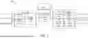


Sources:
- United States Patent and Trademark Office - verify current appl. status at the USPTO↗
Recent applications in this class:
- » 20260179197 2026-06-25
IMAGE GENERATION USING ONE OR MORE NEURAL NETWORKS - » 20260179195 2026-06-25
STORING A MEDICAL IMAGE - » 20260179194 2026-06-25
DEVICES TO PERFORM VIDEO STREAM TRANSFORMATIONS - » 20260179193 2026-06-25
IMAGE PROCESSING - » 20260179192 2026-06-25
IMAGE PROCESSING METHOD AND APPARATUS, ELECTRONIC DEVICE, AND STORAGE MEDIUM - » 20260170620 2026-06-18
IMAGE PROCESSING METHOD - » 20260170619 2026-06-18
Reducing Noise in Video Frames - » 20260170618 2026-06-18
GENERATING NON-DESTRUCTIVE SYNTHETIC LENS BLUR WITH IN-FOCUS EDGE RENDERING - » 20260170617 2026-06-18
INFORMATION PROCESSING APPARATUS, INFORMATION PROCESSING METHOD, AND NON-TRANSITORY COMPUTER-READABLE STORAGE MEDIUM - » 20260162232 2026-06-11
MITIGATING STABILIZATION EFFECTS TO RESTORE NATURAL MOTION IN VIDEO FRAMING