VACUUM STEAMER
US20260182809A1
2026-07-02
19/410,668
2025-12-05
Smart Summary: A hand-held vacuum steamer combines steam and suction in one device. It has a steam outlet at the front for releasing steam and an air intake at the top for drawing in air. The steam generator produces steam that travels through a path to the outlet. A fan creates airflow that connects the air intake to an outlet on the side, pushing air out during use. This design allows for effective steaming and cleaning in one tool. 🚀 TL;DR
Abstract:
A hand-held vacuum steamer with a front portion including a steam outlet at a first surface of a lower portion of the front portion and an air intake for a suction system at a second surface of an upper portion of the front portion, a steam generator for selectively generating steam and delivering steam to the steam outlet by way of a steam flow path, where the suction system includes a fan motor operatively connected with the power circuit for selectively driving a fan that creates an air flow path that fluidly connects the air intake to an air outlet by way of the air flow path, and where the air outlet is located on one or more side portions of the head proximate to the rear portion thereof, such that air is ejected laterally from the suction system during operation.
Inventors:
- Vignesh Manikandan Pirathaban 6 🇺🇸 Madison, WI, United States
- Firdaus Sameer Nandoliya 3 🇺🇸 Verona, WI, United States
- Fang Guohong 1 🇨🇳 Ningbo, China
- Ma Dengliang 1 🇨🇳 Ningbo, China
Applicant:
Interested in similar patents?
Get notified when new applications in this technology area are published.
Classification:
A47L11/4044 » CPC main
Machines for cleaning floors, carpets, furniture, walls, or wall coverings; Parts or details of machines not groups - , , e.g. handles, arrangements of switches, skirts, buffers, levers; Parts or details of the surface treating tools Vacuuming or pick-up tools; Squeegees
A47L11/34 » CPC further
Machines for cleaning floors, carpets, furniture, walls, or wall coverings Machines for treating carpets in position by liquid, foam, or vapour, e.g. by steam
A47L11/40 IPC
Machines for cleaning floors, carpets, furniture, walls, or wall coverings Parts or details of machines not groups - , , e.g. handles, arrangements of switches, skirts, buffers, levers
Description
CROSS-REFERENCE TO RELATED APPLICATIONS
This application claims priority to and the benefit of Chinese Patent Application No. 2024119991921, filed Dec. 31, 2024 and entitled VACUUM STEAMER and also claims priority to and the benefit of Chinese Patent Application No. 2025114964015, filed Oct. 20, 2025 and entitled VACUUM STEAMER, the contents of which are incorporated herein by reference in their entireties.
TECHNICAL FIELD
The present application relates to steamers, and more particularly to electrically-powered hand-held steamers
BACKGROUND
Steamers can be hand-held electrically heated devices that receive water in a
reservoir and that heat and convert that water to gaseous steam within a boiler or steam generator on demand for application, e.g., to clothes, fabrics, and the like. Irons can produce steam, but are intended to be used horizontally and rely primarily on a heated metal soleplate in order to smooth fabrics or the like. Hand-held steamers, in contrast, are typically operated in an upright or vertical manner, such as to be used on articles such as hanging clothes, and may or may not be used in direct contact with articles to be heated during operation. During steaming operation, a flow of steam is expelled from such a steamer.
Portable hand-held steamers can be provided with an on-board water reservoir, in contrast the steam stations, which can have a steamer head connected to a large base station via a hose, and where the base station includes operative steam generation features, such as a boiler and the water reservoir.
SUMMARY
Aspects of the invention described herein are directed to hand-held steamers that are provided in a portable, all-in-one unit. The present invention introduces improved steamer operation by employing a suction function with an intake located near a steam output. The result is a counteracting suction force to that of expelled steam on an article to be steamed. The improved portable steamer further discharges air resulting from the suction feature laterally and away from a user, such as by vents provided in the sides of the rear portion of the steamer.
Aspects of the invention described herein are directed to hand-held steamers that are provided in a portable, all-in-one unit. The present invention introduces improved steamer operation by employing a suction function with an intake located near a steam output. The result is a counteracting suction force to that of expelled steam on an article to be steamed. The improved portable steamer further discharges air resulting from the suction feature laterally and away from a user, such as by vents provided in the sides of the rear portion of the steamer.
The present invention even further provides for a shrouded, air-moving fan that operatively causes air from the suction system to pass around and through the shroud of the fan before being caused to exit laterally via the side exits from an air flow path of the suction system. Also provided herein are embodiments in which one or more seals are utilized at various interfaces or joints between components so as to at least partially isolate a flow or compartment from at least another flow or compartment or to make a particular flow or compartment substantially fluid-tight at one or more joints or interfaces, e.g., to optimize operational aspects or extend a useful life of a steamer.
The result is a compact and portable hand-held steamer with operational advantages, such as a suction effect that offsets a proximate repulsion by the steam output, and that further improves air flow and a direction of air ejection from the steamer head during operation. A more convenient and more pleasant steaming operation and steamer ownership experience results.
According to a first embodiment of the present disclosure, a hand-held vacuum steamer is disclosed. According the first embodiment, the head-held vacuum steamer includes a housing including a base and a head that are connected with one another by a graspable handle. Still according to the first embodiment, the head includes a front portion, a rear portion, and one or more side portions, the front portion including a steam outlet at a first surface of a lower portion of the front portion and an air intake at a second surface of an upper portion of the front portion. The head-held vacuum steamer also includes a steam delivery system including an internal water reservoir that is fluidly connected to a steam generator provided within the housing by way of a water flow path including a water pump operatively connected with a power circuit for moving water along the water flow path from the internal water reservoir to the steam generator, the steam generator operatively connected with the power circuit for selectively generating steam and delivering steam to the steam outlet by way of a steam flow path. The hand-held vacuum steamer also includes a suction system including a fan motor operatively connected with the power circuit for selectively driving a fan that creates an air flow path that fluidly connects the air intake to an air outlet by way of the air flow path, where the air outlet is located on one or more side portions of the head proximate to the rear portion thereof, such that air is ejected laterally from the suction system during operation. Still according to the first embodiment, the water pump, the steam generator, and the fan motor are selectively operable by one or more controls for operating the vacuum steamer so as to deliver steam from the front portion of the head below a suction generated at the front portion of the head at the air intake.
According to a second embodiment of the present disclosure, a method of using a hand-held vacuum steamer is disclosed. According to the second embodiment, the method includes moving water along a water flow path from an internal water reservoir to a steam generator. The method also includes generating steam from the water using the steam generator. The method also includes delivering the generated steam to a steam outlet at a front portion of a steamer head by way of a steam flow path. The method also includes creating a suction at an air intake at an upper part of the front portion of the steamer head using an air flow path that fluidly connects the air intake to an air outlet using a fan motor driving a fan, where the air outlet is located on one or more side portions of the head such that air is ejected laterally from the head during operation. The final also includes positioning and/or moving the steamer head near an article to be steamed.
According to a third embodiment of the present disclosure a hand-held vacuum steamer is disclosed. According to the third embodiment, the head-held vacuum steamer includes a housing including an interior, a base, and a head, where the base and head are connected with one another by a graspable handle. The head includes a front portion, a rear portion, and one or more side portions, the front portion including a steam outlet at a first surface of a lower portion of the front portion and an air intake at a second surface of an upper portion of the front portion. Also according to the third embodiment, the head-held vacuum steamer includes a steam delivery system including an internal water reservoir that is fluidly connected to a steam generator provided within the housing by way of a water flow path including a water pump operatively connected with a power circuit for moving water along the water flow path from the internal water reservoir to the steam generator, the steam generator operatively connected with the power circuit for selectively generating steam and delivering steam to the steam outlet by way of a steam flow path. Also according to the third embodiment, the head-held vacuum steamer includes a suction system including a fan motor operatively connected with the power circuit for selectively driving a fan that creates an air flow path that fluidly connects the air intake to an air outlet by way of the air flow path, where the air outlet is located on one or more side portions of the head proximate to the rear portion thereof, such that air is ejected laterally from the suction system during operation. Also according to the third embodiment, the water pump, the steam generator, and the fan motor are selectively operable by one or more controls for operating the vacuum steamer so as to deliver steam from the front portion of the head below a suction generated at the front portion of the head at the air intake, and where at least one of the front portion, the rear portion, and the suction system is provided with a substantially water-tight seal at an interface with at least the interior of the housing to enhance isolation of the air flow path from the housing interior.
These and various other features and advantages will be apparent from a reading of the following detailed description.
BRIEF DESCRIPTION OF THE DRAWINGS
The present invention will be further explained with reference to the appended Figures, wherein like structure is referred to by like numerals throughout the several views, and wherein:
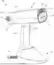
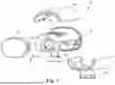
FIG. 1 is a front perspective view of a first embodiment of a hand-held steamer, according to various embodiments.
FIG. 2 is a rear perspective view of the hand-held steamer of FIG. 1.
FIG. 3 is a front close-up view of the head of the hand-held steamer of FIG. 1.
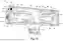
FIG. 4 is a side cross-sectional view of various components of a base of the hand-held steamer of FIG. 1.
FIG. 5 is a side cross-sectional view of various components of the head of the hand-held steamer of FIG. 1.
FIG. 6 is a partial exploded side view of various components of the head of the hand-held steamer of FIG. 1.
FIG. 7 is a partial exploded rear perspective view of the head of the hand-held steamer of FIG. 1.
FIG. 8 is a partially exploded front perspective view of various components of the head of the hand-held steamer of FIG. 1.
FIG. 9 is a cross-sectional view of the motor of the hand-held steamer of FIG. 1.
FIG. 10A is a three-quarters view of a steam chamber of the hand-held steamer of FIG. 1.
FIG. 10B is a three-quarters view of the steam chamber of FIG. 10A with certain components removed.
FIG. 11 is a front perspective view of a second embodiment of a hand-held steamer.
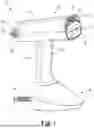
FIG. 12 is a rear perspective view of the hand-held steamer of FIG. 11.
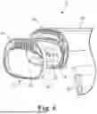
FIG. 13 is a front close-up view of the head of the hand-held steamer of FIG. 11.
FIG. 14 is a side cross-sectional view of various components of a base of the hand-held steamer of FIG. 11.
FIG. 15 is a side cross-sectional view of various components of the head of the hand-held steamer of FIG. 11.
FIG. 16 is a partial exploded side view of various components of the head of the hand-held steamer of FIG. 11.
FIG. 17 is a partial exploded rear perspective view of the head of the hand-held steamer of FIG. 11.
FIG. 18 is a partially exploded front perspective view of various components of the head of the hand-held steamer of FIG. 11.
FIG. 19 is a bottom perspective view of the hand-held steamer of FIG. 11.
FIG. 20 is a block diagram of various operative features, according to various embodiments herein.
FIG. 21 is a side cross-sectional view of various components of a head of a third embodiment of a hand-held steamer.
FIG. 22 is a partial exploded side view of various components of the head of the hand-held steamer of FIG. 21.
FIG. 23 is a partial exploded rear perspective view of the head of the hand-held steamer of FIG. 21.
DETAILED DESCRIPTION
Aspects of the invention described herein are directed to hand-held steamers that are preferably each provided as a portable, all-in-one unit.
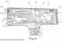
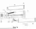
With reference to FIGS. 1-10B, a first example embodiment of a hand-held vacuum steamer 10 is shown. The hand-held vacuum steamer 10 is generally composed of a head 12, a handle 14, and a base 16, and includes an operative steam delivery system and related aspects and an operative suction system and related aspects. The head 12 of the steamer 10 is provided with air flow, water flow, and steam flow paths and features, as shown and described below. The head 12 can include a head housing 18 with a front portion 22, a rear portion 23, and side portions 30 for creating an enclosure. The front portion 22 of the housing 18 can include a first surface 24 which can comprise a plate (e.g., a metal plate), provided with steam outlet(s) (e.g., output openings) 26 sized and arranged according to various steaming aspects. The front portion 22 of the housing 18 also preferably includes, as shown, a second surface 25 provided with air intake slots 28. In various embodiments, the first and second surfaces 24 and 25, are both at the front portion 22, and can together form an operative front steaming surface. Optionally, the first surface 24 and the second surface 25 are substantially co-planar. At or proximate the rear portion 23 of the housing 18 are one or more air outlets 32, preferably near the one or more side portions 30 proximate the rear portion 23 of the housing 18.
As shown in FIG. 1, the handle 14 is preferably attached between the head 12 and the base 16, and is preferably configured to be grasped by a user for steaming operation, and can be provided with the one or more controls 20, as shown. The controls 20, which can include and/or be coupled with a power circuit (e.g., controller 212 of FIG. 20), can optionally include a power control, a temperature control, a steaming control, a water pump control, and/or any other suitable controls. Optionally integrally formed or formed of various separate components (e.g., of plastic or other materials), the base 16, positioned below the handle 14, preferably includes a reservoir 34 as shown in FIG. 4 within the base 16 for holding water and an operative power connection 36. The power connection 36 can be a corded connection to mains power, a battery internal to the steamer 10, or any other suitable power source. Also preferably included in the base 16 can be a water pump 40 for moving stored water from the reservoir 34 (see, e.g., FIG. 4) to a heated steam generator or boiler unit 51, e.g., including an electrically heated steam chamber 42 as shown preferably within the head 12 in FIG. 5, with details of a steam chamber 42 of the boiler unit 51 shown in FIG. 10A, and 10B. Steam can be produced by the steam chamber 42, e.g., on demand by the user using the controls 20. The steam chamber 42 can be provided with an electric heating element 45 (see, e.g., FIGS. 10A and 10B), optionally integrated therewith, such as a resistive heating element configured to heat the steam chamber 42 and thus heat and/or boil water within the steam chamber 42 of the boiler unit 51 to produce steam.
In more detail, as shown in FIG. 5 the steamer 10 can be provided with various fluid paths, including an air flow path 48 of a suction system, a steam flow path 46 of a steam delivery system, and a water flow path 44 of the steam delivery system. Each path can comprise one or more sub-paths or path branches within a portion of the respective path.
The air flow path 48, as shown best in FIG. 5, can be at least partially contained within an air flow chamber 49 (or series of chambers) within an optionally tapered air flow housing 50 in the head 12 of the steamer 10. The air flow path 48 can begin at the air intake 28, and air can be pulled through a passage behind the surface 25, and then can reach a fan assembly 61 operatively connected to a motor assembly 60 (see, e.g., FIGS. 7 and 9). The air flow housing 50 can be tapered, as shown, to a smaller cross-sectional area as it preferably passes closer to the rear 23 of the head 12. Finally, the air flow path 48 can terminate proximate the rear 23, as the air preferably enters a rear air chamber plenum 53 before exiting laterally through one or more air outlet openings 32, e.g., to ambient. Preferably, the openings 32 are configured to discharge outlet air laterally and to the sides 30 of the head 12, and thus the outlet air from the air flow path 48 can be directed away from a user.
Turning now to FIG. 9, the air flow path 48 can pass through a portion of fan shroud, as can be provided by the motor housing 70 and/or the air flow housing 50, within the head 12, and then can proceed to the rear 23 of the steamer head 12 (see also FIG. 7). The shroud can surround the air flow path 48 (e.g., optionally forming an axial impeller) of the fan assembly 61. Still referring to FIG. 9, one or more fan blades 62 of the fan assembly 61 can define or provide one or more rotating openings through which the air flow path 48 can pass.
The water flow path 44, which can preferably be composed of pre-pump section 44A and post-pump section 44B (collectively, water flow path 44), is shown best in FIGS. 4 and 5. As shown, the water flow path 44 can form part of a steam delivery system and can begin at the internal water reservoir 34 shown in the base 16 of the steamer 10. The internal water reservoir 34 is shown in the base 16, but can be located anywhere within the steamer 10. A tubed water intake 41 can be provided in the reservoir 34, and an electric pump 40 can be coupled to the power circuit, and can selectively cause water to flow through the water flow path 44 upward from the base 16, through the handle 14, and eventually to reach the heated steam chamber 42 of the boiler unit 51 within the head 12 and housing 18 of the steamer 10. Preferably, the pump selectively 40 causes water to flow to the steam chamber 42 via the water inlet 47 thereof (see, e.g., FIG. 10A), from water flow path 44, preferably upon user demand, and/or when all water within the steam chamber 42 has been converted to gaseous steam.
In preferable embodiments, once the water from the reservoir 34 follows the water flow path 44 and is converted to steam, the steam flow path 46 of the steam delivery system can begin. In other words, the water flow path 44 and the steam flow path 46 can form a single flow path circuit in various embodiments. In the steam chamber 42, as the water is preferably converted to gaseous steam, a flow of steam can be created, such that steam can flow out from the steam outlets 26 of the surface 24 at the front 22 of the head 12. Thus, during operation, such as selectively initiated by a user through controls 20, steam can be caused to exit the front 22 of the steamer 10, such as to apply the steam to an article, e.g., hanging clothes or the like. During operation, such as positioning and/or moving the steamer near the article to be steamed, at least some repulsive force can be exerted on the article to be steamed by the steam in various examples as it is being expelled from the front 22. The steaming repulsive force can be at least partially offset by a suction attractive force relative to the article.
The size of the outlets 26 of the front steam exit for steam can be configured to be larger or smaller in diameter, e.g., to provide higher or lower steam pressure. For example, the outlets 26 can be configured such that steam exit flow avoids undue steam being sucked into the air flow path 48. In various preferred embodiments, the air flow path 48 and the steam flow path 46 are substantially fluidically separate. Also as shown in the first embodiment, the outlets 26 are provided in generally horizontally extending channels or recessed grooves of the first surface 24 of the front 22 of the head 12. Optionally, the first surface 24 can be heated, such as by electrical resistive heating and/or by being heated by steam flowing therethrough and/or in contact therewith. The first surface 24 is therefore optionally a heated plate that can be configured to contact the article to be steamed and/or pressed.
As described above, a localized, negative-pressure, suction effect preferably results from the air flow path 48 having its intake 28 at the surface 25 of the front portion 22 of the steamer head 12. Also as shown, the air intake 28 (see, e.g., FIG. 1) and resulting suction can be positioned at an upper portion of the steamer head front portion 22, and the steam outlets 26 can be provided at a lower portion of the steamer head front portion 22. As discussed above, the suction can create a force on the article that at least partially offsets the force applied to the article by the expelled steam. As shown, the air intake 28 and the steam outlets 26 of the first surface 24 can thus be in close proximity, resulting in an easy-to-use steaming experience in which a steaming repulsion (pushing) effect can be at least partially offset by a corresponding air intake, suction (pulling) effect at the operative front portion 22 surface(s) of the hand-held steamer unit 10. In various optional embodiments, steam is thus provided to the article through the outlets 26 of the heated first surface 24, which is also optionally contacted or pressed to the article to be steamed. The suction aspects are preferably optimized in terms of location and surface area such that a balanced suction and air flow preferably avoids steam/water accumulation and/or condensation in or on the various parts of the steamer unit 10.
In preferable embodiments, the air and steam flow paths (48, 46) are also optimized to achieve optimal pressure (suction) for the steaming, e.g., of the garment or article. The flow paths and resulting flows, e.g., volume and speed of fluid flow, including volumetrics, can be further be optimized, e.g., for preferable motor assembly 60 aspects, such as nominal motor RPM, load, etc.
In preferable embodiments, e.g., steamer 10, steam is preferably provided or expelled from the steamer 10 at a higher pressure than the corresponding air suction or negative pressure as a negative pressure amplitude (or vacuum, e.g., in mmHg). A benefit of a greater force and quantity of steam output relative to air input is to promote the chances that a certain quantity of steam provided exceeds that steam that may be sucked into and removed by the air intake, and thus ensuring that enough steam remains in order to operatively smooth the article to be steamed. Therefore, preferably, steam flow is selected to be a higher flow than the corresponding air flow suction such that the steam flow reaches the article to be steamed even when suction is activated.
With reference to FIGS. 6-8, shown are certain partially exploded views of various components of the head 12 of the hand-held steamer 10. As shown in FIG. 6, for example, the housing 18 can include an upper portion 18A, a lower portion 18B, and a rear portion 18C, which can optionally be joined together to form at least a portion of the housing 18. A portion of the air flow path 48 as it passes the motor assembly 60 is shown in FIG. 7. As shown, in FIG. 8, the air intake slots 28 can be sized and shaped (generally vertically oriented, as shown) to optimize pressure/suction. Also shown in FIG. 8 is an optional air intake filter 54 that can be configured at the air intake of the air flow path 48, the filter 54 being preferably configured to protect internal parts, such as the motor assembly 60, within the air flow path 48, e.g., from dust, debris, lint) that can get drawn or pulled inside the steamer 10 during suction operation. It is understood that some steam can be drawn in through the air flow path 48 during operation. Even further, as shown, an intake ring 52, preferably comprising slots 28, can be selectively attachable and detachable from the head 12 at the front portion 22, e.g., for assembly, cleaning, or removal of various parts, such as the filter 54 (or optionally an element thereof). The filter 54 is optionally removably supported in and by the housing 18. Optionally, the intake ring 52 can be held to the head 12 by a snap-type attachment, friction-fit, magnets, or any other suitable attachment mechanism.
Additional details of the first embodiment are also shown in FIGS. 9, 10A, and 10B. As shown in FIG. 9 in additional detail, the motor assembly 60 can include a waterproof or water-resistant brushless direct current (BLDC) electric motor. The motor assembly 60 preferably also comprises a motor housing 70, a motor shaft 72 with rotor 80, a bearing 74, and a motor frame 76 holding a stator 78. As shown, the BLDC motor assembly 60 preferably comprises a back seal 66 configured to provide a water-tight seal to prevent water and/or steam from entering live parts of the motor assembly 60. Thus, a back of the motor assembly 60 is preferably sealed with seal 66 so steam does not infiltrate the motor assembly 60. Also shown in the presented embodiment is a front seal 68. The front 68 and/or rear back seals 66 are preferably provided to avoid water or condensation entering any live electrical or electronic parts, such as of the motor assembly 60. Also as shown, a gap 64 is preferably provided to keep metal parts spaced from plastic parts of the motor assembly 60. As shown in FIG. 7, the motor assembly 60 can be provided with an operative connecting conduit 55, e.g., for connecting the motor assembly 60 to various operative controls, and the like. The motor assembly 60 can optionally include an alternating current (AC), direct current (DC), or any other suitable type of electric motor. When power is provided to the motor assembly 60, the rotor 80 is caused to be rotated relative to the stator 78 such that the shaft 72 and the fan blade 62 of the fan assembly 61 is caused to be rotated and air is caused to flow according to the air flow path 48.
FIGS. 10A and 10B show the example boiler unit 51 with a steam chamber 42 separate from other components of the steamer 10 and in additional detail. A heating element 45 as shown is optionally at least partially integrated into the steam chamber 42, e.g., for operatively heating and steaming water. The steam chamber 42 and heating element 45 can be operatively connected to the power circuit of the steamer 10. Also as shown in FIG. 10B, the steam flow path 46 can follow various labyrinthine turns between the water flow path (44, see also FIG. 5) that enters the steam chamber 42 at a steam chamber water connection 47 of the water flow path 44 (see FIG. 10A), and exits the steam chamber 42 via steam outlets 26. within the steam chamber 42 so as to more completely convert liquid water to steam within the steam chamber 42.
FIGS. 10A and 10B show the example boiler unit 51 with a steam chamber 42 separate from other components of the steamer 10 and in additional detail. A heating element 45 as shown is optionally at least partially integrated into the steam chamber 42, e.g., for operatively heating and steaming water. The steam chamber 42 and heating element 45 can be operatively connected to the power circuit of the steamer 10. Also as shown in FIG. 10B, the steam flow path 46 can follow various labyrinthine turns between the water flow path (44, see also FIG. 5) that enters the steam chamber 42 at a steam chamber water connection 47 of the water flow path 44 (see FIG. 10A), and exits the steam chamber 42 via steam outlets 26. within the steam chamber 42 so as to more completely convert liquid water to steam within the steam chamber 42.
FIGS. 11-19 show a second embodiment of a hand-held vacuum steamer 110 similar to steamer 10.
Similar to steamer 10, the hand-held vacuum steamer 110 is generally composed of a head 112, a handle 114, and a base 116, and includes an operative steam delivery system and related aspects and an operative suction system and related aspects. The head 112 of the steamer 110 is provided with air flow, water flow, and steam flow paths and features, as shown and described below. The head 112 can include a head housing 118 with a front portion 122, a rear portion 123, and side portions 130 for creating an enclosure. The front portion 122 of the housing 118 can include a first surface 124 which can comprise a plate (e.g., a metal plate), provided with steam outlet(s) (e.g., output openings) 126 sized and arranged according to various steaming aspects. The front portion 122 of the housing 118 also preferably includes, as shown, a second surface 125 provided with air intake slots 128. In various embodiments, the first and second surfaces 124 and 125, are both at the front portion 122, and can together form an operative front steaming surface. Optionally, the first surface 124 and the second surface 125 are substantially co-planar. At or proximate the rear portion 123 of the housing 118 are one or more air outlets 132, preferably near the one or more side portions 130 proximate the rear portion 123 of the housing 118. Optionally, the first surface 124 can be heated, such as by electrical resistive heating and/or by being heated by steam flowing therethrough and/or in contact therewith. The first surface 124 is therefore optionally a heated plate that can be configured to contact an article to be steamed and/or pressed.
As shown in FIG. 11, the handle 114 is preferably attached between the head 112 and the base 116, and is preferably configured to be grasped by a user for steaming operation, and can be provided with the one or more controls 120, as shown. As shown on steamer 110, a gripping texture 119 can be provided on a handle 114 thereof. Additionally, and also as shown, slotted grips 121 on the water reservoir 134 housing of base 116 to grip for removal, e.g., using a user's finger nails.
Also according to the second embodiment of steamer 110, controls 120 are provided, which can include and/or be coupled with a power circuit (not shown), can optionally include a power control, a temperature control, a steaming control, a water pump control, and/or any other suitable controls. The controls 120 preferably include two or more buttons are provided on the handle 114. As shown, a top button of controls 120 is configured to release steam on demand. In some configurations, a user can either briefly press or hold the top button of the controls 120 for an extended period. A brief press of the top button provides for on/off toggling of continuous steaming operation (until pressed again, etc.), and a press-and-hold action results in on-demand steaming until the button is released by the user. Various settings can be provided for operation of the steamer 110. For example, the first embodiment steamer 10 may provide for a single setting for suction, while the second embodiment steamer 110 can provide two or more options for suction level (e.g., in mmHg measured at the front 122). Steaming using steamer 110 preferably provides for consistent (single level) steaming, whereas suction can preferably be set to various levels and settings, such as off, low, or high. In various configurations and settings, the user can use the steamer 110 for steam only or can instead use a steam-plus-vacuum setting. Each of the settings can be configured for low, high, or any variation thereof. As shown, the top button of the controls 120 can allow for a sliding operation of the button. As shown, a slider switch is provided at controls 120 to select the suction level for operation in the second embodiment of the steamer 110. For example, sliding the button can change a setting from low, to high, to off. Other variations and combinations are also contemplated, and any described control aspects of controls 120 can be applied to the steamer 10 as applicable, and vice-versa.
Optionally integrally formed or formed of various separate components (e.g., of plastic or other materials), the base 116, positioned below the handle 114, preferably includes a reservoir 134 as shown in FIG. 14 within the base 116 for holding water and an operative power connection 136. The power connection 136 can be a corded connection to mains power, a battery internal to the steamer 110, or any other suitable power source. Also preferably included in the base 116 can be a water pump 140 for moving stored water from the reservoir 134 (see, e.g., FIG. 14) to a heated steam generator or boiler unit 151, preferably similar to boiler unit 51 shown in FIGS. 10A and 10B. Steam can be produced by the boiler unit 151, e.g., on demand by the user using the controls 120, as described above.
In more detail, the steamer 110 can be provided with various fluid paths, including an air flow path 148 of a suction system, a steam flow path 146 of a steam delivery system, and a water flow path 144 of the steam delivery system. Each fluid or other path can comprise one or more sub-paths or path branches within a portion of the respective path. See, e.g., FIG. 15.
The air flow path 148, as shown best in FIG. 15, can be at least partially contained within an air flow chamber 149 (or series of chambers) within an optionally smoothly tapered air flow housing 150 in the head 112 of the steamer 110. The air flow path 148 can begin at the air intake 128, and air can be pulled through a passage behind the surface 125, and then can reach the motor assembly 160 and fan assembly 161 (see, e.g., motor assembly 60 and fan assembly 61 of FIG. 9) and surrounding shroud (e.g., optionally forming an axial impeller) of the motor assembly 160. As shown, the air flow path 148 can pass through at least a portion of the fan shroud, as can be provided by the motor housing (see, e.g., motor housing 70 of FIG. 9) and/or the air flow housing 150, within the head 112, and then can proceed to the rear 123 of the steamer head 112. The air flow housing 150 can be tapered, as shown, to a smaller cross-sectional area as it preferably passes closer to the rear 123 of the head 112. Motor assembly 160 can be similar or the same as motor assembly 60, including various aspects described above. Finally, the air flow path 148 can terminate proximate the rear 123, as the air preferably enters a rear air chamber plenum 153 before exiting laterally through one or more air outlet openings 132, e.g., to ambient. Preferably, the openings 132 are configured to discharge outlet air to the sides 130 of the head 112, and thus the outlet air from the air flow path 148 can be directed away from a user.
As shown, the steamer 110 can beneficially provide an alternative configuration that provides an alternative air flow chamber 149 configured for smooth, tapered, laminar flow of air passing internally through the air flow chamber 149 of the air flow path 148 during operation. The disclosed air flow chamber 149 minimizes sudden and sharp turns, such as ups or downs, in the air flow path 148, and provides gradual curvature for the air flowing therethrough. Improving effective laminar flow within the air flow chamber 149 can reduce various pressures during operation, and can thus reduce resulting sound and noise during operation (e.g., emitted from motor assembly 160). As a result of lower noise compared to existing configurations, disclosed embodiments provide for relatively higher power and higher suction per emitted sound. Thus, for a given sound level, a greater amount of motor speed and/or suction were able to be achieved.
The water flow path 144, which can preferably be composed of pre-pump section 144A and post-pump section 144B (collectively, water flow path 144), is shown best in FIGS. 14 and 15. As shown, the water flow path 144 can form part of a steam delivery system and can begin at the internal water reservoir 134 shown in the base 116 of the steamer 110. The internal water reservoir 134 is shown in the base 116, but can be located anywhere within the steamer 110. A tubed water intake 141 can be provided in the reservoir 134, and an electric pump 140 can be coupled to the power circuit, and can optionally cause water to flow through the water flow path 144 upward from the base 116, through the handle 114, and eventually to reach the heated boiler unit 151 (preferably including a steam generator therein) within the head 112 and housing 118 of the steamer 110. Preferably, the pump 140 causes water to flow to the boiler unit 151 via the water inlet 143 thereof, from water flow path 144, preferably upon user demand, and/or when all water within the boiler unit 151 has been converted to gaseous steam.
In preferable embodiments, once the water from the reservoir 134 follows the water flow path 144 and is converted to steam, the steam flow path 146 of the steam delivery system can begin. In other words, the water flow path 144 and the steam flow path 146 can form a single flow path circuit in various embodiments. In the boiler unit 151, as the water is preferably converted to gaseous steam, a flow of steam can be created, such that steam can flow out from the steam outlets 126 of the surface 124 at the front 122 of the head 112. Thus, during operation, such as selectively initiated by a user through controls 120, steam can be caused to exit the front 122 of the steamer 110, such as to apply the steam to hanging clothes or the like. During operation, some repulsive force can be exerted on the article to be steamed by the steam in various examples as it is being expelled from the front 122. The size of the outlets 126 of the front steam exit for steam can be configured to be larger or smaller in diameter, e.g., to provide higher or lower steam pressure. For example, the outlets 126 can be configured such that steam exit flow avoids undue steam being sucked into the air flow path 148. In various preferred embodiments, the air flow path 148 and the steam flow path 146 are fluidically separate.
The second embodiment of steamer 110 has an alternative front portion 122 configuration, as shown, among other variations. As shown in FIG. 13, one or more S-shaped grooved steam outlets 126 are primarily vertically-oriented. The horizontal orientation of apertures 128 of the second embodiment also provides for reduced size of the apertures 128, where can beneficially reduce inconsistencies on pressure for each suction hole, reducing water/steam lines on clothes, and the like.
In preferable embodiments, e.g., steamer 110, steam is preferably provided or expelled from the steamer 110 at a higher pressure than a magnitude of the corresponding air suction. A benefit of a greater force and quantity of steam output relative to air input is to promote the chances that a certain quantity of steam provided exceeds what is sucked into and removed by the air intake, and thus ensuring that enough steam remains in order to operatively smooth the article to be steamed. Therefore, preferably, steam flow is provided at a higher rate than the suction so an operative steam flow remains even when the suction function is activated.
As described above, a localized, negative-pressure, suction effect preferably results from the air flow path 148 having its intake 128 at the surface 125 of the front portion 122 of the steamer head 112. Also as shown, the air intake 128 (see, e.g., FIG. 11) and resulting suction can be positioned at an upper portion of the steamer head front portion 122, and the steam outlets 126 can be provided at a lower portion of the steamer head front portion 122. The suction can create a force on the article that at least partially offsets the force applied to the article by the expelled steam. As shown, the air intake 128 and the steam outlets 126 can thus be in close proximity, and can result in an easy-to-use steaming experience in which a steaming repulsion (pushing) effect can be at least partially offset by a corresponding air intake, suction (pulling) effect at the operative front portion 122 surface(s) of the hand-held steamer unit 110. In various optional embodiments, steam is thus provided to the article through the outlets 126 of the heated first surface 124, which is also optionally contacted or pressed to the article to be steamed. The suction aspects are preferably optimized in terms of location and surface area such that a balanced suction and air flow preferably avoids steam/water accumulation and/or condensation in or on the various parts of the steamer unit 110.
In preferable embodiments, the air and steam flow paths (148, 146) are optimized to achieve optimal pressure (suction) for the steaming, e.g., of the garment or article. The flow paths and resulting flows, e.g., volume and speed of fluid flow, including volumetrics, can be further be optimized, e.g., for preferable motor assembly 160 aspects, such as nominal motor RPM, load, etc.
In preferable embodiments, the air and steam flow paths (148, 146) are optimized to achieve optimal pressure (suction) for the steaming, e.g., of the garment or article. The flow paths and resulting flows, e.g., volume and speed of fluid flow, including volumetrics, can be further be optimized, e.g., for preferable motor assembly 160 aspects, such as nominal motor RPM, load, etc.
With reference to FIGS. 16-18, shown are certain partially exploded views of various components of the head 112 of the hand-held steamer 110. As shown in FIG. 16, for example, the housing 118 can include an upper portion 118A, a lower portion 118B, and a rear portion 118C, which can optionally be joined together to form at least a portion of the housing 118. A portion of the air flow path 148 as it passes the motor assembly 160 is shown in FIG. 17. As shown, in FIG. 18, the air intake slots 128 can be sized and shaped (generally horizontally-oriented, as shown) to optimize pressure/suction. Also shown in FIG. 18 is an optional air intake filter 154 that can be configured at the air intake of the air flow path 148, the filter 154 being preferably configured to protect internal parts, such as the motor assembly 160, within the air flow path 148, e.g., from dust, debris, lint) that can get drawn or pulled inside the steamer 110 during suction operation. It is understood that some steam can be drawn in through the air flow path 148 during operation. Even further, as shown, an intake ring 152, preferably comprising slots 128, can be selectively attachable and detachable from the head 112 at the front portion 122, e.g., for assembly, cleaning, or removal of various parts, such as the filter 154 (or optionally an element thereof). The filter 154 is optionally removably supported in and by the housing 118. Optionally, the intake ring 152 can be held to the head 112 by a snap-type attachment, friction-fit, magnet(s), or any other suitable removable attachment mechanism.
Also as shown on steamer 110, and with particular reference to FIG. 19, an integrated brush holder 156 and brush 157 are optionally provided on the base 116 of the steamer 110. As shown, a complementary shaped brush holder 156 with an indentation to receive a user finger is provided on the base 116 of the steamer 110. The brush 157 can be provided so that the user can clean the filter 154 when the intake ring 152 of the front portion 122 is removed. The brush 157 can be held to the base 116 using opposing snap-fit features 159 as shown, or any other method of attachment. The brush 157 can be provided with bristles 158 configured to cleaning a filter 154 or any other feature of the steamer 110. The intake ring 152 is preferably magnetically held to the unit, and a magnet feature (e.g., one or more permanent magnets; not shown) can be provided on the front portion 122 and/or the unit for connection to the intake ring 152. Other, non-magnet, methods of attaching the intake ring 152 to the main unit are also contemplated.
FIG. 20 is a block diagram 200 of various operative features of various embodiments of a hand-held steamer described herein, such as hand-held steamer 10 or hand-held steamer 110, described above.
As shown, a power source 210 can be provided, and a controller 212 can be connected to the power source 210. The controller 212, which can further comprise a power circuit, can include an operatively connected processor and a memory. The controller 212 can be operatively connected to a steam/water system 214 and an air/suction system 224.
The steam/water system 214 preferably comprises a steam generator 216, a water reservoir 218, a water pump 220, and a steam outlet 222. As shown, the steam outlet 222 can be operatively associated with an operative vacuum steamer surface 232. The air/suction system 224 preferably includes a shrouded fan 226, an air outlet 228, and an air intake 230. As shown, the air intake 230 can also be operatively associated with the operative vacuum steamer surface 232, optionally above, below, and/or proximate the steam outlet 222. As described herein, the operative vacuum steamer surface 232 can be used to apply steam to fabrics, such as clothes, textiles, or the like with a beneficial ease of use.
FIGS. 21-23 show a third embodiment of a hand-held vacuum steamer 310 similar to steamers 10 and 110.
The steamer 310 is understood to be substantially similar to steamer 110 in particular, except as noted below. The steamer 310 is generally composed of a head 312, a handle 314, and a base 316, and includes an operative steam delivery system and related aspects and an operative suction system and related aspects described in various embodiments herein. The head 312 of the steamer 310 can be provided with air flow, water flow, and steam flow paths and features, as shown and described in other embodiments, herein. The head 312 can include a head housing 318 with a front portion 322, a rear portion 323 (associated with a rear plate 382), and side portions 330 for creating an enclosure. As shown in FIGS. 22 and 23, the housing 318 can include an upper portion 318A, a lower portion 318B, and a rear portion 318C, which can optionally be joined together to form at least a portion of the housing 318.
The front portion 322 of the housing 318 can include a first surface 324 which can comprise a plate (e.g., a metal plate), provided with steam outlet(s) (e.g., output openings) 326 sized and arranged according to various steaming aspects. The front portion 322 of the housing 318 also preferably includes, as shown, a second surface 325 provided with air intake (slots) 328. In various embodiments, the first and second surfaces 324 and 325, are both at the front portion 322, and can together form an operative front steaming surface. Optionally, the first surface 324 and the second surface 325 are substantially co-planar. At or proximate the rear portion 323 of the housing 318 are one or more air outlets 332, similar to various other embodiments. Optionally, the first surface 324 can be heated, such as by electrical resistive heating and/or heat transfer from steam flowing therethrough and/or in contact therewith. The first surface 324 is therefore optionally a heated plate that can be configured to contact an article to be steamed and/or pressed.
A graspable handle 314 is shown, which can be similar to handle 114 described above, and which can define at least a part of and/or can at least partially enclose a lower housing interior 376. As in other embodiments described above, the steamer 310 can be provided with various fluid paths. The lower housing interior is preferably fluidly separate from any of the various fluid paths, including the air flow, water flow, and steam flow paths. The lower housing interior 376 can include one or more operative components, including various electrical and/or electronic components as discussed above and shown in, e.g., FIGS. 4 and 14, which are preferably are kept dry during steamer 310 operation.
In order to keep certain components dry or to provide other advantageous effects, such as improved efficiency, the steamer 310 can beneficially include features to limit or prevent water from entering the lower housing interior 376 from the vacuum airflow, which may include generated steam. One or more additional substantially hermetic or substantially fluid-tight seals at various interfaces of the housing 318. For example, front and rear seals 378, 374, and seal (e.g., gasket) 370 are shown in FIGS. 22 and 23. As discussed above, back and front (motor) seals 66 and 68 are also contemplated. A tighter sealed, more mutually isolated, substantially air/water-tight housing or component can exhibit a number of advantages, including avoidance or reduction of water/steam intrusion into upper housing interior 372 and lower housing interior 176, and advantageously a more efficient suction and air flow during steamer 310 operation. In various embodiments, one or more substantially water-tight seals are configured to provide a substantially water-tight air-flow path that is fluidically isolated from at least the steam flow path.
For example, at least one of the front portion 322, the rear portion 323, and the suction system can be provided with a substantially water-tight seal at an interface with at least the interior of the housing 372 to enhance isolation of the air flow path (and/or steam flow path) from the housing interior 372.
A smoothly tapered air flow housing 350 can define a substantially sealed air flow chamber 349 of a suction system provided within the housing 318. The air flow housing 350 preferably comprises an upper portion 366, which can be removably attachable at a circumferential channel or groove 368 of a lower portion 369 of the housing 350 in the steamer head 312. As shown in FIG. 23, the (e.g., pressure-fit gasket) seal 370 (e.g., an upper seal) can preferably be positioned in the groove 368 formed between the upper portion 366 and the lower portion 369 of the housing 350. The seal 370 is preferably a molded single-piece unit that is configured to complement and fill a portion of the groove 368. When installed, the seal 370 can preferably provide a beneficially sealed interface between the upper portion 366 and the lower portion 369 of the housing 350, which can define an air flow path including the air flow chamber 349.
Such air flow path (e.g., similar to path 148) can begin at the air intake 328, and air can be pulled through a passage behind the surface 325, and then can reach the motor assembly 360 (see, e.g., motor assembly 60 and fan assembly 61 of FIG. 9). The air flow housing 350 can be tapered, as shown, to a smaller cross-sectional area as it preferably passes closer to the rear 323 of the head 312. Motor assembly 360 can be similar or the same as motor assembly 60, including various aspects described above.
The front seal 378 can be provided, optionally in a removable or replaceable manner, at or along a circumferential edge of a front plate support 377. The front seal 378 can be disposed at an interface between the front portion 322 and/or a plate portion 379 and the front plate support 377 and/or the steamer body 318. In this configuration, the front seal 378 preferably functions to inhibit the passage of air, water, and/or steam through the interface, thereby forming a substantially air-tight and water-tight joint at or near the front portion 322. The water-tight joint can, for example, separate the air flow path and the upper housing interior 372. The front seal 378 can be formed of an elastomeric material, gasket, O-ring, or other suitable sealing structure, and may be press-fit, adhesively bonded, threaded, or otherwise secured in place. Preferably, the rear seal 374 can be positioned at an interface between a rear support 380 and at least a portion of the steamer body 318, such as along a circumferential or perimeter region of the rear support 380, in order to provide a corresponding substantially air- and water-tight seal at or near the rear portion 323. The rear seal 374 can be formed of an elastomeric material, gasket, O-ring, or other suitable sealing structure, and may be press-fit, adhesively bonded, threaded, or otherwise secured in place. Each of the front and rear seals 378, 374 can act individually or in cooperation to prevent leakage of steam, air, or liquid through various parts of the housing 318, thereby enhancing device performance and user safety.
In operation, water/steam can potentially intrude over time into various non-operative portions of the steamer 310. Benefits of the front 378 and rear 374 seals can be to avoid fluid intrusion across an interface and into an upper housing interior 372 and/or into the lower housing interior 376, which may be open to one another or fluidly separate in various embodiments. Benefits of the seal 370 can include avoidance of water/steam intrusion into the upper housing interior 372 and/or providing a more efficient steaming operation through a less leaky air flow path within the air flow chamber 349.
By substantially and tightly sealing the chamber, the steamer 310 can maintain a pressure differential between the air flow chamber 349 and ambient atmosphere, and thus improve suction and overall steamer 310 performance. A substantially fluidically sealed configuration preferably prevents unintended leakage paths so that incoming air, liquid, or steam is drawn predominantly through the designated intake, thereby concentrating the flow and increasing intake velocity. Such sealing also improves efficiency of the motor assembly 360, as less energy is consumed compensating for leaks and more of the generated negative pressure is translated into useful suction at the air intake 328. In addition, such a sealed chamber can provide more stable and predictable operation, reducing turbulence and pressure fluctuations that may otherwise diminish cleaning or fluid-removal effectiveness.
Any of the seals or gaskets 370, 374, 378, 66, 68 can be an elastomeric (for example, rubber, silicone, nitrile, or fluorocarbon) O-ring or other suitable construction or shape. In some cases, the seals may instead be formed of a polymer such as PTFE or a fiber-reinforced or metallic gasket material, depending on the operating environment. The seals can be press-fit, threaded, or otherwise secured between adjacent portions in order to provide a tight seal at various interfaces.
The present invention has now been described with reference to several embodiments thereof. The foregoing detailed description and examples have been given for clarity of understanding only. No unnecessary limitations are to be understood therefrom. It will be apparent to those skilled in the art that many changes can be made in the embodiments described without departing from the scope of the invention. The implementations described above and other implementations are within the scope of the following claims.
Claims
What is claimed is:1. A hand-held vacuum steamer, comprising:
a housing comprising a base and a head that are connected with one another by a graspable handle;
the head comprising a front portion, a rear portion, and one or more side portions, the front portion comprising a steam outlet at a first surface of a lower portion of the front portion and an air intake at a second surface of an upper portion of the front portion;
a steam delivery system comprising an internal water reservoir that is fluidly connected to a steam generator provided within the housing by way of a water flow path including a water pump operatively connected with a power circuit for moving water along the water flow path from the internal water reservoir to the steam generator, the steam generator operatively connected with the power circuit for selectively generating steam and delivering steam to the steam outlet by way of a steam flow path; and
a suction system comprising a fan motor operatively connected with the power circuit for selectively driving a fan that creates an air flow path that fluidly connects the air intake to an air outlet by way of the air flow path, wherein the air outlet is located on one or more side portions of the head proximate to the rear portion thereof, such that air is ejected laterally from the suction system during operation,
wherein the water pump, the steam generator, and the fan motor are selectively operable by one or more controls for operating the vacuum steamer so as to deliver steam from the front portion of the head below a suction generated at the front portion of the head at the air intake.
2. The hand-held vacuum steamer of claim 1, wherein the one or more controls are located on the graspable handle portion, wherein the steam generator is positioned within the head, and wherein the water reservoir is positioned within the base.
3. The hand-held vacuum steamer of claim 1, further comprising a controller operatively connectable to a power source, wherein the controller is configured to operatively power the fan motor, the water pump, and a heating element of the steam generator.
4. The hand-held vacuum steamer of claim 1, wherein the air outlet comprises at least two air outlets comprising a first air outlet and a second air outlet, wherein the first air outlet is located at a first side portion of the head, and wherein the second air outlet is located at a second side portion of the head, opposite the first side portion.
5. The hand-held vacuum steamer of claim 1, wherein the first surface of the head comprises a heated metal plate.
6. The hand-held vacuum steamer of claim 1, wherein the first surface and the second surface are substantially co-planar.
7. The hand-held vacuum steamer of claim 1, wherein the steam outlet comprises a plurality of openings.
8. The hand-held vacuum steamer of claim 1, wherein at least one of the fan motor, the front portion, the rear portion, and the suction system is provided with a substantially water-tight seal.
9. The hand-held vacuum steamer of claim 1, further comprising a rear seal positioned at an interface between a rear support and at least a portion of the housing, wherein the rear seal is positioned along a circumferential or perimeter region of the rear support, and is configured to provide a corresponding substantially air- and water-tight seal at or near the rear portion.
10. The hand-held vacuum steamer of claim 1, wherein the air flow path and the steam flow path are fluidically separate.
11. The hand-held vacuum steamer of claim 1, wherein the steam delivery system is configured to produce steam to be applied to an article while the air intake provides suction to pull the article toward the front portion of the head, wherein the steam produced by the steam delivery system causes a repulsive force to be applied to the article, and wherein the suction system creates a suction force on the article, such that at least some of the repulsive force on the article is offset.
12. The hand-held vacuum steamer of claim 11, wherein the first surface of the head comprises a heated metal plate, and wherein the heated metal plate is configured to contact the article during operation.
13. The hand-held vacuum steamer of claim 1, wherein the air intake comprises a filter supported to the head.
14. The hand-held vacuum steamer of claim 1, further comprising a cleaning brush removably attachable to the base for storage, wherein the cleaning brush is configured to clean the filter of the head.
15. The hand-held vacuum steamer of claim 1, wherein the fan motor comprises a motor housing and one or more internal electrical or electronic parts, wherein the motor housing further comprises a motor seal configured to provide a water-tight seal to prevent water and/or steam from reaching the one or more internal electrical or electronic parts, and wherein the air flow path is configured to pass through at least a portion of the motor housing.
16. A method of using a hand-held vacuum steamer, comprising:
moving water along a water flow path from an internal water reservoir to a steam generator,
generating steam from the water using the steam generator;
delivering the generated steam to a steam outlet at a front portion of a steamer head by way of a steam flow path;
creating a suction at an air intake at an upper part of the front portion of the steamer head using an air flow path that fluidly connects the air intake to an air outlet using a fan motor driving a fan, wherein the air outlet is located on one or more side portions of the head such that air is ejected laterally from the head during operation; and
positioning and/or moving the steamer head near an article to be steamed.
17. A hand-held vacuum steamer, comprising:
a housing comprising an interior, a base, and a head, wherein the base and head are connected with one another by a graspable handle;
the head comprising a front portion, a rear portion, and one or more side portions, the front portion comprising a steam outlet at a first surface of a lower portion of the front portion and an air intake at a second surface of an upper portion of the front portion;
a steam delivery system comprising an internal water reservoir that is fluidly connected to a steam generator provided within the housing by way of a water flow path including a water pump operatively connected with a power circuit for moving water along the water flow path from the internal water reservoir to the steam generator, the steam generator operatively connected with the power circuit for selectively generating steam and delivering steam to the steam outlet by way of a steam flow path; and
a suction system comprising a fan motor operatively connected with the power circuit for selectively driving a fan that creates an air flow path that fluidly connects the air intake to an air outlet by way of the air flow path, wherein the air outlet is located on one or more side portions of the head proximate to the rear portion thereof, such that air is ejected laterally from the suction system during operation,
wherein the water pump, the steam generator, and the fan motor are selectively operable by one or more controls for operating the vacuum steamer so as to deliver steam from the front portion of the head below a suction generated at the front portion of the head at the air intake, and wherein at least one of the front portion, the rear portion, and the suction system is provided with a substantially water-tight seal at an interface with at least the interior of the housing to enhance isolation of the air flow path from the housing interior.
18. The hand-held vacuum steamer of claim 17, wherein the substantially water-tight seal comprises:
i) a rear seal positioned at an interface between a rear support and at least a portion of the housing, wherein the rear seal is positioned along a circumferential or perimeter region of the rear support, and is configured to provide a corresponding substantially air- and water-tight seal at or near the rear portion and the interior of the housing,
ii) a front seal positioned at an interface between the front portion and at least a portion of the housing, wherein the front seal is positioned along a circumferential or perimeter region of the front portion, and is configured to provide a corresponding substantially air- and water-tight seal at or near the front portion and the interior of the housing, and/or
iii) an upper seal positioned at an interface between an upper portion and a lower portion of an air flow housing, wherein the upper seal is positioned along a groove of the lower portion of the air flow housing, and is configured to provide a corresponding substantially air- and water-tight seal at or near the upper portion and the interior of the housing.
19. The hand-held vacuum steamer of claim 17, wherein the substantially water-tight seal is configured to provide a substantially water-tight air-flow path that is fluidically isolated from the steam flow path.
20. The hand-held vacuum steamer of claim 19, wherein plural water-tight seals are provided.
Images & Drawings included:


Sources:
- United States Patent and Trademark Office - verify current appl. status at the USPTO↗
Recent applications in this class:
- » 20260114694 2026-04-30
SUCTION PORT STRUCTURE OF CLEANING MACHINE AND CLEANING MACHINE THEREOF - » 20260108123 2026-04-23
IMPROVEMENTS RELATING TO FLOOR CLEANERS - » 20260041299 2026-02-12
ACTUATOR POWERED SQUEEGEE FLIP UP MECHANISM - » 20250386994 2025-12-25
Scrubber-Dryer for Floors - » 20250318704 2025-10-16
SYSTEMS AND METHODS FOR CLEANING SURFACES - » 20250275661 2025-09-04
Squeegee Attachment Assembly And Vacuum Accessory Including Same - » 20250261818 2025-08-21
Air Squeegee Kit - » 20250235066 2025-07-24
WET/DRY VACUUM TOOLS WITH SIMPLIFIED CONTAINMENT TOOLS AND COOPERATING TOOL SETS - » 20250169669 2025-05-29
REVERSIBLE SQUEEGEE SYSTEM FOR SURFACE MAINTENANCE MACHINE - » 20250120559 2025-04-17
CLEANING ELEMENT FOR ATTACHING TO A CLEANER HEAD AND A CLEANER HEAD TO WHICH A CLEANING ELEMENT IS ATTACHABLE