TREADMILL DECK MOTOR MOUNTING STRUCTURE AND TREADMILL
US20260183609A1
2026-07-02
19/339,455
2025-09-25
Smart Summary: A new design for a treadmill has been created to improve how the motor is attached. It features a support frame with two parallel tubes of different lengths, which creates a space for the motor. The motor is connected to a front roller, while a rear roller is placed at the back of the frame. A treadmill belt wraps around both rollers and the support frame, providing a surface for users to walk or run on. This setup aims to enhance the overall performance and stability of the treadmill. 🚀 TL;DR
Abstract:
The present disclosure relates to the technical field of fitness equipment manufacturing and production, and discloses a treadmill deck motor mounting structure and a treadmill. The treadmill deck motor mounting structure includes: a support frame body including two support tubes arranged in parallel and having different lengths, wherein a distance difference between end surfaces of the two support tubes on one side defines an accommodating space for accommodating a motor mounting structure body; the motor mounting structure body disposed in the accommodating space; a front roller, one end of which is connected to the motor mounting structure body; a rear roller disposed at a rear end of the support frame body; a treadmill belt connected to the front and rear rollers and wrapped around the support frame body to form a moving contact surface on an upper side of the support frame body.
Applicant:
Interested in similar patents?
Get notified when new applications in this technology area are published.
Classification:
A63B22/0235 » CPC main
Exercising apparatus specially adapted for conditioning the cardio-vascular system, for training agility or co-ordination of movements with movable endless bands, e.g. treadmills driven by a motor
A63B22/02 IPC
Exercising apparatus specially adapted for conditioning the cardio-vascular system, for training agility or co-ordination of movements with movable endless bands, e.g. treadmills
Description
CROSS-REFERENCE TO RELATED APPLICATIONS
This application claims priorities from Chinese patent applications 2024232339441 filed Dec. 26, 2024, 2024232681890 filed Dec. 30, 2024, 2024233062915 filed Dec. 31, 2024, 2025200842662 filed Jan. 14, 2025, and 2025200842677 filed Jan. 14, 2025, the content of which are incorporated herein in the entirety by reference.
TECHNICAL FIELD
The present disclosure relates to the field of fitness equipment manufacturing and production, in particular to a treadmill deck motor mounting structure and a treadmill.
BACKGROUND
As frequently used fitness equipment, treadmills are widely applied in homes and gyms. Considering the problem of the area of a household room, a home treadmill preferably has the properties of small size, strong power, and stable transmission. In an existing home treadmill, a motor is mounted at the rear of a treadmill deck, resulting in an increased overall length. This not only takes up a larger area during use, but also increases transportation costs due to the larger size, thereby leading to relatively high transportation costs for the manufacturers.
SUMMARY
The present disclosure aims to provide a treadmill deck motor mounting structure without changing a treadmill deck length, and a treadmill, so as to solve the problem of an increased overall machine length and consequently higher transportation costs in the prior art.
To achieve the above purpose, in a first aspect, the present disclosure provides a treadmill deck motor mounting structure, comprising a support frame body, which comprises two support tubes arranged in parallel and having different lengths, wherein end surfaces on one side of the two support tubes lie in the same plane, and a spacing between an end surface of the shorter support tube on the other side and the longer support tube defines an accommodating space for accommodating a motor mounting structure body;
-
- the motor mounting structure body, disposed in the accommodating space, wherein a motor serving as a power source is mounted in the motor mounting structure body;
- a front roller, disposed at a front end of the support frame body, wherein one end of the front roller is connected to the motor mounting structure body, and a belt pulley is disposed on an outer periphery of the end and connected to an output shaft of the motor via a belt;
- a rear roller, arranged parallel to the front roller and disposed at a rear end of the support frame body;
- a treadmill belt, connected to the front roller and the rear roller, wrapped around the support frame body to form a moving contact surface on an upper side of the support frame body, and driven by the rotation of the front and rear rollers in a unidirectional manner; and
- a treadmill deck, mounted on a top of the support frame body and located within a hollow annular structure of the treadmill belt, wherein a recessed space is formed at the end of the treadmill deck adjacent to the motor mounting structure body and used for accommodating the motor mounting structure body, such that an opposing outer end surface of the motor mounting structure body and an opposing outer end surface of the support frame body lie in the same plane.
According to the present disclosure, further, the motor mounting structure body comprises a motor mounting housing fixedly connected to a bottom surface of the treadmill deck, and the motor mounting housing has a mounting cavity.
According to the present disclosure, further, a first mounting opening for accommodating the motor is formed on the side of the treadmill deck adjacent to the motor; when installed, the motor is embedded in the first mounting opening, and an outer surface of the motor mounting housing and an outer surface of the support tube on the same side lie in the same plane.
According to the present disclosure, further, the mounting cavity has a first sidewall and a second sidewall disposed parallel to the first sidewall, and the first sidewall is adjacent to the treadmill deck; the output shaft of the motor passes through the second sidewall of the motor mounting housing; and an end of the front roller passes through the second sidewall of the motor mounting housing, and the belt pulley is disposed in the mounting cavity.
According to the present disclosure, further, a first slot corresponding to the position of the belt pulley and a second slot corresponding to the position of the motor are formed in a bottom of the motor mounting housing, which facilitates heat dissipation during the operation of the belt pulley and the motor.
According to the present disclosure, further, the mounting cavity has a first sidewall and a second sidewall which is detachably fixed and arranged parallel to the first sidewall, and the first sidewall is adjacent to the treadmill deck; one end of the front roller is connected to the first sidewall of the motor mounting housing, and the belt pulley is located outside the mounting cavity, which facilitate adjustment of a distance between the belt pulley and the mounting cavity.
According to the present disclosure, further, the treadmill deck motor mounting structure also comprises a controller, wherein the controller is in a right-angle shape, a horizontal section is parallel to the treadmill deck, and a clamping groove is integrally formed on a vertical section, which improves the fixing accuracy of the controller and the support tube.
According to the present disclosure, further, the motor and a dual-pulley transmission structure connected to the motor are mounted in the mounting cavity, and the dual-pulley transmission structure is connected to the front roller to achieve motion transmission.
According to the present disclosure, further, the dual-pulley transmission structure comprises a pulley set connected to the motor through a pulley set belt and a belt pulley coaxially connected to the front roller, and the pulley set is connected to the belt pulley via a belt; the pulley set has a driving pulley A and a driven pulley B arranged coaxially; the driving pulley A has a larger diameter than the driven pulley B; the output shaft of the motor is connected to the driving pulley A via the pulley set belt, and the driven pulley B is connected to the belt pulley via a belt.
In a second aspect, the present disclosure further provides a treadmill which adopts the treadmill deck motor mounting structure as described above.
Compared with the prior art, the present disclosure has the beneficial effects as follows: the support tubes of different lengths are used to form a mounting space for the motor mounting structure body at the end of the support tubes adjacent to the front roller, and the motor mounting structure body is mounted within the space, solving the problem in the prior art where a motor is mounted on a rear side of a treadmill deck, leading to an increase in length, thereby increasing transportation costs, thereby reducing the overall length, facilitating transportation and also lowering transportation costs.
DESCRIPTION OF THE DRAWINGS
FIG. 1 is a structural schematic diagram of the present disclosure;
FIG. 2 is a schematic diagram of the connection between a support frame body and a motor mounting housing of the present disclosure;
FIG. 3 a is a schematic diagram of an overall structure according to Embodiment 1;
FIG. 3b is a partially enlarged schematic diagram of FIG. 3a;
FIG. 3c is an exploded schematic diagram of a motor mounting structure body and a front roller according to Embodiment 1;
FIG. 3d is a structural schematic diagram of a motor mounting housing according to Embodiment 1;
FIG. 3 e is a schematic diagram of a treadmill deck according to Embodiment 1;
FIG. 3f is a schematic diagram of the connection between the treadmill deck and the motor mounting housing according to Embodiment 1;
FIG. 4 a is a schematic diagram of an overall structure according to Embodiment 2;
FIG. 4b is a structural schematic diagram of the connection between a support frame body and a motor mounting housing according to Embodiment 2;
FIG. 4c is a structural schematic diagram of a motor mounting structure body and a front roller according to Embodiment 2;
FIG. 4d is a schematic diagram of the connection structure between the treadmill deck and the motor mounting housing according to Embodiment 2;
FIG. 4e is a structural schematic diagram from another perspective of FIG. 4d;
FIG. 4f is a partially enlarged schematic diagram of FIG. 4e;
FIG. 4g is a structural schematic diagram of the treadmill deck according to Embodiment 2;
FIG. 5 a is a schematic diagram of an overall structure according to Embodiment 3;
FIG. 5b is an exploded schematic diagram of a support frame body, a motor mounting structure body and a controller according to Embodiment 3;
FIG. 5c is an exploded schematic diagram of the motor mounting structure body according to Embodiment 3;
FIG. 5 d is a structural schematic diagram of the controller according to Embodiment 3;
FIG. 5e is a structural schematic diagram of a treadmill deck according to Embodiment 3;
FIG. 5f is a structural schematic diagram of a motor mounting housing according to Embodiment 3;
FIG. 6 a is a schematic diagram of an overall structure according to Embodiment 4;
FIG. 6b is a structural schematic diagram of the connection between a support frame body and a motor mounting housing according to Embodiment 4;
FIG. 6c is a structural schematic diagram of a motor mounting structure body and a front roller according to Embodiment 4;
FIG. 6d is a structural schematic diagram of a treadmill deck according to Embodiment 4;
FIG. 6e is a structural schematic diagram of the motor mounting housing according to Embodiment 4;
FIG. 6f is a structural schematic diagram of a pulley set according to Embodiment 4;
FIG. 6g is a schematic diagram of the assembly of the treadmill deck and the motor mounting structure body according to Embodiment 4;
FIG. 7 a is a schematic diagram of an overall structure according to Embodiment 5;
FIG. 7b is a structural schematic diagram of the connection between a support frame body and a motor mounting housing according to Embodiment 5;
FIG. 7c is a schematic diagram of the assembly of a treadmill deck and a motor mounting structure body according to Embodiment 5;
FIG. 7d is a structural schematic diagram of the motor mounting structure body and a front roller according to Embodiment 5;
FIG. 7e is an exploded schematic diagram of FIG. 7d;
FIG. 7f is a structural schematic diagram of the treadmill deck according to Embodiment 5; and
FIG. 7g is a structural schematic diagram of a pulley set according to Embodiment 5.
DESCRIPTION OF REFERENCE NUMERALS
-
- 100—Support frame body,
- 110—Support tube,
- 111—Connecting portion,
- 112—Protective cover,
- 113—Cushion block,
- 120—Support bar,
- 200—Front roller,
- 300—Rear roller,
- 400—Treadmill belt,
- 500—Treadmill deck,
- 510—First mounting opening,
- 520—First opening,
- 530—Second opening,
- 540—Second mounting opening,
- 600—Motor,
- 700—Motor mounting housing,
- 710—Mounting cavity,
- 711—First sidewall,
- 7111—Horizontal bend,
- 712—Second sidewall,
- 720—Lug plate,
- 730—Bottom,
- 731—First slot,
- 732—Second slot,
- 800—Belt pulley,
- 810—Belt,
- 900—Controller,
- 910—Clamping groove,
- 1000—Pullet set,
- 1100—Pulley set belt.
DETAILED DESCRIPTION OF EMBODIMENTS
The present disclosure will be described in further detail below in conjunction with the accompanying drawings and the specific embodiments. The advantages and features of the present disclosure will become more apparent from the following description. It is to be noted that the accompanying drawings in a quite simplified form with an inaccurate ratio are merely used to assist in describing the objectives of the embodiments of the present disclosure conveniently and clearly.
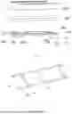
Referring to FIG. 1 and FIG. 2, the present embodiment provides a treadmill deck motor mounting structure, which is mounted on the side of a treadmill adjacent to a front roller 200 and is configured to provide a driving force to the front roller 200. The treadmill includes a support frame body 100. The support frame body 100 is a rectangular frame and includes two support tubes 110 arranged in parallel. A plurality of support bars 120 are arranged along a length direction of the support tubes 110, and two ends of each support bar 120 are fixedly connected to the support tubes 110 on corresponding sides, thereby enhancing the structural strength of the support frame body. A connecting portion 111 is provided on an upper surface of each support tube 110.
A front roller 200 is mounted at a front end of the support frame body 100. One side of the front roller 200 is connected to a motor 600 which provides a driving force. A rear roller 300, parallel to the front roller 200, is mounted at a rear end of the support frame body 100. A treadmill belt 400 is connected to the front roller 200 and the rear roller 300. As the front roller 200 and the rear roller 300 rotate, the treadmill belt 400 is driven in a unidirectional manner. The treadmill belt 400 is an elongated hollow annular structure, and a treadmill deck 500 is disposed inside the hollow annular structure. The treadmill belt 400 is wrapped around the support frame body 100 to form a moving contact surface on an upper side of the support frame body 100. An output shaft of the motor 600 is connected to the front roller 200 to drive the rotation of the front roller 200, so that the front roller 200 drives the treadmill belt 400 to move on the moving contact surface.
Specifically, the two support tubes 110 on both sides have different lengths. A front end surface of the support tube 110 on one side is spaced apart from the front roller 200, defining a space for accommodating a motor mounting housing 700. The motor mounting housing 700 is mounted in the space and welded and fixed to the support tube 110 on the side. This configuration not only enables a more compact overall structure and reduces the overall size, but also shortens a motion transmission distance and improves transmission efficiency.
The support tube 110 is a square hollow tube, which ensures strength while reducing the weight, thereby decreasing the overall weight of a machine. A protective cover 112 is connected to a rear end of each support tube 110. At least one cushion block 113 is provided on a lower side of each support tube 110 for anti-slip and sound insulation purposes. Preferably, the cushion block 113 is disposed near a rear portion of the support tube 110. The cushion block 113 has slight elasticity and may be made of a rubber, silicone, or PVC material to provide better shock absorption and cushioning performance. To further improve the friction resistance of the cushion block 113, micro-protrusion particles are formed on a bottom of the cushion block 113 to enhance a frictional force when in contact with the ground.
Embodiment 1
-
- Referring to FIG. 3a to FIG. 3f, the motor mounting housing 700 has an elongated mounting cavity 710, and a top of the elongated mounting cavity 710 is an opening structure for accommodating the motor 600 and a belt pulley 800 coaxially connected to the front roller 200. One end of the front roller 200 is connected to the motor mounting housing 700. The output shaft of the motor 600 is connected to the belt pulley 800 via a belt 810 to achieve power transmission. The motor 600 is characterized by a miniature size and can be flexibly disposed within the mounting cavity 710 of the motor mounting housing without requiring additional space for motor placement, effectively saving space.
To avoid interference between the front roller 200 and the motor mounting housing 700, a semi-circular recess with an upward opening is formed on a sidewall of the motor mounting housing 700 on the side adjacent to the front roller 200. The radius of the recess is greater than the radius of the front roller 200, allowing the front roller 200 to extend into the mounting cavity 710, such that the belt pulley 800 connected thereto is positioned within the mounting cavity 710. By providing the belt pulley 800 and the motor 600 within the mounting cavity 710, the integrity of a transmission structure is improved, and installation and subsequent maintenance are facilitated.
In the embodiment of the present disclosure, a first mounting opening 510 for accommodating the motor 600 is formed on the side of the treadmill deck 500 adjacent to the motor 600; when installed, the motor 600 is embedded in the first mounting opening 510, and an outer surface of the motor mounting housing 700 and an outer surface of the support tube 110 on the same side lie in the same plane, thereby reducing the distance in a width direction and further decreasing the overall size of the machine.
The motor mounting housing 700 is provided with lug plates 720 that extend horizontally toward the treadmill deck 500. The lug plates 720 are fixedly connected to the treadmill deck 500 via screws, or by welding or riveting.
Embodiment 2
-
- Referring to FIG. 4a to FIG. 4g, the structure and installation position of the motor mounting housing 700 are consistent with those in Embodiment 1. The volume of the mounting cavity 710 is greater than the volume of the motor 600, so that the entire motor 600 is accommodated within the mounting cavity 710. The mounting cavity 710 has a first sidewall 711 and a second sidewall 712 arranged parallel to the first sidewall 711, and the first sidewall 711 is arranged adjacent to the treadmill deck 500. The output shaft of the motor 600 passes through the second sidewall 712 of the motor mounting housing 700. A belt pulley 800 is coaxially connected to the front roller 200, and an end of the front roller 200 passes through the second sidewall 712 of the motor mounting housing. The belt pulley 800 disposed within the mounting cavity 710. The belt pulley 800 is connected to the output shaft of the motor 600 via a belt 810. An arc-shaped recess with an upward opening is formed on an upper surface of the first sidewall 711 of the motor mounting housing, facilitating the entry of the front roller 200 into the mounting cavity 710.
A first slot 731 corresponding to the position of the belt pulley 800 and a second slot 732 corresponding to the position of the motor 600 are formed in a bottom 730 of the motor mounting housing 700, which facilitates heat dissipation during operation of the belt pulley and the motor and avoids heat accumulation that could affect performance, thereby extending the service life.
A first mounting opening 510 is formed on an end surface of the treadmill deck 500 on the side adjacent to the motor mounting housing 700 to reserve a space for the installation of the motor mounting housing 700. The first mounting opening 510 is formed on the end surface, facilitating control of the size of the first mounting opening 510 to avoid excessive cutting, thereby reducing waste of plate materials.
A horizontal bend 7111 is formed at a top end of the first sidewall 711 of the motor mounting housing, and the horizontal bend 7111 is fitted against a bottom surface of the treadmill deck 500 and fixed to the treadmill deck 500 via screws. Since the motor mounting housing 700 has a relatively large width and is fixedly connected only to an end surface of the shorter support tube 110, the stability thereof may be adversely affected. In particular, vibration may occur during the operation of the motor 600. Therefore, an additional connection point is provided to improve the mounting stability of the motor mounting housing 700.
Embodiment 3
-
- Referring to FIG. 5a to FIG. 5f, the structure and installation position of the motor mounting housing 700 are consistent with those in Embodiment 2. A belt pulley 800 is located on an outer side of the first sidewall 711 facing the treadmill deck 500, and one end of the front roller 200 is connected to the first sidewall 711 of the motor mounting housing. The belt pulley 800 is mounted on an outer periphery of the front roller 200, and then the motor 600 and the belt pulley 800 are connected via a belt 810. This configuration facilitates the separate installation of the components and then the connection, thereby reducing the mounting difficulty of the belt pulley 800. Additionally, the belt pulley 800 is located outside the mounting cavity 710, which facilitates the adjustment of the spacing between the belt pulley 800 and the mounting cavity 710, thereby reducing the likelihood of interference. The motor 600 is characterized by a miniature size and can be flexibly disposed within the mounting cavity 710 of the motor mounting housing without requiring additional space for motor placement, effectively saving space.
Furthermore, the second sidewall 712 of the motor mounting housing is a detachable welded component. After the motor 600 is installed, the second sidewall 712 is welded and fixed to a corresponding peripheral wall of the motor mounting housing. This configuration facilitates the installation of the motor 600 and facilitates the adjustment of the installation position of the motor 600 as there is no obstruction of the second sidewall 712. During the installation process, workers can change the operation angle, reducing the mounting difficulty of the motor 600 and improving the mounting efficiency.
An arc-shaped recess with an upward opening is formed on an upper surface of the first sidewall 711 of the motor mounting housing. An outer peripheral edge of the motor 600 on the side adjacent to the output shaft is embedded in the arc-shaped recess, defining a mounting space of the motor 600. After the motor 600 is started, this configuration helps to reduce self-induced vibration and lowers the probability of noise generation.
According to the embodiment of the present disclosure, the treadmill deck motor mounting structure also comprises a controller 900. The controller 900 is designed in a right-angle shape. A horizontal section is parallel to the treadmill deck 500, and a clamping groove 910 is integrally formed on a vertical section, which improves the fixing accuracy of the controller 900 and the support tube 110.
Two first mounting openings 510 symmetrically arranged are formed on an end surface of the treadmill deck 500 adjacent to the motor 600, i.e., an outer contour line of the treadmill deck 500 is in an inverted-T shape, and the two first mounting openings 510 are arranged in left-right symmetry with respect to a center line of the treadmill deck 500 in a length direction, where “left” and “right” are defined based on the user-facing direction. One of the first mounting openings 510 is configured to accommodate the controller 900, and the other first mounting opening 510 can enlarge the mounting space for the belt 810 and the output shaft of the motor 600, thereby improving installation convenience. The first mounting openings 510 are formed on the end surface, facilitating control of the size of the first mounting openings 510 to avoid excessive cutting, thereby reducing waste of plate materials.
Embodiment 4
-
- Referring to FIG. 6a to FIG. 6g, the structure of the motor mounting housing 700 is consistent with that in Embodiment 2. A motor 600 and a dual-pulley transmission structure connected thereto are mounted in the mounting cavity 710. The dual-pulley transmission structure is connected to the front roller 200 to achieve motion transmission. By providing the dual-pulley transmission structure, the power output from the motor 600 is gradually transmitted to the front roller 200, thereby improving the transmission stability. The output shaft of the motor 600 is located inside the mounting cavity 710 and on the side away from the treadmill deck 500.
The dual-pulley transmission structure includes a pulley set 1000 connected to the motor 600 via a pulley set belt 1100, and a belt pulley 800 coaxially connected to the front roller 200. The pulley set 1000 and the belt pulley 800 are connected via a belt 810. A rotating shaft of the belt pulley 800 is connected to the motor mounting housing 700. The pulley set 1000 includes a driving pulley A and a driven pulley B coaxially arranged, where the diameter of the driving pulley A is greater than that of the driven pulley B. The output shaft of the motor 600 is connected to the driving pulley A via the pulley set belt 1100, and the driven pulley B is connected to the belt pulley 800 via the belt 810 to achieve transmission.
A first opening 520 and a second opening 530 are formed at an end surface of the treadmill deck 500 on the side adjacent to the motor mounting housing 700, forming a step shape. A motor body of the motor 600 is embedded in the first opening 520, and an input shaft is embedded in the mounting cavity 710 of the motor mounting housing. The second opening 530 serves as a reserved space for the installation of the motor mounting housing 700, allowing an outer edge of the motor mounting housing 700 and an outer edge of the treadmill deck 500 to lie in the same plane, thereby not only saving the mounting space, but also controlling the overall size, thereby reducing transportation costs.
Embodiment 5
-
- Referring to FIG. 7 a to FIG. 7 g, based on Embodiment 4, the motor 600 and the dual-pulley transmission structure are entirely mounted inside the motor mounting housing 700. An elongated second mounting opening 540 is formed on an end surface of the treadmill deck 500 on the side adjacent to the motor mounting housing 700. The second mounting opening 540 is configured to accommodate the motor mounting housing 700, eliminating the need to form a plurality of openings for accommodating the individual components and thereby improving processing efficiency. The length of the second mounting opening 540 matches that of the motor mounting housing 700, providing a reserved space for the installation of the motor mounting housing 700.
The above description is merely a description of the preferred embodiments of the present disclosure, and does not limit the scope of the present disclosure. Any changes or modifications made by those of ordinary skill in the field of the present disclosure based on the above-disclosed content shall fall within the scope of protection of the claims.
Claims
1. A treadmill deck motor mounting structure, comprising:
a support frame body, comprising two support tubes arranged in parallel and having different lengths, wherein end surfaces on one side of the two support tubes lie in the same plane, and a spacing between an end surface of the shorter support tube on the other side and the longer support tube defines an accommodating space for accommodating a motor mounting structure body;
the motor mounting structure body, disposed in the accommodating space, wherein a motor serving as a power source is mounted in the motor mounting structure body;
a front roller, disposed at a front end of the support frame body, wherein one end of the front roller is connected to the motor mounting structure body, and a belt pulley is disposed on an outer periphery of the end and connected to an output shaft of the motor via a belt;
a rear roller, arranged parallel to the front roller and disposed at a rear end of the support frame body;
a treadmill belt, connected to the front roller and the rear roller, wrapped around the support frame body to form a moving contact surface on an upper side of the support frame body, and driven by the rotation of the front and rear rollers in a unidirectional manner; and
a treadmill deck, mounted on a top of the support frame body and located within a hollow annular structure of the treadmill belt, wherein a recessed space is formed at the end of the treadmill deck adjacent to the motor mounting structure body and used for accommodating the motor mounting structure body, such that an opposing outer end surface of the motor mounting structure body and an opposing outer end surface of the support frame body lie in the same plane.
2. The treadmill deck motor mounting structure according to claim 1, wherein the motor mounting structure body comprises a motor mounting housing fixedly connected to a bottom surface of the treadmill deck, the motor mounting housing having a mounting cavity.
3. The treadmill deck motor mounting structure according to claim 2, wherein a first mounting opening for accommodating the motor is formed on the side of the treadmill deck adjacent to the motor; when installed, the motor is embedded in the first mounting opening, and an outer surface of the motor mounting housing and an outer surface of the support tube on the same side lie in the same plane.
4. The treadmill deck motor mounting structure according to claim 3, wherein the mounting cavity has a first sidewall and a second sidewall disposed parallel to the first sidewall, and the first sidewall is adjacent to the treadmill deck; the output shaft of the motor passes through the second sidewall of the motor mounting housing; and an end of the front roller passes through the second sidewall of the motor mounting housing, and the belt pulley is disposed in the mounting cavity.
5. The treadmill deck motor mounting structure according to claim 4, wherein a first slot corresponding to the position of the belt pulley and a second slot corresponding to the position of the motor are formed in a bottom of the motor mounting housing, which facilitates heat dissipation during operation of the belt pulley and the motor.
6. The treadmill deck motor mounting structure according to claim 3, wherein the mounting cavity has a first sidewall and a second sidewall which is detachably fixed and arranged parallel to the first sidewall, and the first sidewall is adjacent to the treadmill deck; and one end of the front roller is connected to the first sidewall of the motor mounting housing, and the belt pulley is located outside the mounting cavity, which facilitates adjustment of a distance between the belt pulley and the mounting cavity.
7. The treadmill deck motor mounting structure according to claim 6, further comprising a controller, wherein the controller is in a right-angle shape, a horizontal section is parallel to the treadmill deck, and a clamping groove is integrally formed on a vertical section, which improves the fixing accuracy of the controller and the support tube.
8. The treadmill deck motor mounting structure according to claim 3, wherein the motor and a dual-pulley transmission structure connected to the motor are mounted in the mounting cavity, and the dual-pulley transmission structure is connected to the front roller to achieve motion transmission.
9. The treadmill deck motor mounting structure according to claim 8, wherein the dual-pulley transmission structure comprises a pulley set connected to the motor through a pulley set belt and a belt pulley coaxially connected to the front roller, and the pulley set is connected to the belt pulley via a belt; the pulley set has a driving pulley A and a driven pulley B arranged coaxially; the driving pulley A has a larger diameter than the driven pulley B; and the output shaft of the motor is connected to the driving pulley A via the pulley set belt, and the driven pulley B is connected to the belt pulley via a belt.
10. A treadmill, comprising the treadmill deck motor mounting structure according to claim 1.
11. The treadmill of claim 10, wherein the motor mounting structure body comprises a motor mounting housing fixedly connected to a bottom surface of the treadmill deck, the motor mounting housing having a mounting cavity.
12. The treadmill of claim 11, wherein a first mounting opening for accommodating the motor is formed on the side of the treadmill deck adjacent to the motor; when installed, the motor is embedded in the first mounting opening, and an outer surface of the motor mounting housing and an outer surface of the support tube on the same side lie in the same plane.
13. The treadmill of claim 12, wherein the mounting cavity has a first sidewall and a second sidewall disposed parallel to the first sidewall, and the first sidewall is adjacent to the treadmill deck; the output shaft of the motor passes through the second sidewall of the motor mounting housing; and an end of the front roller passes through the second sidewall of the motor mounting housing, and the belt pulley is disposed in the mounting cavity.
14. The treadmill of claim 13, wherein a first slot corresponding to the position of the belt pulley and a second slot corresponding to the position of the motor are formed in a bottom of the motor mounting housing, which facilitates heat dissipation during operation of the belt pulley and the motor.
15. The treadmill of claim 12, wherein the mounting cavity has a first sidewall and a second sidewall which is detachably fixed and arranged parallel to the first sidewall, and the first sidewall is adjacent to the treadmill deck; and one end of the front roller is connected to the first sidewall of the motor mounting housing, and the belt pulley is located outside the mounting cavity, which facilitates adjustment of a distance between the belt pulley and the mounting cavity.
16. The treadmill of claim 15, further comprising a controller, wherein the controller is in a right-angle shape, a horizontal section is parallel to the treadmill deck, and a clamping groove is integrally formed on a vertical section, which improves the fixing accuracy of the controller and the support tube.
17. The treadmill of claim 12, wherein the motor and a dual-pulley transmission structure connected to the motor are mounted in the mounting cavity, and the dual-pulley transmission structure is connected to the front roller to achieve motion transmission.
18. The treadmill of claim 17, wherein the dual-pulley transmission structure comprises a pulley set connected to the motor through a pulley set belt and a belt pulley coaxially connected to the front roller, and the pulley set is connected to the belt pulley via a belt; the pulley set has a driving pulley A and a driven pulley B arranged coaxially; the driving pulley A has a larger diameter than the driven pulley B; and the output shaft of the motor is connected to the driving pulley A via the pulley set belt, and the driven pulley B is connected to the belt pulley via a belt.
Images & Drawings included:


Sources:
- United States Patent and Trademark Office - verify current appl. status at the USPTO↗
Recent applications in this class:
- » 20260166372 2026-06-18
ULTRA-THIN OMNIDIRECTIONAL TREADMILL APPARATUS - » 20260021343 2026-01-22
DRIVING DEVICE OF TREADMILL, AND TREADMILL - » 20260014415 2026-01-15
MULTIFUNCTIONAL SLIDING STORAGE TREADMILL - » 20260007925 2026-01-08
SMART TREADMILL FOR PERFORMING CARDIOVASCULAR REHABILITATION - » 20260007924 2026-01-08
DOUBLE-SIDED TREADMILL - » 20250288862 2025-09-18
TREADMILL - » 20250288861 2025-09-18
TREADMILL WITH UPWARD/DOWNWARD INCLINATION ANGLE ADJUSTMENT STRUCTURE - » 20250229124 2025-07-17
TREADMILL - » 20250205546 2025-06-26
TREADMILL ARRANGEMENT WITH MOTION-ADAPTIVE VIRTUAL RUNNING ENVIRONMENT - » 20250010129 2025-01-09
ELECTRIC TREADMILL