FLYING DISC TARGET UPPER ASSEMBLY ATTENUATION SYSTEM
US20260183641A1
2026-07-02
19/007,518
2025-01-01
Smart Summary: A new system for disc golf targets helps control how a flying disc behaves when it hits the target. It includes a special upper structure that can tilt and resist twisting when a disc lands in the target area. This tilting action softens the impact, guiding the disc downward into the basket. The twist resistance helps to keep the disc from bouncing out, ensuring it stays in the target. Overall, this design improves the chances of successfully capturing the disc. 🚀 TL;DR
Abstract:
Disclosed embodiments provide a disc golf target with an impact attenuation system governing direction and speed of a flying disc. The disc golf target includes an upper assembly structure, groups of upper assembly members, and/or individual upper assembly members that can provide tilt with twist resistance upon receiving a disc within the ‘target zone’. The tilt softens the collision and effectively redirects the disc downward toward the basket while twist resistance reduces kinetic energy and the tendency for a disc to escape entanglement, resulting in capture.
Applicant:
Interested in similar patents?
Get notified when new applications in this technology area are published.
Classification:
A63B67/06 » CPC main
Sporting games or accessories therefor, not provided for in groups - Ring or disc tossing games, e.g. quoits; Throwing or tossing games, e.g. using balls; Games for manually rolling balls, e.g. marbles
A63B63/08 » CPC further
Targets or goals for ball games with horizontal opening for ball, e.g. for basketball
Description
FIELD
The present invention relates generally to sports equipment, and more particularly to a flying disc target upper assembly attenuation system.
BACKGROUND
Disc golf is a growing recreational activity that combines elements of traditional golf with the enjoyment of throwing a flying disc. Disc golf is an accessible and rewarding sport that offers fun, challenges, and physical activity benefits for players of all ages and skill levels. Disc golf can provide social enjoyment. Played in groups, disc golf fosters camaraderie and friendly competition among friends and family. Moreover, disc golf is a great way to meet new people through local leagues and tournaments. Courses are often set in beautiful parks, forests, or open fields, allowing players to connect with nature. The variety in course layouts serves to keep the game interesting, with different terrains and obstacles. Another advantage of disc golf is that minimal equipment is needed, making it easy for beginners to start. Furthermore, disc golf is suitable for all ages and abilities, with courses often designed to cater to various skill levels. There is a creative aspect to the sport, in that each throw offers an opportunity for creativity, as players experiment with angles, throwing styles, and disc choices.
Although it is easy to get started playing disc golf, to become proficient can take skill and mental discipline. Mastering different types of throws (e.g., backhand, forehand, and overhead) and understanding how discs fly requires practice and patience. Additionally, players must learn to adjust their throws for wind conditions, slopes, and other environmental factors. Similar to “regular” golf, course layouts demand strategic decisions on each hole, such as choosing the right disc or navigating obstacles like trees and water hazards. Progressing in disc golf involves overcoming challenges such as achieving longer throws, improving accuracy, and handling difficult terrain. For those who participate in tournaments, the competitive aspect adds an extra layer of excitement and motivation.
In addition to the social and mental benefits, disc golf also provides physical benefits. A round of disc golf can involve walking several miles, often across varied terrain, which provides cardiovascular benefits. This makes disc golf a low-impact form of exercise suitable for individuals of all fitness levels. Throwing discs engages muscles in the arms, shoulders, core, and legs, helping to build strength. Moreover, the twisting and turning motions improve flexibility and range of motion. Additionally, navigating uneven ground and maintaining balance during throws enhance overall coordination and stability. Furthermore, spending time outdoors reduces stress and boosts mood, while the focus required for each throw provides a mental workout. The mix of exercise and fun makes disc golf an excellent activity for mental and physical well-being.
SUMMARY
In one aspect of disclosed embodiments, there is provided a flying disc target upper assembly attenuation system, comprising: a base; an elongated member, wherein the elongated member is supported from the base in a vertical orientation; a basket suspended from the elongated member above the base; an upper assembly, the upper assembly mounted on the elongated member above the basket; at least one disc attenuator originating from the upper assembly; and wherein an allocation of the upper assembly is configured to be tiltable with respect to the elongated member, thereby directing an incident disc into the basket; and wherein further the allocation of the upper assembly configured to be tiltable employs twist resistance to suppress kinetic energy, thereby directing the disc from escape.
In another aspect of disclosed embodiments, there is provided a flying disc target upper assembly attenuation system, comprising: a base; an elongated member, wherein the elongated member is supported from the base in a vertical orientation; a basket suspended from the elongated member above the base; an upper assembly, the upper assembly mounted on the elongated member above the basket; a plurality of disc attenuators radially originating from the upper assembly; and wherein an allocation of the upper assembly is configured to be tiltable with respect to the elongated member, thereby directing an incident disc into the basket; and wherein further the allocation of the upper assembly configured to be tiltable employs twist resistance to suppress kinetic energy, thereby directing the disc from escape.
BRIEF DESCRIPTION OF THE DRAWINGS
The structure, operation, and advantages of the present invention will become further apparent upon consideration of the following description taken in conjunction with the accompanying figures (FIGs). The figures are intended to be illustrative, not limiting.
Certain elements in some of the figures may be omitted, or illustrated not-to-scale, for illustrative clarity. The cross-sectional views may be in the form of “slices”, or “near-sighted” cross-sectional views, omitting certain background lines which would otherwise be visible in a “true” cross-sectional view, for illustrative clarity.
Often, similar elements may be referred to by similar numbers in various figures (FIGs) of the drawing, in which case typically the last two significant digits may be the same, the most significant digit being the number of the drawing figure (FIG). Furthermore, for clarity, some reference numbers may be omitted in certain drawings.
FIG. 1 shows a flying disc target upper assembly attenuation system, in accordance with disclosed embodiments.
FIG. 2A shows details of an embodiment of a flying disc target upper assembly attenuation system using a loop support, bi-attach bracket in an independent configuration, in accordance with disclosed embodiments.
FIG. 2B shows details of an embodiment of a flying disc target upper assembly attenuation system using a straddle support, bi-attach bracket in a network configuration, in accordance with disclosed embodiments.
FIG. 3 shows details of an embodiment of a flying disc target upper assembly attenuation system using a loop support, tri-attach bracket in an independent configuration, in accordance with disclosed embodiments.
FIG. 4 shows details of an embodiment of a flying disc target upper assembly attenuation system using a loop support, tri-attach bracket in a network configuration, in accordance with disclosed embodiments.
FIG. 5 shows details of an open loop support, open bi-attach, angled bracket, in accordance with disclosed embodiments.
FIG. 6 shows details of a loop support, bi-attach bracket with angled loops, in accordance with disclosed embodiments.
FIG. 7 shows details of an embodiment of a flying disc target upper assembly attenuation system using a sleeve support, bi-attach bracket, in accordance with disclosed embodiments.
FIG. 8 shows details of a loop support, quad-attach bracket, in accordance with disclosed embodiments.
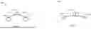
FIG. 9A shows details of upper assembly operation at rest.
FIG. 9B shows details of upper assembly operation with an incoming disc.
FIG. 10A shows details of a central hub 1040 upper assembly in accordance with additional embodiments.
FIG. 10B shows details of a central hub 1040 upper assembly of FIG. 10A mount on the elongated member column 1002.
FIG. 10C shows details of chain attachment of the upper assembly of FIG. 10A.
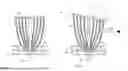
FIG. 11A shows a top-down view of a portion of the upper assembly prior to contact with an incoming disc.
FIG. 11B shows a top-down view of a portion of the upper assembly after contact with an incoming disc.
FIG. 12A shows details of upper assembly mount of a frictional flat surface central hub in accordance with disclosed embodiments.
FIG. 12B shows details of upper assembly mount of a textured surface central hub in accordance with disclosed embodiments.
FIG. 12C shows details of upper assembly mount of a flexible tabbed central hub in accordance with additional disclosed embodiments.
DETAILED DESCRIPTION
The disc golf target, which can include a pole with a basket and chains, is the centerpiece of disc golf gameplay. An effective target is crucial to the sport as it directly influences the precision, satisfaction, and pace of play. The design of the target, especially the impact attenuation system, plays a pivotal role in ensuring fair and enjoyable gameplay. Disclosed embodiments provide an improved attenuation system that redirects discs downward and reduces the forceful rebound of discs upon impact, increasing the probability that the discs stay within the basket area rather than bouncing out, followed with prompt return to stable resting position. By securely capturing correctly thrown discs, players experience greater satisfaction and fewer disappointments, especially for beginners seeking positive reinforcement or competitive professionals on challenging and financially consequential shots. Disclosed embodiments provide a system that diverts discs downward upon impact, and ensures they settle into the basket efficiently, reducing the chance of ricochets or deflections. Thus, players are rewarded more consistently for well-aimed throws, maintaining fairness and accuracy in gameplay. Another advantage of disclosed embodiments can include reduced time per hole. Reliable disc capture eliminates the need to retrieve discs that bounce out or skip past the target, allowing players to move quickly to the next hole. This can also streamline tournament play. In competitive settings, faster play ensures smoother scheduling and better flow of games.
Disclosed embodiments can provide increased enjoyment when playing disc golf. A target that reliably captures successful throws boosts player confidence and enhances the overall experience. Moreover, newcomers to the sport are less discouraged by missed captures due to target design flaws, fostering growth in the disc golf community. Additionally, disclosed embodiments can better handle discs of varying weights, speeds, and angles, ensuring consistency across diverse courses and weather conditions.
Disclosed embodiments achieve the aforementioned benefits by providing an entire upper assembly structure, groups of upper assembly members, and/or individual upper assembly members that can tilt with twist resistance upon impact from a disc within the ‘target zone’. This tilt and twist resistance softens the collision, reducing the tendency for a disc to bounce away and effectively redirects the disc downward toward the basket. The attenuation movements from the tilting upper assembly structure of disclosed embodiments can favorably influence the overall capture reaction rate. The attenuation system of disclosed embodiments can provide mechanics that are more deliberate, uniform and consistent compared to the jerked action and random ‘chain splash’ from fixed upper assembly targets, and compliments the ability to capture more accurately thrown discs. Additionally, as the upper assembly structure tilts downwardly during impact of a disc, the opposite side of the target upper assembly structure may be raised, resulting in a backside chain or curtain of chains that become relatively tauter to keep rebounds within the basket's perimeter. After the disc lands in the basket the tilted upper assembly structure may promptly return to proper resting position. Moreover, manufacturing and distribution costs may decrease with disclosed embodiments, as other upper assembly structure elements such as radial support ribs or extra chain may be reduced without sacrificing performance.
The descriptions throughout this disclosure contain simplifications, generalizations and omissions of detail and is not intended as a comprehensive description of the claimed subject matter but, rather, is intended to provide a brief overview of some of the functionality associated therewith. Other systems, methods, functionality, features, and advantages of the claimed subject matter will be or will become apparent to one with skill in the art upon examination of the figures and the remaining detailed written description. The above as well as additional objectives, features, and advantages of the present disclosure will become apparent in the following detailed description.
In the following description, specific example embodiments in which the disclosure may be practiced are described in sufficient detail to enable those skilled in the art to practice the disclosed embodiments. For example, specific details such as specific method orders, structures, elements, and connections have been presented herein. However, it is to be understood that the specific details presented need not be utilized to practice embodiments of the present disclosure. It is also to be understood that other embodiments may be utilized and that logical, architectural, programmatic, mechanical, electrical and other changes may be made without departing from the general scope of the disclosure. The following detailed description is, therefore, not to be taken in a limiting sense, and the scope of the present disclosure is defined by the appended claims and equivalents thereof.
References within the specification to “one embodiment,” “an embodiment,” “embodiments”, or “one or more embodiments” are intended to indicate that a particular feature, structure, or characteristic described in connection with the embodiment is included in at least one implementation (embodiment) of the present disclosure. The appearance of such phrases in various places within the specification are not necessarily all referring to the same embodiment, nor are separate or alternative embodiments mutually exclusive of other embodiments. Further, various features are described which may be exhibited by some embodiments and not by others. Similarly, various aspects are described which may be aspects for some embodiments but not for other embodiments.
The terminology used herein is for the purpose of describing particular embodiments only and is not intended to be limiting of the disclosure. As used herein, the singular forms “a”, “an”, and “the” are intended to include the plural forms as well, unless the context clearly indicates otherwise. It will be further understood that the terms “comprises” and/or “comprising,” when used in this specification, specify the presence of stated features, integers, steps, operations, elements, and/or components, but do not preclude the presence or addition of one or more other features, integers, steps, operations, elements, components, and/or groups thereof. Moreover, the use of the terms first, second, etc. do not denote any order or importance, but rather the terms first, second, etc. are used to distinguish one element (e.g., a person or a device) from another.
It is understood that the use of specific component, device and/or parameter names and/or corresponding acronyms thereof, are for example only and not meant to imply any limitations on the described embodiments. The embodiments may thus be described with different nomenclature and/or terminology utilized to describe the components, devices, parameters, methods and/or functions herein, without limitation. References to any specific protocol or proprietary name in describing one or more elements, features or concepts of the embodiments are provided solely as examples of one implementation, and such references do not limit the extension of the claimed embodiments to embodiments in which different element, feature, protocol, or concept names are utilized. Thus, each term utilized herein is to be provided its broadest interpretation given the context in which that term is utilized.
Within the descriptions of the different views of the figures, the use of the same reference numerals and/or symbols in different drawings indicates similar or identical items, and similar elements can be provided similar names and reference numerals throughout the figure(s). The specific identifiers/names and reference numerals assigned to the elements are provided solely to aid in the description and are not meant to imply any limitations (structural or functional or otherwise) on the described embodiments.
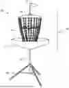
FIG. 1 shows a flying disc target upper assembly attenuation system, in accordance with disclosed embodiments. Flying disc target upper assembly attenuation system 100 comprises a base 104. The base 104 provides the foundational support for the target. In one or more portable embodiments, the base can include multiple legs, where the legs are arranged in a tripod, quadruped, or pentapod design, to ensure stability on uneven terrain. Or the portable base can be a circular perimeter foundation to provide efficient stability on even surfaces. In one or more in-ground embodiments, the base may be comprised of compacted ground, gravel and/or cement. Extending from the base is elongated member column 102, configured in a vertical orientation, and which serves as the central spine of the target. In one or more embodiments, the elongated member column 102 is comprised of a durable material such as steel or aluminum to withstand outdoor conditions and repeated impacts. In other embodiments the elongated member column 102 may be comprised of economically favorable materials such as plastic, wood, or composite.
Suspended from elongated member column 102 above base 104 is basket 110. The basket 110 is the primary structure for catching the disc. In one or more embodiments, the basket 110 comprises a metal cage structure. In other embodiments the basket 110 is comprised of a collapsible metal infrastructure surrounded by a mesh cover with an inverted open umbrella shape to securely cradle a captured disc. Upper assembly 108 is disposed above the basket 110. In one or more embodiments, the upper assembly 108 is comprised of a metal support structure. In other embodiments the upper assembly 108 is comprised of an open umbrella shaped mesh cover over a collapsible metal infrastructure with a central tiltable hub. The upper assembly serves to provide a framework from which attenuator members originate, such as chain 109. Other embodiments may use rope, tubing, netting and/or cable, instead of, or in addition to chain. A flag 112 may be affixed to the top of the upper assembly 108 to enable improved visibility of the disc target and to observe wind conditions.
In one or more embodiments, at least one disc attenuator comprises chain. In one or more embodiments, at least one disc attenuator comprises cable. In one or more embodiments, at least one disc attenuator comprises rope. In one or more embodiments, at least one disc attenuator comprises tubing. In one or more embodiments, at least one disc attenuator comprises netting. Upper section 126 comprises the basket 110, attenuator members (chain 109), and upper assembly 108. In one or more embodiments upper assembly 108 includes a central hub.
FIG. 2A shows details of an embodiment of a flying disc target upper assembly attenuation system using a loop support, bi-attach bracket in an independent configuration, in accordance with disclosed embodiments. A plurality of brackets, indicated generally as 207 are suspended from an upper assembly ring 205 that is supported from elongated member column 202. Chain, indicated generally as 209, originates from loops on the distal ends of each bracket. The brackets are moveably attached to upper assembly ring 205, such that when an incoming disc 220 impacts the chains, moving in the direction indicated by arrow 221, the disc 220 is then directed downward towards the basket (110 of FIG. 1), as indicated by arrow 222. In one or more embodiments, at least one disc attenuator originates from the upper assembly via a tiltable bracket, wherein the tiltable bracket is configured and disposed to tilt with respect to the elongated member column 202. In one or more embodiments, the tiltable bracket comprises a bi-attach bracket.
FIG. 2B shows details of an embodiment of a flying disc target upper assembly attenuation system using a straddle support, bi-attach bracket in a networked bracket configuration, in accordance with disclosed embodiments. In one embodiment the upper assembly ring 225 includes a plurality of spokes, indicated generally as 226, that can terminate with loops 227 disposed at a distal end of each spoke. For each spoke, a bracket 207 can be suspended along the spoke including from a distal loop 227. A bi-attach bracket includes two terminal loops, indicated generally as 215 and 217. Chain, shown generally as 209, can originate from each loop of the bi-attach bracket. A linking network chain, indicated generally as 234, is connected between adjacent bi-attach brackets. The linking network chains can serve to increase the stability of the attenuation structure and disperse disc impact energy from one attenuator strand throughout the system.
FIG. 3 shows details of an embodiment of a flying disc target upper assembly attenuation system using a loop support, tri-attach bracket in an independent configuration, in accordance with disclosed embodiments. A plurality of brackets, indicated generally as 307 are suspended from an upper assembly ring 305 that is mounted on the elongated member column 302. Chain, indicated generally as 309, originates from loops on the distal ends of each bracket. The brackets are moveably attached to the upper assembly ring 305, such that when an incoming disc 320 impacts the chains, moving in the direction indicated by arrow 321, the disc 320 is then directed downward towards the basket (110 of FIG. 1), as indicated by arrow 322. As compared with the bi-attach bracket shown in FIG. 2A, the tri-attach bracket can accommodate three chains per bracket, which increases the chain density per unit area. In one or more embodiments, the tiltable bracket comprises a tri-attach bracket.
FIG. 4 shows details of an embodiment of a flying disc target upper assembly attenuation system using a loop support, tri-attach bracket in a networked attenuator configuration, in accordance with disclosed embodiments. A plurality of brackets, indicated generally as 407 are suspended from an upper assembly ring 405 that is mounted on the elongated member column 402. Chain, indicated generally as 409, originates from loops on the distal ends of each bracket. The brackets are moveably attached to upper assembly ring 405, such that when an incoming disc 420 impacts the chains, moving in the direction indicated by arrow 421, the disc 420 is then directed downward towards the basket (110 of FIG. 1), as indicated by arrow 422. A linking network chain, indicated generally as 434, is connected between adjacent attenuators. The linking network chains can serve to increase the stability of the attenuation structure and disperse disc impact energy from one attenuator strand throughout the system.
FIG. 5 shows details of an open support loop, angled bi-attach bracket 500, in accordance with disclosed embodiments. Bracket 500 includes a first arm 514 having a first open loop 516 disposed at a distal end of first arm 514. Bracket 500 includes a second arm 518 having a second open loop 520 disposed at a distal end of second arm 518. Bracket 500 includes a supporting open loop 512 which is configured and disposed to engage with an upper assembly ring, such as shown at 205 in FIG. 2A or disposed at distal end of each spoke as shown at 227 in FIG. 2B.
FIG. 6 shows details of a loop support, bi-attach bracket with angled loops, in accordance with disclosed embodiments. Bracket 600 includes a first arm 614 having a first loop 616 disposed at an angle at a distal end of first arm 614. Bracket 500 includes a second arm 618 having a second loop 620 disposed at an angle at a distal end of second arm 618. Bracket 600 includes a supporting loop 612 which is configured and disposed to engage with an upper assembly ring, such as shown at 205 in FIG. 2A or disposed along spokes including at distal end of each spoke as shown at 227 in FIG. 2B.
FIG. 7 shows details of an embodiment of a flying disc target upper assembly attenuation system using a sleeve support, bi-attach bracket, in accordance with disclosed embodiments. Upper assembly ring 705 includes multiple radial spokes, indicated generally as 711. A sleeved bracket 707 is installed on radial spoke 711. The sleeved bracket 707 includes a bushing 717. The bushing 717 is disposed around radial spoke 711 of upper assembly ring 705. For each sleeved bracket, two arms, indicated generally as 722, each have a loop formed at a distal end, indicated generally as 724.
FIG. 8 shows details of a loop support, quad-attach bracket, in accordance with disclosed embodiments. Bracket 800 includes four arms. Arm 821 has loop 822 formed at a distal end. Arm 831 has loop 832 formed at a distal end. Arm 841 has loop 842 formed at a distal end. Arm 851 has loop 852 formed at a distal end. Bracket 800 includes a supporting loop 812 which is configured and disposed to engage with an upper assembly, such as shown at 205 in FIG. 2A or disposed along spokes including at distal end of each spoke as shown at 227 in FIG. 2B. As compared with the bi-attach bracket shown in FIG. 2A, the quad-attach bracket can accommodate four vertical chains per bracket, which increases the chain density per unit area. In one or more embodiments, the tiltable bracket comprises a quad-attach bracket.
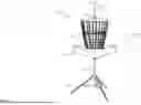
FIG. 9A shows details of upper assembly operation at rest. Upper section 900 of a flying disc target upper assembly attenuation system includes elongated member column 902, which serves as the central spine of the target. In one or more embodiments, the elongated member column 902 is comprised of a durable material such as steel or aluminum to withstand outdoor conditions and repeated impacts. Suspended from elongated member column 902 is basket 910. The basket 910 is the primary structure for catching the disc. In one or more embodiments, the basket 910 is comprised of a metal cage with a concave shape to cradle the disc securely. Upper assembly 908 is disposed above the basket 910. In one or more embodiments, the upper assembly 908 is tiltable and/or capable of twisting, where the twisting includes rotational motion, where the rotational motion is suppressed with resistance from frictional and/or mechanical influence. In one or more embodiments, the twisting resistance attenuates rotational kinetic energy below 90 degrees. The upper assembly 908 serves to provide a framework from which attenuator members originate, such as chain 909. Other embodiments may use rope, tubing, netting, and/or cable, instead of, or in addition to chain.
FIG. 9B shows details of an allocation of the upper assembly operation with an incoming disc 920, moving in the direction indicated by arrow 921. When the disc 920 impacts chain 909, it causes the allocation of the upper assembly 908 to deflect in relation to the elongated member column 902 by angle A (deflection angle A=total angle C minus resting angle B), as indicated in FIG. 9B, serving to aid in directing the disc 920 towards the basket 910. In embodiments, an allocation of the upper assembly is configured to be tiltable with respect to the elongated member column 902, thereby directing an incident flying disc into the basket. In embodiments, the allocation includes the upper assembly 908. In embodiments, the allocation of the upper assembly configured to be tiltable is resistant to twist, thereby directing an incident disc from escape with quick return to stable resting position. The tilt of the upper assembly increases the tautness of the backside chain 924, thereby serving to increase the probability of the disc 920 landing within the basket 910.
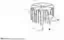
FIG. 10A shows details of an upper section in accordance with additional embodiments. Upper section 1000 of a flying disc target upper assembly attenuation system includes elongated member column 1002, which serves as the central spine of the target. In one or more embodiments, the elongated member column 1002 is comprised of a durable material such as steel or aluminum to withstand outdoor conditions and repeated impacts. Suspended from elongated member column 1002 is basket 1010. The basket 1010 is the primary structure for catching the disc. In one or more embodiments, the basket 1010 is comprised of a metal cage with a concave shape to cradle a captured disc securely. Upper assembly 1008 is disposed above the basket 1010. The upper assembly 1008 serves to provide a framework from which the attenuator members originate, such as chain 1009. Other embodiments may use tubing, netting, rope, and/or cable, instead of, or in addition to chain. The upper assembly 1008 includes a central hub 1040 for mounting on the elongated member column 1002. The elongated member column 1002 further includes chain attachment slot 1031 for securing chain to the elongated member column 1002.
FIG. 10B shows details of upper assembly support of FIG. 10A in the region indicated as 1034 in FIG. 10A. As can be seen in FIG. 10B, central hub 1040 is configured and disposed to frictionally engage with a flat top spindle 1042 that originates from the upper portion of elongated member column 1002.
FIG. 10C shows details of chain attachment of the upper assembly of FIG. 10A. In embodiments, the elongated member column 1002 may have a hollow interior, and links of chain 1009 may be inserted into the chain attachment slot 1031 to secure the chain to the elongated member column 1002. The chain attachment slot can include vertical slot 1035 and horizontal slot 1037 arranged in a ‘cross’ configuration. The attaching can include inserting links of chain through the slots, and then sliding the chain down below the horizontal slot to secure the chain by having a link of the chain disposed in the interior of the elongated member column 1002, held in place by the chain attachment slot 1031. In this embodiment the reduced twist resistance from spindle 1042 provides for catching the disc with less initial attenuation. This allows the disc to penetrate deeper into the target zone, which is then followed by an abrupt disruption from the attached upper assembly at attachment slot 1031 to capture the disc.
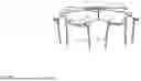
FIG. 11A shows a top-down view of a portion of the upper assembly prior to contact with an incoming disc. Disc 1110 is moving in the direction indicated by arrow 1111, towards upper assembly ring 1105. The upper assembly ring 1105 has a plurality of attenuators, such as chain (see 1009 of FIG. 10A) originating therefrom, (not shown in FIG. 11A). As shown in FIG. 11A, the disc 1110 is about to contact an attenuator connected to the upper assembly ring 1105 at point 1124.
FIG. 11B shows a top-down view of a portion of the upper assembly after contact with an incoming disc. Disc 1110 causes the upper assembly ring 1105 to move in the direction indicated by arrow 1141, causing a twisting motion. In one embodiment the connection of chain from the upper assembly to the elongated member column 1002 as shown in FIG. 10C serves as absolute resistance to prevent free rotation of the upper assembly ring 1105. In another embodiment FIG. 12A relative frictional resistance is employed with flat mated surfaces of elongated member column 1242 and hub 1204 to suppress rotation. Thus, the upper assembly ring 1105 can twist, but does not swivel (i.e., does not roll, spin or rotate freely). In this way, disclosed embodiments provide improved absorption of kinetic energy from the disc 1110 to increase the probability of the disc 1110 landing in a basket (e.g., 1010 of FIG. 10A).
FIG. 12A shows details of upper assembly support from 108 of FIG. 1 in accordance with disclosed embodiments. Central hub 1204 engages with elongated member column 1242, similar to as shown with spindle in FIG. 10B. FIG. 12A indicates a cross-section of the central hub 1204. In the embodiment of FIG. 12A, the central hub 1204 rests on elongated member column 1242. Elongated member column 1242 may be similar to spindle 1042 shown in FIG. 10B. The embodiment shown in FIG. 12A creates significant relative resistance to twist with flat frictional surfaces where the top of the elongated member column 1242 meets the inside hub pocket of central hub 1204 eliminating free roll motion and quickly returning to a stable reset position for timely speed of play.
FIG. 12B shows details of upper assembly support using a textured top surface 1228 of elongated member column 1242 and a textured inside hub pocket 1226 of upper assembly central hub 1224 in accordance with disclosed embodiments. Central hub 1224 engages with elongated member column 1242, similar to as shown with spindle in FIG. 10B. FIG. 12B indicates a cross-section of the central hub 1224. In the embodiment of FIG. 12B, the central hub 1224 includes inside hub pocket 1226 which has a textured frictional surface, and engages with a second textured frictional surface 1228 disposed on an upper surface of elongated member column 1242. The embodiment shown in FIG. 12B provides additional relative twist resistance as compared with the embodiment shown in FIG. 12A, thereby further reducing the amount of twist (rotation) of the upper assembly when a disc impacts the target as illustrated in FIG. 11B.
FIG. 12C shows details of upper assembly support using a tabbed friction hub in accordance with additional disclosed embodiments. Central hub 1244 engages with elongated member column 1242, similar to as shown with spindle in FIG. 10B. FIG. 12C indicates a cross-section of the central hub 1244. In the embodiment of FIG. 12C, the central hub 1244 includes flexible tabs 1246 disposed within an interior of the central hub 1244, and engages with cap 1248 disposed on an upper surface of elongated member column 1242, where the cap 1248 includes flexible tabs that engage with the flexible tabs 1246 within the central hub 1244. The embodiment shown in FIG. 12C provides additional twist resistance to substantially suppress kinetic energy as compared with the embodiment shown in FIG. 12A, thereby further reducing the amount of twist (rotation) of the upper assembly when a disc impacts the target as illustrated in FIG. 11B.
As can now be appreciated, disclosed embodiments provide a disc target that includes an improved impact attenuation system that serves to absorb the impact of an incoming disc and angle it downward towards the basket. Thus, disclosed embodiments enable a user to get the most out of playing disc golf. By rewarding skill, enhancing enjoyment, and supporting fast gameplay, disclosed embodiments elevate the overall playing experience for casual players and competitors alike.
While the disclosure has been described with reference to example embodiments, it will be understood by those skilled in the art that various changes may be made and equivalents may be substituted for elements thereof without departing from the scope of the disclosure. In addition, many modifications may be made to adapt a particular system, device, or component thereof to the teachings of the disclosure without departing from the scope thereof. Therefore, it is intended that the disclosure not be limited to the particular embodiments disclosed for carrying out this disclosure, but that the disclosure will include all embodiments falling within the scope of the appended claims.
Claims
What is claimed is:1. A flying disc target upper assembly attenuation system, comprising:
a base;
an elongated member, wherein the elongated member is supported from the base in a vertical orientation;
a basket suspended from the elongated member above the base;
an upper assembly, the upper assembly suspended from the elongated member above the basket;
at least one disc attenuator suspended from the upper assembly; and
wherein an allocation of the upper assembly is configured to be tiltable with respect to the elongated member, thereby directing an incident disc into the basket; and
wherein further the allocation of the upper assembly configured to be tiltable employs twist resistance to prevent free swivel, thereby directing the disc from escape.
2. The system of claim 1, wherein at least one disc attenuator is suspended by the upper assembly via a tiltable bracket, wherein the tiltable bracket is configured and disposed to tilt with respect to the elongated member.
3. The system of claim 2, wherein the tiltable bracket comprises a bi-attach bracket.
4. The system of claim 2, wherein the tiltable bracket comprises a tri-attach bracket.
5. The system of claim 2, wherein the tiltable bracket comprises a quad-attach bracket.
6. The system of claim 1, wherein at least one disc attenuator comprises chain.
7. The system of claim 1, wherein at least one disc attenuator comprises cable.
8. The system of claim 1, wherein at least one disc attenuator comprises rope.
9. The system of claim 1, wherein at least one disc attenuator comprises tubing.
10. The system of claim 1, wherein at least one disc attenuator comprises netting.
11. A flying disc target upper assembly attenuation system, comprising:
a base;
an elongated member, wherein the elongated member is supported from the base in a vertical orientation;
a basket suspended from the elongated member above the base;
an upper assembly, the upper assembly suspended from the elongated member above the basket;
a plurality of disc attenuators radially suspended from the upper assembly; and
wherein an allocation of the upper assembly is configured to be tiltable with respect to the elongated member, thereby directing an incident disc into the basket; and
wherein further the allocation of the upper assembly configured to be tiltable employs twist resistance to prevent free swivel, thereby directing the disc from escape.
12. The system of claim 11, wherein at least one disc attenuator is suspended by the upper assembly via a tiltable bracket, wherein the tiltable bracket is configured and disposed to tilt with respect to the elongated member.
13. The system of claim 12, wherein the tiltable bracket comprises a bi-attach bracket.
14. The system of claim 12, wherein the tiltable bracket comprises a tri-attach bracket.
15. The system of claim 12, wherein a tiltable bracket comprises a quad-attach bracket.
16. The system of claim 11, wherein the plurality of disc attenuators comprises chain.
17. The system of claim 11, wherein the plurality of disc attenuators comprises rope.
18. The system of claim 11, wherein the plurality of disc attenuators comprises cable.
19. The system of claim 11, wherein the plurality of disc attenuators comprises tubing.
20. The system of claim 11, wherein the plurality of disc attenuators comprises netting.
Images & Drawings included:


Sources:
- United States Patent and Trademark Office - verify current appl. status at the USPTO↗
Recent applications in this class:
- » 20260158350 2026-06-11
DISC GOLF TARGET - » 20260137993 2026-05-21
MEMORY DEVICE FOR POOL GAME - » 20260108791 2026-04-23
Electronic Beanbag Toss Game Board with Automatic Scoring - » 20260097285 2026-04-09
MULTI-MODAL PROJECTILE GAME - » 20260097284 2026-04-09
ROTATABLE CORNHOLE - » 20260084028 2026-03-26
BEACH GAME AND RACK ASSEMBLIES - » 20260077254 2026-03-19
GAME APPARATUS AND METHOD - » 20260077253 2026-03-19
CORNHOLE GAME BOARD LAMP WITH INFRARED BEAM SENSING AND MEMORY FUNCTION - » 20260069948 2026-03-12
SYSTEM AND METHOD FOR ADHERENT GAMING EQUIPMENT AND GAMEPLAY - » 20260061280 2026-03-05
PROJECTILE PARTY GAME