Tank Car Underframe
US20260184352A1
2026-07-02
19/435,885
2025-12-30
Smart Summary: A railway tank car is designed to carry different types of goods. It has a tank made up of a shell and at least one end piece. A front sill pad is attached to the bottom of the tank shell at one end, helping to support the structure. A draft sill apparatus connects to the tank shell with the help of this front sill pad. Additionally, a body bolster is positioned across the draft sill to provide extra support for the tank. 🚀 TL;DR
Abstract:
According to particular embodiments, a railway tank car comprises a tank for transporting a commodity. The tank comprises a tank shell and at least one tank head. A front sill pad is welded to the underside of the tank shell. The front sill pad is located at a first end of the tank shell proximate the tank head and extending inboard longitudinally along the underside of the tank shell. A draft sill apparatus is coupled to the underside of the tank shell at least partially by the front sill pad. A body bolster extends transversely from and perpendicular to the draft sill apparatus for supporting the tank. The body bolster is coupled to the draft sill. The draft sill apparatus is welded to the front sill pad inboard of the body bolster and the inboard weld does not extend outboard of the body bolster.
Applicant:
Interested in similar patents?
Get notified when new applications in this technology area are published.
Classification:
B61D5/06 » CPC main
Tank wagons for carrying fluent materials Mounting of tanks; Integral bodies and frames
B61G9/00 » CPC further
Draw-gear
B61G9/00 » CPC further
Draught or buffing appliances peculiar to railway or tramway vehicles
Description
RELATED APPLICATION
This application claims priority to United States Provisional Application Serial No. 63/740,462, entitled “TANK CAR UNDERFRAME,” filed December 31, 2024.
TECHNICAL FIELD OF THE INVENTION
This disclosure generally relates to the field of railway tank cars, and more particularly, to an improved tank car underframe.
BACKGROUND
Railway tank cars may be used for carrying a variety of liquid, gaseous, and semi-liquid ladings. Such railway tank cars often include a horizontal, generally cylindrical tank. For center stub sill or draft sill type tank cars, the tank not only carries the lading, but is also used as a primary structural member by the railway car to carry longitudinal train loads. These cars typically have center stub sills or draft sills on each end of the car along with transverse bolster assemblies. The draft sills carry couplers at their outer ends and have truck assemblies pivotally connected thereto for rolling support of the ends of the tank car on the railway tracks. Saddle assemblies, or cradle assemblies, are typically provided at each end of the car. The saddle assembly usually comprises a circumferential saddle extending arcuately and transversely up from the bottom of the car and mating with a saddle pad, or bolster pad, that is attached to the tank. The saddle and saddle pad are typically of steel plate construction and conformed to fit onto the adjacent outer surface of the cylindrical tank. Each end of the tank typically also has a head pad, or front sill pad.
The pads, such as the front sill pad and saddle pad, serve to distribute the loads and stresses over a larger area and to help prevent rupture of the associated tank. The connection between the pads and the tank is designed to be stronger than between the pads and other components welded to the pad. This arrangement enhances safety by making rupture of the tank less likely.
A head brace is typically a U-shaped, wedge-like piece that is placed between the front sill pad and portions of the draft sill to facilitate attachment of the tank to the draft sill, and to reduce the geometric stress concentrations at the outboard attachment points.
SUMMARY OF THE INVENTION
The embodiments described herein include an improved tank car underframe. Particular embodiments eliminate the head brace and simplify the contour of the reinforcing pad. Particular embodiments include a tank car stub sill arrangement without a head brace where the tank rests on two vertical sill webs that are welded to reinforcing pads. The longitudinal attachment welds remain inboard of the body bolster webs. This reduces vertically oriented forces that can result in “Mode I” crack initiation and propagation. Vertical forces are carried by welds between the body bolster webs and the tank reinforcing pads and sill webs. The welds attaching the sill to the pads take mainly longitudinal loads.
According to particular embodiments, a railway tank car comprises a tank for transporting a commodity. The tank comprises a tank shell and at least one tank head. A front sill pad is welded to the underside of the tank shell. The front sill pad is located at a first end of the tank shell proximate the tank head and extending inboard longitudinally along the underside of the tank shell. A draft sill apparatus is coupled to the underside of the tank shell at least partially by the front sill pad. A body bolster extends transversely from and perpendicular to the draft sill apparatus for supporting the tank. The body bolster is coupled to the draft sill. The draft sill apparatus is welded to the front sill pad inboard of the body bolster and the inboard weld does not extend outboard of the body bolster.
Certain embodiments may provide one or more of the following advantages. For example, advantages of particular embodiments include: increased fatigue life and reduced maintenance; reduced inspection requirements; simplified manufacturing; potential cost and weight reduction; and/or simplified application of heater coils.
BRIEF DESCRIPTION OF THE DRAWINGS
A more complete and thorough understanding of the particular embodiments and advantages thereof may be acquired by referring to the following description taken in conjunction with the accompanying drawings, in which like reference numbers indicate like features, and wherein:
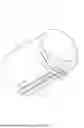
FIG. 1 is a schematic drawing illustrating a side view of a railway tank car;
FIG. 2 is a schematic drawing illustrating a side view of a railcar tank and draft sills;
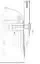
FIG. 3 is a schematic detailed elevational view of the connection between a railcar tank and a draft sill;
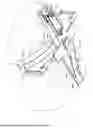
FIG. 4 is a schematic detailed perspective view of the connection between a railcar tank and a draft sill;
FIG. 5 is a schematic perspective view of a draft sill and body bolster;
FIG. 6 is a schematic perspective view of a tank with the draft sill and body bolster removed;
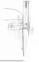
FIG. 7 is a schematic elevation view of an improved tank car underframe, according to particular embodiments;
FIG. 8 is a schematic perspective view of an improved tank car underframe, according to particular embodiments;
FIG. 9 is a schematic detailed view of a front sill pad and bolster web, according to particular embodiments;
FIG. 10 is a schematic end view of a body bolster, according to particular embodiments;
FIG. 11 is a schematic top view of a body bolster, according to particular embodiments;
FIG. 12 is a schematic front view of a body bolster and tank, according to particular embodiments;
FIG. 13 is a schematic side view of a body bolster, draft sill apparatus, and tank, according to particular embodiments;
FIG. 14A is an example of cross section A-A indicated in FIG. 10, according to particular embodiments;
FIG. 14B is another example of cross section A-A indicated in FIG. 10, according to particular embodiments;
FIG. 15A is an example of cross section B-B indicated in FIG. 11, according to particular embodiments;
FIG. 15B is another example of cross section B-B indicated in FIG. 11, according to particular embodiments;
FIG. 16 is an example of cross section C-C indicated in FIG. 12;
FIG. 17 is an example of cross section E-E indicated in FIG. 13;
FIG. 18 is an example of cross section F-F indicated in FIG. 13;
FIG. 19 is an example of cross section G-G indicated in FIG. 13;
FIG. 20 is an example of cross section K-K indicated in FIG. 13;
FIG. 21 is a schematic elevation view of an improved tank car underframe with additional bolsters, according to particular embodiments;
FIG. 22 is a schematic perspective view of an improved tank car underframe with additional bolsters, according to particular embodiments;
FIG. 23 is a schematic elevation view of an improved tank car underframe with an additional bolster and bolster pad, according to particular embodiments;
FIG. 24 is a schematic perspective view of an improved tank car underframe with an additional bolster and bolster pad, according to particular embodiments;
FIG. 25 is another schematic perspective view of an improved tank car underframe with an additional bolster and bolster pad, according to particular embodiments; and
FIG. 26 is another schematic perspective view of an improved tank car underframe with an additional bolster and bolster pad, according to particular embodiments.
DETAILED DESCRIPTION
Conventional designs for tank car stub sills employ a head brace connecting the draft sill to a reinforcing pad conforming to and attached to the tank head and shell, as described in the Background section above. The head brace is used because of the high susceptibility for fatigue cracks and/or fracture at the weld connection between the draft sill and the tank reinforcing pads. This design has drawbacks, including the following: (a) precise fit-up is difficult to achieve because the head and pad profiles can vary in shape and diameter; (b) the longitudinal position of the sill relative to the tank head also introduces fit-up variation; (c) complex stress patterns develop at the welded connections, and/or (d) multiple pass welds are needed, which increase the chances of weld defects.
Certain aspects of the present disclosure and their embodiments may provide solutions to these or other challenges. For example, particular embodiments eliminate the head brace and simplify the contour of the reinforcing pad.
FIG. 1 is a schematic drawing illustrating a side view of a railway tank car. A customary railway tank car 10 includes a tank 12. Tank 12 includes a generally elongated tank shell 18. Tank heads 42 are coupled to tank shell 18 at both ends. Tank shell 18 and tank heads 42 at least partially define tank 12. Tank 12 may include jacket 24 and jacket head 26 that provide protection for tank shell 18 and heads 42. Jacket 24 and/or jacket head 26 may comprise a metal covering surrounding tank 12 designed to protect and/or secure insulation 23 and/or thermal protections systems.
Tank car 10 may be used to transport a variety of hazardous and non-hazardous liquid or semi-liquid bulk commodities. Fluid commodities may be loaded into tank 12 through a variety of tank fittings attached to a fittings plate typically within protective housing 46. Unloading of the commodities or lading may be accomplished through a variety of fittings, such as bottom outlet valve 40. Access to the interior of tank 12 may be provided via manway 38.
Tank 12 is secured to a draft sill assemblies 30. Draft sills 30 carry couplers 32 at their outer ends and have truck assemblies 14 pivotally connected thereto for rolling support of the ends of tank car 10 on the railway tracks.
FIG. 2 is a schematic drawing illustrating a side view of a railcar tank and draft sills. Tank 12 includes tank shell 18 and tank heads 42, as illustrated in FIG. 1. Protective housing 46 illustrated in FIG. 1 is coupled to tank 12 via fittings nozzle 44. Manway 38 illustrated in FIG. 1 is coupled to tank 12 via manway nozzle 48. The coupling of fittings nozzle 44 and/or manway nozzle 48 to tank 12 may include reinforcing pad 61.
FIG. 3 is a schematic detailed elevational view of the connection between a railcar tank and a draft sill. Railway tank car 10 has a bolster pad 50 welded to tank shell 18. A body bolster is welded to bolster pad 50 to assist in attaching tank 12 to draft sill assembly 30 and to support the weight of tank 12, the contents of tank 12, and associated equipment. The bolster body may include lift lug 56 for lifting tank 12.
Front sill pad 52 is welded to tank head 42, and also assists in attaching tank 12 to draft sill assembly 30. Head brace 54 is typically a U-shaped, wedge-like piece placed between front sill pad 52 and portions of draft sill assembly 30 to facilitate attachment of tank 12 to draft sill assembly 30.
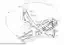
FIG. 4 is a schematic detailed perspective view of the connection between a railcar tank and a draft sill. Body bolster 62 extends transversely from and is perpendicular to draft sill apparatus 30. Body bolster 62 is welded to both draft sill apparatus 30 and bolster pad 50. Body bolster 62 includes bolster flange 64. Center plate 66 couples body bolster 62 to truck 14.
Reinforcing bars 60 extend longitudinally from front sill pad 52 along tank shell 18. Reinforcing bars 60 are welded to tank shell 18 and to draft sill apparatus 30.
Draft sill apparatus 30 includes draft sill tail 58 at the opposite end from the sill pocket.
The illustrated example shows how front sill pad 52 conforms to the curvature of tank head 42, which can be complex to manufacture.
FIG. 5 is a schematic perspective view of a draft sill and body bolster. Body bolster 62 includes body bolster web 68 and bolster flange 64.
Front draft lug 74 and rear draft lug 76 are located in the sill pocket. Cover plate 70 covers the top portion of the sill pocket. Striker 72 is positioned at the front end of the sill pocket and guides a coupler into the sill pocket.
FIG. 6 is a schematic perspective view of a tank with the draft sill and body bolster removed. The draft sill and body bolster are removed to illustrate reinforcing bars 60, bolster pad 50, front sill pad 52, and their welded connections to tank shell 18 and tank head 42.
As illustrated in FIGS. 3-6, head brace 54 is used because of the high susceptibility for fatigue cracks and/or fracture at the weld connection between draft sill apparatus 30 and front sill pad 52 and/or bolster pad 50.
This design has drawbacks. For example, precise fit-up is difficult to achieve between tank head 42 and front sill pad 52 because profiles may vary in shape and diameter. The longitudinal position of draft sill apparatus 30 relative to tank head 42 also introduces fit-up variation. Complex stress patterns develop at the welded connections, particularly between draft sill apparatus 30 and front sill pad 52. Multiple pass welds are needed, which increases the chances of weld defects.
The embodiments described herein include an improved tank car underframe. Particular embodiments eliminate the head brace and simplify the contour of the reinforcing pad. Particular embodiments include a tank car stub sill arrangement without a head brace where the tank rests on two vertical sill webs that are welded to reinforcing pads. The longitudinal attachment welds remain inboard of the body bolster webs. This reduces vertically oriented forces that can result in “Mode I” crack initiation and propagation. Vertical forces are carried by welds between the body bolster webs and the tank reinforcing pads and sill webs. The welds attaching the sill to the pads take mainly longitudinal loads. Particular embodiments and their advantages are best understood by reference to FIGS. 7 through 26, wherein like reference numbers indicate like features.
FIG. 7 is a schematic elevation view of an improved tank car underframe, according to particular embodiments. The tank car underframe includes front sill pad 82. Front sill pad 82 is shorter than conventional front sill pad 52. Front sill pad 82 extends between bolster pad 50 towards the end of tank shell 18 but does not extend past the end of tank shell 18 onto tank head 42. In other words, front sill pad 52 is located at a first end of tank shell 18 proximate tank head 42 and extends inboard longitudinally along the underside of tank shell 18. An advantage of this configuration is that front sill pad 82 is less complicated to manufacture than conventional front sill pad 52 because there is no need to match the curvature of tank head 42.
In addition, as illustrated front sill pad 82 is welded along its length to tank shell 18 but is not continuously welded to draft sill apparatus 30. Thus, longitudinal stress forces are not transmitted from draft sill apparatus 30 to front sill pad 82, which is an improvement over conventional designs.
FIG. 8 is a schematic perspective view of an improved tank car underframe, according to particular embodiments. The example illustrates the locations where body bolster web 68 is welded to bolster pad 50 and draft sill web 84 of draft sill apparatus 30. In addition, bolster pad 50 and front sill pad 82 are welded to tank shell 18. As described above, however, front sill pad 82 is not continuously welded to draft sill apparatus 30.
FIG. 9 is a schematic detailed view of a front sill pad and bolster web, according to particular embodiments. Body bolster web 68 is welded to bolster pad 50 and draft sill web 84. In the illustrated embodiment, body bolster web 68 includes notch 86 where the body bolster intersects with draft sill apparatus 30 and front sill pad 82. Notch 86 provides stress relief by preventing transfer of stress forces between body bolster web 68 and front sill pad 82.
FIG. 10 is a schematic end view of a body bolster, according to particular embodiments. The illustrated example includes section lines A-A, which section view is illustrated in FIGS. 14A and 14B.
FIG. 11 is a schematic top view of a body bolster, according to particular embodiments. The illustrated example includes top cover plate 88 and plate relief 90. In some embodiments, top cover plate 88 extends past body bolster 62.
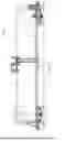
FIG. 12 is a schematic front view of a body bolster and tank, according to particular embodiments. The illustrated example includes section lines C-C, which section view is illustrated in FIG. 16.
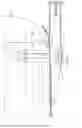
FIG. 13 is a schematic side view of a body bolster, draft sill apparatus, and tank, according to particular embodiments. The illustrated example includes: section lines E-E, which section view is illustrated in FIG. 17; section lines F-F, which section view is illustrated in FIG. 18; section lines G-G, which section view is illustrated in FIG. 19; and section lines K-K, which section view is illustrated in FIG. 20.
FIG. 14A is an example of cross section A-A indicated in FIG. 10, according to particular embodiments. FIG. 14B is another example of cross section A-A indicated in FIG. 10, according to particular embodiments.
FIG. 15A is an example of cross section B-B indicated in FIG. 11, according to particular embodiments. FIG. 15A also corresponds to the example in FIG. 14A.
FIG. 15B is another example of cross section B-B indicated in FIG. 11, according to particular embodiments. FIG. 15B also corresponds to the example in FIG. 14B.
FIG. 16 is an example of cross section C-C indicated in FIG. 12. In the illustrated example, there is not a weld between draft sill apparatus 30 and front sill pad 82 outboard of body bolster web 68.
FIG. 17 is an example of cross section E-E indicated in FIG. 13. The cross section view is outboard of the bolster web.
FIG. 18 is an example of cross section F-F indicated in FIG. 13. The cross section view is inboard of the bolster web.
FIG. 19 is an example of cross section G-G indicated in FIG. 13.
FIG. 20 is an example of cross section K-K indicated in FIG. 13.
Some embodiments accommodate heater coils around tank 12.
Some embodiments include additional bolsters. Examples are illustrated in FIGS. 21-26.
FIG. 21 is a schematic elevation view of an improved tank car underframe with additional bolsters, according to particular embodiments. The illustrated example includes fore bolster 92 and aft bolster 94.
Fore bolster 92 is welded to bolster pad 50 outboard of body bolster web 68. Aft bolster 94 is welded to bolster pad 50 inboard of body bolster web 68.
Fore bolster 92 and aft bolster 94 may be referred to as secondary bolsters. Fore bolster 92 and aft bolster 94 extend transversely from and perpendicular to draft sill apparatus 30. Fore bolster 92 is located outboard of body bolster web 68. Aft bolster 94 is located inboard of body bolster web 68.
FIG. 22 is a schematic perspective view of an improved tank car underframe with additional bolsters, according to particular embodiments. FIG. 22 illustrates a perspective view of fore bolster 92 illustrated in FIG. 21.
FIG. 23 is a schematic elevation view of an improved tank car underframe with an additional bolster and bolster pad, according to particular embodiments. The illustrated example includes secondary bolster pad 96 welded to tank shell 18 inboard of body bolster pad 50. Secondary bolster 98 is welded to secondary bolster pad 96 and draft sill assembly 30 (proximate draft sill tail 58).
FIG. 24 is a schematic perspective view of an improved tank car underframe with an additional bolster and bolster pad, according to particular embodiments. FIG. 24 illustrates a perspective view of secondary bolster 98 and secondary bolster pad 96 illustrated in FIG. 23.
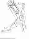
FIG. 25 is another schematic perspective view of an improved tank car underframe with an additional bolster and bolster pad, according to particular embodiments. The illustrated example includes secondary bolster pads 100 welded to tank shell 18 inboard of body bolster pad 50 and on either side of reinforcing bars 60. Secondary bolster 102 is welded to secondary bolster pads 100 and draft sill tail 58. The gap between secondary bolster 102 and reinforcing bars 60 reduces load transfer.
FIG. 26 is another schematic perspective view of an improved tank car underframe with an additional bolster and bolster pad, according to particular embodiments. In the illustrated example, secondary bolster pad 100 and secondary bolster 102 are located outboard of bolster pad 50.
Although the terms “bolster” and “secondary bolster” are used herein to differentiate bolsters of different sizes or proportions, both “bolster” and “secondary bolster” may be referred to as simply a “bolster” or “body bolster.” Accordingly, in some examples, the most outboard bolster may be referred to as a “body bolster,” no matter the size or proportion of the bolster. The phrase “a body bolster extending transversely from and perpendicular to the draft sill apparatus for supporting the tank” may refer to either body bolster or a secondary bolster, depending on the embodiment. In some embodiments, a bolster and a secondary bolster may be coupled to the same bolster pad (e.g., FIGS. 21 and 22) or a bolster and a secondary bolster may be coupled to different bolster pads (e.g., FIGS. 23-26).
In particular embodiments, the draft sill apparatus is described as not welded to the front sill pad outboard of the body bolster. Herein “not welded” means that the weld inboard of the body bolster does not continue outboard of the body bolster. Any small welds or mechanical connections outboard of the body bolster that are not continuous with the weld inboard of the body bolster and that do not permit significant force transfer from the draft sill apparatus to the front still pad are not considered for purposes of the embodiments and examples described herein. Furthermore, “welded inboard” of the body bolster means inboard and potentially including portions or all of the body bolster, but not outboard of the body bolster.
Modifications, additions, or omissions may be made to the systems and apparatuses disclosed herein without departing from the scope of the invention. The components of the systems and apparatuses may be integrated or separated. Moreover, the operations of the systems and apparatuses may be performed by more, fewer, or other components.
Although embodiments of the present disclosure and their advantages have been described in detail, it should be understood that various changes, substitutions and alternations can be made herein without departing from the spirit and scope of the invention as defined by the following example embodiments.
Claims
1. A railway tank car comprising:
a tank for transporting a commodity, the tank comprising a tank shell and at least one tank head;
a front sill pad welded to the underside of the tank shell, the front sill pad located at a first end of the tank shell proximate the tank head and extending inboard longitudinally along the underside of the tank shell;
a draft sill apparatus coupled to the underside of the tank shell at least partially by the front sill pad;
a body bolster extending transversely from and perpendicular to the draft sill apparatus for supporting the tank, the body bolster coupled to the draft sill apparatus; and
wherein the draft sill apparatus is welded to the front sill pad inboard of the body bolster and the inboard weld does not extend outboard of the body bolster.
2. The railway tank car of claim 1, wherein the body bolster comprises a notch where the body bolster intersects with the draft sill apparatus and the front sill pad.
3. The railway tank car of claim 1, wherein the body bolster comprises a body bolster web and a secondary bolster extending transversely from and perpendicular to the draft sill apparatus, the secondary bolster located outboard of the body bolster web.
4. The railway tank car of claim 1, wherein the body bolster comprises a body bolster web and a secondary bolster extending transversely from and perpendicular to the draft sill apparatus, the secondary bolster located inboard of the body bolster web.
5. The railway tank car of claim 1, further comprising a secondary bolster extending transversely from and perpendicular to the draft sill apparatus, the secondary bolster located inboard of the body bolster.
6. The railway tank car of claim 5, further comprising a pair of reinforcing bars parallel to each other and extending inboard from the front sill pad longitudinally along the underside of the tank shell, wherein the secondary bolster is not in contact with the pair of reinforcing bars.
7. The railway tank car of claim 5, wherein the draft sill apparatus comprises a draft sill tail at an inboard end of the draft sill apparatus and wherein the secondary bolster is coupled to the draft sill tail.
8. A tank car underframe, the underframe comprising:
a draft sill apparatus;
a body bolster coupled to the draft sill apparatus, the body bolster extending transversely from and perpendicular to the draft sill apparatus for supporting a tank;
a front sill pad coupled to the draft sill apparatus, the front sill pad positioned to extend longitudinally along an underside of the tank; and
wherein the draft sill apparatus is welded to the front sill pad inboard of the body bolster and the inboard weld does not extend outboard of the body bolster.
9. The tank car underframe of claim 8, wherein the body bolster comprises a notch where the body bolster intersects with the draft sill apparatus and the front sill pad.
10. The tank car underframe of claim 8, wherein the body bolster comprises a body bolster web and a secondary bolster extending transversely from and perpendicular to the draft sill apparatus, the secondary bolster located outboard of the body bolster web.
11. The tank car underframe of claim 8, wherein the body bolster comprises a body bolster web and a secondary bolster extending transversely from and perpendicular to the draft sill apparatus, the secondary bolster located inboard of the body bolster web.
12. The tank car underframe of claim 8, further comprising a secondary bolster extending transversely from and perpendicular to the draft sill apparatus, the secondary bolster located inboard of the body bolster.
13. The tank car underframe of claim 12, further comprising a pair of reinforcing bars parallel to each other and extending longitudinally inboard from the front sill pad, wherein the secondary bolster is not in contact with the pair of reinforcing bars.
14. The tank car underframe of claim 12, wherein the draft sill apparatus comprises a draft sill tail at an inboard end of the draft sill apparatus and wherein the secondary bolster is coupled to the draft sill tail.
Images & Drawings included:


Sources:
- United States Patent and Trademark Office - verify current appl. status at the USPTO↗
Recent applications in this class:
- » 20260131831 2026-05-14
RAILROAD CAR HAVING MULTIPLE PENETRATION RESISTANT AND PROTECTIVE STRUCTURES - » 20240043047 2024-02-08
RAIL VEHICLE CAR HAVING A TANK - » 20200298894 2020-09-24
Storage assembly for railcar - » 20150344042 2015-12-03
RAIL TANK CAR - » 20150083021 2015-03-26
Transport tanker reinforcement - » 20140338560 2014-11-20
Railroad tank car - » 20140318630 2014-10-30
Handling Bituminous Crude Oil in Tank Cars - » 20140000474 2014-01-02
Gussets for reinforcement in tank cars and tank cars including gussets - » 20110139032 2011-06-16
Railroad tank car - » 20100319571 2010-12-23
System and method for reinforcing railway tank cars