DISPENSING DEVICES, DISPENSING SYSTEMS, AND METHODS OF USE
US20260184489A1
2026-07-02
19/430,919
2025-12-23
Smart Summary: A new dispensing device is designed to release pressurized products from a canister. It has a housing that connects to the canister and features a window for dispensing. Inside the housing, there is an actuator that controls the flow of the product. The actuator can move between two positions: one where the nozzle is blocked and another where it is open for dispensing. Once the actuator is in the open position, it stays there until the user decides to change it back. 🚀 TL;DR
Abstract:
Dispensing devices for dispensing pressurized products from a container, dispensing systems including such dispensing devices, and methods of use. The dispensing device includes a housing configured to attach to a canister that contains a pressurized product. The housing defines an interior cavity and a window through a wall that surrounds the interior cavity. An actuator within the interior cavity has a passageway for delivering the pressurized product through the actuator and then through the window. The actuator is translatable between a first position in which a nozzle of the actuator is obstructed by the wall of the housing and a second position in which the nozzle is aligned with the window for dispensing the pressurized product through the window. After the actuator is translated to the second position, complementary features associated with the housing and actuator retain the actuator in a post-actuation position that is different than the first position.
Inventors:
- David Nance 5 🇺🇸 Chicago, IL, United States
- Chris Lutz 1 🇺🇸 Wentzville, MO, United States
Applicant:
Interested in similar patents?
Get notified when new applications in this technology area are published.
Classification:
F41H9/10 » CPC further
Equipment for attack or defence by spreading flame, gas or smoke or leurres ; Chemical warfare equipment Hand-held or body-worn self-defence devices using repellant gases or chemicals
B65D2401/45 » CPC further
Tamper-indicating means Windows in external skirts for viewing tamper-element
B65D2401/55 » CPC further
Tamper-indicating means based on a change or a contrast in colour
Description
CROSS-REFERENCE TO RELATED APPLICATIONS
This application claims the benefit of provisional U.S. Patent Application Ser. No. 63/740,007 filed Dec. 30, 2024, the contents of which are incorporated herein by reference.
BACKGROUND OF THE INVENTION
The present invention generally relates to dispensing systems. The invention particularly relates to dispensing devices adapted for dispensing pressurized products, such as a “pepper spray” or other irritant capable of use as a deterrent or incapacitant, and methods of dispensing such products.
Pressurized products are commonly dispensed from a container (e.g., a canister) with an actuator, for example a button, which is coupled to a valve stem connected to a valve within the container. Particular but nonlimiting examples include aerosol dispensing devices (also referred to herein as dispensers) adapted to dispense an aerosolized product (sometimes simply referred to as an aerosol) contained under pressure within an aerosol canister. Pressing the actuator moves the valve stem, often by a translation or deflection (bending) movement, which in turn opens the valve to allow the pressurized product to be dispensed through the valve, valve stem, and finally through a nozzle that is commonly located within the actuator. A potential problem with this arrangement arises if the product can be unintentionally discharged from the canister through the actions of a user or an errant object accidentally touching or pressing against the actuator. To avoid or at least reduce the risk of such incidents, it is well known to provide a protective cap that can be secured to the canister so as to surround the actuator to prevent or at least reduce the risk of an unintended actuation of the valve.
An issue arises with dispensers intended for single use, for example, when a canister that contains a pressurized product is intended to be used only once and then replaced. A notable example is when the pressurized product is an irritant (e.g., a pepper spray) used as a deterrent or incapacitant, in which case it can be critical that the user be aware whether the canister has been previously used and therefore does not contain a full charge of the pressurized product, and as a result may not contain a sufficient amount of the irritant to deter or incapacitate a threat.
In view of the above, it would be desirable if dispensers were available that were capable of notifying a user that the canister has been previously used and therefore does not contain a full charge of the pressurized product.
BRIEF SUMMARY OF THE INVENTION
The intent of this section of the specification is to briefly indicate the nature and substance of the invention, as opposed to an exhaustive statement of all subject matter and aspects of the invention. Therefore, while this section identifies subject matter recited in the claims, additional subject matter and aspects relating to the invention are set forth in other sections of the specification, particularly the detailed description, as well as any drawings.
The present invention provides, but is not limited to, dispensing devices (dispensers) for dispensing a pressurized product, such as an irritant (e.g., a pepper spray), from a container (canister), dispensing systems including such dispensing devices, and methods of using such dispensing devices.
According to one nonlimiting aspect, an irritant dispensing device is provided that includes a housing configured to attach to a canister that contains a pressurized irritant. The housing defines an interior cavity, a wall that surrounds the interior cavity, and a window through the wall and in communication with the interior cavity. An actuator is disposed within the interior cavity of the housing so as to be translatable relative to the housing and relative to the window of the housing in a translation direction. The actuator has a passageway therethrough for delivering the pressurized irritant through the actuator and then through the window. The passageway has an inlet adapted to receive the pressurized irritant and a nozzle adapted to dispense the pressurized irritant. The actuator is translatable in the translation direction relative to the housing between a first position in which the nozzle is obstructed by the wall of the housing and a second position in which the nozzle is aligned with the window of the housing for dispensing the pressurized irritant through the window. First and second complementary features associated with the housing and the actuator, respectively, are operable to resist translation of the actuator from the first position to the second position as the actuator is being forcibly translated in the translation direction to the second position, and to thereafter retain the actuator in a post-actuation position that is different than the first position.
According to another nonlimiting aspect, an irritant dispensing system is provided that includes an irritant dispensing device as described above and further includes a canister containing a pressurized irritant. The housing is attached to the canister and the inlet of the actuator is fluidically coupled to a valve stem of the canister.
According to yet another nonlimiting aspect, a method is provided for using an irritant dispensing system as described above. The method includes dispensing the pressurized irritant from the canister by pressing the actuator to cause the actuator to translate from the first position thereof to the second position thereof, and then releasing the actuator, wherein the actuator is retained in the post-actuation position thereof by the first and second complementary features associated with the housing and the actuator.
Technical aspects of dispensing devices, systems, and methods as described above preferably include the ability to notify a user that a canister has been previously used and therefore does not contain a full charge of the pressurized product.
These and other aspects, arrangements, features, and/or technical effects will become apparent upon detailed inspection of the figures and the following description.
BRIEF DESCRIPTION OF THE DRAWINGS
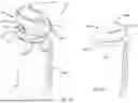
FIG. 1 schematically represents a dispensing system that includes a container (canister) that contains a pressurized product, and a dispensing device attached to the container according to a nonlimiting embodiment of the invention.
FIG. 2 schematically represents a top view of the dispensing system of FIG. 1, with a protective cap of the dispensing device omitted to expose an actuator within a housing of the dispensing device.
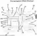
FIGS. 3A and 3B schematically represent longitudinal cross-sectional views of an upper portion of the dispensing system of FIG. 1, and schematically represent the actuator of the dispensing device in, respectively, a first “pre-actuation” position and a post-actuation position.
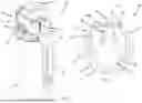
FIGS. 4A through 4C schematically represent the upper portion of the dispensing system of FIG. 1, and schematically represent the actuator of the dispensing device in, respectively, the first “pre-actuation” position, a second “actuated” position, and the post-actuation position.
FIGS. 5A through 5C schematically represent longitudinal cross-sectional views of the upper portion of the dispensing system of FIG. 1 with the actuator of the dispensing device shown in, respectively, the first “pre-actuation” position, the second “actuated” position, and the post-actuation position depicted in FIGS. 4A through 4C.
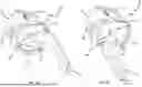
FIGS. 6A and 6B schematically represent isolated perspective views of the actuator of FIGS. 2 through 5C.
FIG. 7 schematically represents an isolated perspective view of the housing of FIGS. 2 through 5C.
FIGS. 8A and 8B schematically represent perspective bottom views of the dispensing device of FIGS. 1 through 5C as well as a clip depicted in FIGS. 1 and 2, wherein FIG. 8A depicts the clip in an installation position in preparation for securing the clip to the dispensing device, and FIG. 8B depicts the clip in an installed position in which the clip is secured to the dispensing device.
FIG. 9 schematically represents a longitudinal cross-sectional view of an upper portion of the dispensing system of FIG. 1, and depicts the clip in the installed position of FIG. 8B and secured to the dispensing device.
FIG. 10 schematically represents an isolated perspective view of the clip of FIGS. 8A, 8B, and 9.
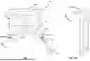
FIG. 11 schematically represents a dispensing system equipped with a dispensing device and clip secured thereto according to another nonlimiting embodiment of the invention.
FIG. 12 schematically represents an isolated perspective view of the clip of FIG. 11.
FIG. 13A is a side view of the dispensing device of FIG. 11 showing the dispensing device prior to installing the clip, and FIG. 13B is a side view of the dispensing device of FIG. 11 showing the device after installation of the clip.
DETAILED DESCRIPTION OF THE INVENTION
The intended purpose of the following detailed description of the invention and the phraseology and terminology employed therein is to describe what is shown in the drawings, which include the depiction of and/or relate to one or more nonlimiting embodiments of the invention, and to describe certain but not all aspects of the embodiment(s). The following detailed description also identifies certain but not all alternatives of the embodiment(s) depicted in the drawings. As nonlimiting examples, the invention encompasses additional or alternative embodiments in which one or more features or aspects shown and/or described as part of a particular embodiment could be eliminated, and also encompasses additional or alternative embodiments that combine two or more features or aspects shown and/or described as part of different embodiments. Therefore, the appended claims, and not the detailed description, are intended to particularly point out subject matter regarded to be aspects of the invention, including certain but not necessarily all of the aspects and alternatives described in the detailed description.
To facilitate the description provided below of the embodiment(s) represented in the drawings, relative terms, including but not limited to, “proximal,” “distal,” “anterior,” “posterior,” “vertical,” “horizontal,” “lateral,” “front,” “rear,” “side,” “forward,” “rearward,” “top,” “bottom,” “upper,” “lower,” “above,” “below,” “right,” “left,” etc., may be used in reference to the orientation of an irritant dispensing system during its use and/or as represented in the drawings. All such relative terms are useful to describe the illustrated embodiment(s) but should not be otherwise interpreted as limiting the scope of the invention.
FIGS. 1-13B depict various aspects of nonlimiting embodiments of a dispensing device (dispenser) 10 adapted to dispense a pressurized product from a container (referred to herein as a canister), as well as a dispensing system 20 equipped with the dispensing device 10 for dispensing a pressurized product from a canister 24. For convenience, consistent reference numbers are used throughout the drawings to identify the same or functionally related or equivalent elements. Furthermore, as a matter of convenience the dispensing device 10 and dispensing system 20 shown in the drawings will be described in reference to dispensing irritant aerosols (more simply, an irritant) that are capable of use as a deterrent or incapacitant, including pepper sprays, though it will be appreciated that the teachings of the invention are applicable to dispensing other types of products. In addition, it should be appreciated that the teachings of the invention are also generally applicable to dispensing a wide range of other types of products (e.g., liquids, foams, pastes, etc.) that are capable of being contained under pressure in a container.
With initial reference to a first embodiment represented in FIGS. 1 through 10, FIGS. 1, 2, 3A, and 3B, the system 20 is depicted as including the dispensing device 10 mounted on the canister 24, which as noted above may be an aerosol canister that contains an aerosol product (not shown) and, in the case of dispensing an irritant, typically also a propellant. The canister 24 may optionally be partially or fully enclosed within a housing that attaches to or is a component of the dispensing system 20 that includes the dispensing device 10. The canister 24 contains a valve assembly that includes a valve stem 30 configured to be actuated toward the canister 24 to release the irritant under pressure through the valve assembly and its valve stem 30. The valve assembly in its entirety is not shown in the drawings, and can be of a known or subsequently developed type of valve assembly capable of releasing the contents of a container under pressure and therefore will not be described in any detail here. In the nonlimiting embodiment shown, the dispensing device 10 is represented as further including a clip 22 that enables the dispensing system 20 to be secured to a belt, waistband, pocket, strap, or other similar configured object that a user may wish to secure the system 20 for rapid access to the system 20 in the event of a perceived threat.
In the nonlimiting embodiment shown in the drawings, the dispensing device 10 is represented as including a housing 12 adapted to securely attach the dispensing device 10 to the canister 24, and an actuator 14 disposed within an interior cavity 18 within the housing 12 and adapted to translate downward in what will be referred to herein as a translation direction 26 of the actuator 14 (FIGS. 3A and 3B) relative to the housing 12 by which the actuator 14 is able to selectively actuate the valve assembly of the canister 24 by pushing on the valve stem 30 in an axial direction of the stem 30. The interior cavity 18 is represented as being entirely surrounded by a wall 17 of the housing 12. Additionally, the dispensing device 10 is represented as including a protective cap 16 that encloses the actuator 14 within the housing 12 to prevent inadvertent actuation of the actuator 14. In the embodiment shown, the protective cap 16 is pivotally coupled to the housing 12 with pivot pins 15 (one of which is visible in FIG. 1) to enable access to the actuator 14 beneath the cap 16. As noted above, the housing 12 is adapted to securely attach the dispensing device 10 to the canister 24. For this purpose, the dispensing device 10 has a collar 19 disposed at a lower end of the housing 12 opposite the wall 17. Alternatively, it is foreseeable that the dispensing device 10 may be directly secured to a housing (not shown) that contains the canister 24 and forms an assembly with the dispensing device 10.
The actuator 14 includes a push button 32 to facilitate actuation of the actuator 14 relative to the housing 12 as a result of being pressed downward in the translation direction 26 of the actuator 14. The actuator 14 further includes a nozzle 34 that extends through and is circumferentially surrounded and completely enclosed by a tubular-shaped barrel 36 except for a distal end of the nozzle 34 that is exposed at an open end 36A of the barrel 36 and through which the irritant from the canister 24 is dispensed through an aperture (window) 40 defined through the wall 17 of the housing 12 and in communication with the interior cavity 18. To deliver the irritant from the valve stem 30 of the canister 24 to the nozzle 34, the actuator 14 has an internal passageway 42 therethrough for delivering the pressurized irritant through the actuator 14 and then through the window 40. For this purpose, the passageway 42 fluidically couples a passage of the nozzle 34 to an inlet 44 that is sized and configured to receive an upper end of the valve stem 30 for the purpose of receiving the pressurized irritant from the canister 24. The irritant then travels through the passageway 42 of the actuator 14 and then through the passage of the nozzle 34 before being dispensed through the window 40. It is important to note that there are multiple variations of the nozzle 34 possible other than the embodiment shown, and in some instances the actuator 14 may omit the nozzle 34. The dispensing device 10 may be fabricated so that the passage of the nozzle 34 has an appropriate inner diameter to create a particular spray pattern, for example, a relatively narrow pattern capable of traveling farther, or a relatively wide pattern to reduce the accuracy required of the user while still capable of disabling a threat. Furthermore, a particular irritant formula may be more effectively dispensed with a nozzle 34 having a particular internal diameter, e.g., in terms of length and/or diameter of its passage.
Whereas the upper end of the housing 12 is represented as open for enabling the interior cavity 18 to be accessed to permit actuation of the actuator 14 therein, the lower end of the housing 12 is closed by a base wall 28 except for an opening 29 through which the valve step 30 of the canister 24 protrudes into the cavity 18 for coupling with the inlet 44 of the actuator 14.
As evident from the above, the nozzle 34 is carried by the actuator 14 so that the nozzle 34 translates with the actuator 14 in the translation direction 26 relative to the housing 12 to actuate the valve stem 30. As such, both the actuator 14 and its nozzle 34 are both disposed within the interior cavity 18 of the housing 12 so as to be translatable relative to the housing 12 and relative to the window 40 of the housing 12 in the translation direction 26. The translation of the actuator 14 is preferably such that the actuator 14 is translatable in the translation direction 26 relative to the housing 12 between a first position (represented in FIGS. 3A, 4A, and 5A) in which the nozzle 34 is obstructed by the wall 17 of the housing 12 and a second position (represented in FIGS. 4B and 5B) in which the nozzle 34 is aligned with the window 40 of the housing 12 for dispensing the pressurized irritant through the window 40. The housing 12 and the actuator 14 are equipped with, respectively, first and second complementary features that are operable to resist translation of the actuator 14 from the first position to the second position as the actuator 14 is being forcibly translated in the translation direction 26 to the second position, and to thereafter retain the actuator 14 in a post-actuation position (represented in FIGS. 3B, 4C, and 5C) that is different than the first position, as is evident by comparing the first position in FIGS. 3A, 4A, and 5A with the post-actuation position in FIGS. 3B, 4C, and 5C).
In the nonlimiting embodiment shown, the complementary features associated with the housing 12 comprise at least one and preferably at least two slots 46 that are defined in the wall 17 of the housing 12 so as to be oriented parallel to the translation direction 26 of the actuator 14, and the complementary features associated with the actuator 14 comprise at least one and preferably two cantilevered arms 48 that are capable of elastically flexing in directions transverse to the translation direction 26. Furthermore, the slots 46 and cantilevered arms 48 have complementary latches 50 that retain the actuator 14 in the post-actuation position (FIGS. 3B, 4C, and 5C). The cantilevered arms 48 are represented as oriented parallel to the translation direction 26 of the actuator 14 and each is shown as translatably received in a respective one of the slots 46. From FIGS. 3A through 5C, it should be apparent that the slots 46, the cantilevered arms 48, and their latches 50 are arranged such that the post-actuation position is between the first and second positions and therefore different than the second position. In other words, the actuator 14 translates in the direction opposite the translation direction 26 if the actuator 14 is released following its arrival at the second position. Such an opposite translation can be the result of the valve stem 30 and/or additional biasing means incorporated into the dispensing device 10. However, it is also foreseeable that the slots 46, the cantilevered arms 48, and their latches 50 could be arranged such that the post-actuation position is the same as the second position, in other words, the slots 46, the cantilevered arms 48, and their latches 50 are arranged such that the actuator 14 is retained in the second position.
In comparing the first position represented in FIGS. 3A, 4A, and 5A and the second position represented in FIGS. 4B and 5B, it can be seen that the open end 36A of the barrel 36 in which the nozzle 34 is disposed is obstructed by the wall 17 of the housing 12 in the first position of the actuator 14, and the open end 36A of the barrel 36 is aligned with the window 40 of the housing 12 in the second position. Furthermore, the open end 36A of the barrel 36 is shown as aligned with the window 40 in the post-actuation position shown in FIGS. 3B, 4C, and 5C. A flange 36B is disposed at and surrounds the open end 36A of the barrel 36, and the barrel 36 and its flange 36B entirely close the window 40 of the housing 12 in the post-actuation position. The flange 36B is shown as oriented parallel to the translation direction 26 of the actuator 14 and received in a slot 52 defined within the housing 12 that adjoins the window 40 and is also oriented parallel to the translation direction 26 of the actuator 14, such that the flange 36B of the actuator 14 is translatably received within the slot 52 of the housing 12. As depicted in FIGS. 3A, 3B, 4B, and 4C, the nozzle 34 of the actuator 14 preferably bears a visible indicator, such as a coating or nozzle material of any desired color, for example, a bright red color, that is not visible through the window 40 when the actuator 14 is in the first position and is visible through the window 40 when the actuator 14 is in the post-actuation position. In this manner, once the actuator 14 has been actuated to dispense some or all of the pressurized irritant within the canister 24, the user is made aware that the canister 24 does not contain a full charge of the irritant, and as a result may not contain a sufficient amount of the irritant to deter or incapacitate a threat. Thus, the indicator on the nozzle 34 functions as a first-use indicator for the dispensing device 10, providing a clearly visible notice that the dispensing device 10 has been previously operated to release an irritant (or another product) from the cannister 24. Additionally, the flange 36B blocks access to the exterior of the barrel 36, preventing or at least inhibiting the ability to tamper with the barrel 36, nozzle 34, and first-use indicator to ensure that a user cannot be deceived or mistakenly believe that irritant has not been previously dispensed from the canister 24.
To facilitate alignment and translation of the actuator 14 relative to the housing 12, the housing 12 and actuator 14 are represented as equipped with complementary features that are operable to facilitate alignment of the actuator 14 with the housing 12 during assembly of the actuator 14 with the housing 12, and thereafter maintain alignment of the actuator 14 relative to the housing 12 as the actuator 14 is forcibly translated in the translation direction 26 to the second position. In the nonlimiting embodiment shown, the complementary features associated with the housing 12 comprise at least one post and preferably three posts 54 that are oriented parallel to the translation direction 26 of the actuator 14, and the complementary features associated with the actuator 14 comprise at least one bore and preferably three bores 56 that are also oriented parallel to the translation direction 26 of the actuator 14, such that the posts 54 of the housing 12 are translatably received within the bores 56 of the actuator 14 after the housing 12 and actuator 14 are assembled together as shown in FIGS. 3A and 3B.
As noted in reference to FIGS. 1 and 2, the housing 12 further comprises a collar 19 that extends in a direction opposite the wall 17 to enable the housing 12 to be attached to the canister 24. As represented in FIGS. 8A and 8B, the collar 19 defines a peripheral opening 60, a first channel 62A extending circumferentially in a first circumferential direction from the peripheral opening 60, and a second channel 62B extending circumferentially in a second circumferential direction from the peripheral opening 60. As evident from FIG. 8B, the peripheral opening 60 is located on the rears side of the housing 12 and therefore diametrically opposite the window 40 through which the irritant is dispensed by the dispensing device 10. An end 22A of the clip 22 is receivable through the peripheral opening 60 and thereafter is selectively circumferentially translatable within each of the first and second channels 62A and 62B. Each of the first and second channels 62A and 62B has a detent 64 configured to retain the end 22A of the clip 22 therein. In this manner, the clip 22 is able to serve as a low-profile, removable feature for securing the dispensing system 20 to a belt, waistband, pocket, strap, or other similar configured object that a user may wish to secure the system 20 for rapid access to the system 20 in the event of a perceived threat. The ability to secure the clip 22A on either side of the peripheral opening 60, and therefore also on either side of the window 40, configures the dispensing device 10 for ambidextrous use clip. The clip 22 can also be easily removed by a user if desired, providing further flexibility in use.
From the forgoing, it can be appreciated that an irritant dispensing system such as represented in FIGS. 1 and 2 can be obtained by assembling a canister (e.g., 24) containing the pressurized irritant with the dispensing device 10 as described above, which entails attaching the housing 12 of the device 10 to the canister 24 so that the inlet 44 of the actuator 14 is fluidically coupled to the valve stem 30 of the canister 24. In this process, the housing 12 is attached to the canister 24 with the collar 19, which extends from the housing 12 in a direction opposite the wall 17 of the housing 12. Additionally, the clip 22 can be attached to the housing 12 by inserting the end 22A of the clip 22 through the peripheral opening 60 of the collar 19 and then circumferentially translating the end 22A of the clip 22 within either of the first and second channels 62A and 62B. By translating the end 22A of the clip 22 beyond the detent 64 of that channel 62A/62B, the clip 22 is able to be retained in that channel 62A/62B.
As evident from FIG. 3A, initial assembly of the dispensing device 10 on the canister 24 results in the inlet 44 of the actuator 14 being seated on the valve stem 30 of the canister 22. As evident from FIG. 3B, the valve stem 30 becomes fully inserted into the inlet 44 of the actuator 13 as a result of actuating the actuator 14, during which the actuator 14 translates in the translation direction 26 from the first position toward the second position. Thereafter, use of the irritant dispensing system entails dispensing the pressurized irritant from the canister by pressing the actuator 14 to cause the actuator 14 to translate from the first position thereof (FIGS. 3A, 4A, and 5A) to the second position thereof (FIGS. 4B and 5B), after which releasing the actuator 14 results in the actuator 14 being retained in the post-actuation position thereof (FIGS. 3B, 4C, and 5C) by the complementary latches 50 of the slots 46 and cantilevered arms 48 associated with the housing 12 and actuator 14, respectively. As apparent from FIGS. 3A through 4C, the nozzle 34 and the indicator (e.g., any desired color, for example, red) that it bears is not visible through the window 40 when the actuator 14 is in the first position, and becomes visible through the window 40 when the actuator 14 is in the post-actuation position.
FIGS. 11 through 13B depict a dispensing system 20 representative of a second embodiment of the invention. In view of similarities between the first and second embodiments depicted in the drawings, the following discussion of FIGS. 11 through 13B will focus primarily on aspects of the second embodiment that differ from the first embodiment in some notable or significant manner. Other aspects of the second embodiment not discussed in any detail can be, in terms of structure, function, materials, etc., essentially as was described for the first embodiment.
In the second embodiment of FIGS. 11 through 13B, the dispensing device 10 as having a modified collar 19 that defines a recessed peripheral (circumferential) channel 160 (visible in FIG. 13A) between first and second ribs 19A and 19B of the collar 19 that are spaced apart in an axial direction of the device 10. The peripheral channel 160 is configured to assemble with a clip 122 having a C-shaped portion 122A that is receivable within the peripheral channel 160 to secure the clip 122 to the collar 19. The C-shaped portion 122A of the clip 122 and at least one of the first and second ribs 19A and 19B of the collar 19 have at least one set of complementary retention features 122B and 160A that prevent the C-shaped portion 122A of the clip 122 from translating (rotating) in a circumferential direction within the peripheral channel 160 of the collar 19. In the embodiment shown, the C-shaped portion 122A has a pair of retention features 122B in the form of notches that are diametrically opposite each other on separate legs 122C of the clip 122, and the second rib 19B of the collar 19 has four equi-angularly spaced retention features 160A that enable the clip 122 to be installed at three different angular-spaced locations on the device 10, for example, on the left, right, or back side of the dispensing system 20. The clip 122 is installed by sliding the C shaped portion 122A into the peripheral channel 160 at the desired position. Once the two retention features (notches) 122B of the clip 122 engage two of the mating retention features 160A of the collar 19, the clip 122 is fully retained within the peripheral channel 160 between the first and second ribs 19A and 19B of the collar 19. Removal of the clip 122 can be performed by spreading the legs 122C of the C shaped portion 122A apart to disengage the retention features (notches) 122B of the clip 122 from the retention features 160A of the collar 19 and then sliding the clip 122 off the collar 19.
In view of the above, the dispensing device 10 represented in the drawings provides various different advantageous features.
-
- First-Use Indicator: The actuator 14 features a nozzle 34 that is concealed in the pre-actuation first position (FIG. 4A), and that only becomes visible through the window 40 as a result of the actuator 34 being actuated to release the contents of the canister 24 (FIGS. 4B and 4C). The visibility of the nozzle 34 and the indicator it bears is maintained after actuation through an internal locking system comprising the latches 50 of the slots 46 and cantilevered arms 48, which ensures that the nozzle 34 remains visible within the window 40 after some or all of the contents of the canister 24 have been dispensed. In this manner, the visibility of the nozzle 34 serves as an unmistakable sign of prior use. Additionally, the flange 36B of the barrel 36 blocks access to the exterior of the barrel 36, preventing or at least inhibiting the ability to tamper with the barrel 36, nozzle 34, and first-use indicator to reduce the risk that a user might be deceived or mistakenly believe that irritant has not been previously dispensed from the canister 24.
- Safety Guard Below Spray Nozzle: The flange 36B of the barrel 36 that surrounds the nozzle 34 serves as a rigid safety guard positioned directly beneath the nozzle 34. In this position, the flange 36B is able to inhibit if not completely prevent an attempt to manually reposition the actuator 14 to its pre-actuation first position after the first actuation of the actuator 14. In this manner, the flange 36B ensures the integrity of the first-use indication provided by the nozzle 34 and prevents tampering or deceptive resetting of the actuator 14.
- Alignment Features for Installation: The complementary slots 46 and arms 48, complementary posts 54 and bores 56, and complementary slot 52 and flange 36B of the housing 12 and actuator 14, respectively, ensure proper orientation of the actuator 14 with the valve stem 30 of the canister 24 during installation of the dispensing device 10 on the canister 24. These features further ensure that the inlet 44 of the actuator 14 will properly align with the valve stem 30 of the canister 24 (FIG. 3A) so that the actuator 14 will be fully seated onto the valve stem 30 during actuation, creating a secure seal for optimal spray performance. These features ensure that the actuator 14 will reliably actuate and dispense the contents of the canister 24 on the first press of the push button 32 and reduce potential assembly errors during manufacturing.
- Low-Profile Ambidextrous Belt Clip: In the first embodiment of FIGS. 1 through 10, the peripheral opening 60 and channels 62A and 62B of the collar 19 of the housing 12 provide a rear-entry snap-fit attachment for the clip 22 and allow for ambidextrous use of the dispensing device 10. The clip 22 can be installed on either side of the canister 24, accommodating user preference. In the second embodiment of FIGS. 11 through 13B, the peripheral channel 160 and of the collar 19 and the C-shaped portion 122A of the clip 122 also provide snap-fit attachment for the clip 122 and allow for ambidextrous use of the dispensing device 10, while further enabling the clip 122 to be installed in one of three different angular-spaced locations relative to the canister 24 to accommodate user preference. The clips 22 and 122 can also be easily removed without affecting the overall functionality of the dispenser system 20, catering to users who do not require a belt clip.
As previously noted above, though the foregoing detailed description describes certain aspects of one or more particular embodiments of the invention, alternatives could be adopted by one skilled in the art. For example, the dispensing system 20, dispensing device 10, and their components could differ in appearance and construction from the embodiment described herein and shown in the drawings, functions of certain components of the dispensing system 20 and dispensing device 10 could be performed by components of different construction but capable of a similar (though not necessarily equivalent) function, and various materials could be used in the fabrication of the dispensing system 20, dispensing device 10, and/or their components. As such, and again as was previously noted, it should be understood that the invention is not necessarily limited to any particular embodiment described herein or illustrated in the drawings.
Claims
1. An irritant dispensing device comprising:
a housing configured to attach to a canister that contains a pressurized irritant, the housing defining an interior cavity, a wall surrounding the interior cavity, and a window through the wall and in communication with the interior cavity;
an actuator disposed within the interior cavity of the housing so as to be translatable relative to the housing and relative to the window of the housing in a translation direction, the actuator comprising a passageway therethrough for delivering the pressurized irritant through the actuator and then through the window, the passageway comprising an inlet adapted to receive the pressurized irritant and a nozzle adapted to dispense the pressurized irritant, the actuator being translatable in the translation direction relative to the housing between a first position in which the nozzle is obstructed by the wall of the housing and a second position in which the nozzle is aligned with the window of the housing for dispensing the pressurized irritant through the window; and
first and second complementary features associated with the housing and the actuator, respectively, the first and second complementary features being operable to resist translation of the actuator from the first position to the second position as the actuator is being forcibly translated in the translation direction to the second position, and to thereafter retain the actuator in a post-actuation position that is different than the first position.
2. The irritant dispensing device of claim 1, wherein the first complementary features associated with the housing comprise at least a first slot oriented parallel to the translation direction of the actuator, the second complementary features associated with the actuator comprise at least a first cantilevered arm, and the first cantilevered arm and the first slot have complementary latches that retain the actuator in the post-actuation position.
3. The irritant dispensing device of claim 2, wherein the first cantilevered arm is oriented parallel to the translation direction of the actuator and is translatably received in the first slot.
4. The irritant dispensing device of claim 1, wherein the post-actuation position is different than the second position and is between the first and second positions.
5. The irritant dispensing device of claim 1, further comprising third and fourth complementary features associated with the housing and the actuator, respectively, the third and fourth complementary features being operable to maintain alignment of the actuator relative to the housing as the actuator is forcibly translated in the translation direction to the second position.
6. The irritant dispensing device of claim 5, wherein the third complementary features associated with the housing comprise at least a first post oriented parallel to the translation direction of the actuator, the fourth complementary features associated with the actuator comprise at least a first bore oriented parallel to the translation direction of the actuator, and the first post of the housing is translatably received within the first bore of the actuator.
7. The irritant dispensing device of claim 1, wherein the actuator further comprises:
a barrel in which the nozzle is disposed, the barrel defining an open end that is obstructed by the wall of the housing in the first position of the actuator and is aligned with the window of the housing in the second position; and
a flange disposed at and surrounding the open end of the barrel, the flange and the barrel entirely closing the window of the housing in the post-actuation position.
8. The irritant dispensing device of claim 7, wherein the flange is oriented parallel to the translation direction of the actuator, the housing comprises a slot adjoining the window and oriented parallel to the translation direction of the actuator, and the flange of the actuator is translatably received within the slot of the housing.
9. The irritant dispensing device of claim 1, wherein the actuator bears an indicator that is not visible through the window when the actuator is in the first position and is visible through the window when the actuator is in the post-actuation position.
10. The irritant dispensing device of claim 9, wherein the indicator is a color.
11. The irritant dispensing device of claim 1, wherein the housing further comprises a collar that extends in a direction opposite the wall and is adapted to attach the housing to the canister.
12. The irritant dispensing device of claim 11, wherein the collar defines a peripheral channel between first and second ribs of the collar.
13. The irritant dispensing device of claim 12, further comprising a clip having a C-shaped portion receivable within the peripheral channel of the collar and adapted to secure the clip to the collar.
14. The irritant dispensing device of claim 13, wherein the C-shaped portion of the clip and at least one of the first and second ribs of the collar have complementary retention features that prevent the C-shaped portion of the clip from translating in a circumferential direction within the peripheral channel of the collar.
15. An irritant dispensing system comprising the irritant dispensing device of claim 1, the irritant dispensing system further comprising the canister containing the pressurized irritant, wherein the housing is attached to the canister and the inlet of the actuator is fluidically coupled to a valve stem of the canister.
16. A method of using the irritant dispensing system of claim 15, the method comprising:
dispensing the pressurized irritant from the canister by pressing the actuator to cause the actuator to translate from the first position thereof to the second position thereof; and
releasing the actuator, wherein the actuator is retained in the post-actuation position thereof by the first and second complementary features associated with the housing and the actuator.
17. The method of claim 16, wherein the inlet of the actuator is seated on the valve stem of the canister in the first position, and the valve stem is inserted into the inlet of the actuator as the actuator is translated from the first position to the second position.
18. The method of claim 16, wherein the post-actuation position is different than the second position and is between the first and second positions.
19. The method of claim 16, wherein the actuator bears an indicator that is not visible through the window when the actuator is in the first position and is visible through the window when the actuator is in the post-actuation position.
20. The method of claim 16, wherein before the dispensing step the method further comprises:
attaching the housing to the canister with a collar that extends from the housing in a direction opposite the wall, the collar defining a peripheral channel; and
attaching a clip to the housing by installing a C-shaped portion of the clip in the peripheral channel and retaining the clip in the peripheral channel with complementary retention features on the C-shaped portion and the collar that prevent the clip from translating in a circumferential direction within the peripheral channel.
Images & Drawings included:


Sources:
- United States Patent and Trademark Office - verify current appl. status at the USPTO↗
Similar patent applications:
- » 20080173663
Cap dispensing devices useful in system and method for dispensing prescriptions - » 20200193765
Bill validation and cash dispensing device, system and method for use in a casino context - » 20180082516
Bill validation and cash dispensing device, system and method for use in a casino context - » 20190057573
Bill validation and cash dispensing device, system and method for use in a casino context - » 20060241807
Devices useful in system and method for dispensing prescriptions - » 20080067190
Devices useful in system and method for dispensing prescriptions - » 20080061075
Devices useful in system and method for dispensing prescriptions - » 20080061078
Devices useful in system and method for dispensing prescriptions - » 20080061077
Devices useful in system and method for dispensing prescriptions - » 20240124215
PEPPER SPRAY DISPENSING SYSTEMS AND DEVICES AND METHODS OF USE