ENERGY EFFICIENT LITHIUM CHLORIDE ELECTROLYTIC PROCESS AND ELECTROLYZER PLANT
US20260185255A1
2026-07-02
19/129,981
2023-05-11
Smart Summary: A new method helps turn lithium chloride into lithium hydroxide using less energy. It works by first creating a weak lithium chloride solution in a part of the electrolyzer. This solution is then made stronger through a process called flash evaporation, which uses heat generated during the electrolyzer's operation. The stronger solution is sent back to the electrolyzer for further processing. By using the heat that would normally be wasted, this method saves energy during the conversion. 🚀 TL;DR
Abstract:
An apparatus and method for converting lithium chloride into lithium hydroxide by electrolysis in an energy efficient manner. A dilute lithium chloride solution produced in the anolyte compartment of the electrolyzer cell is concentrated by means of flash evaporation using heat generated by the operation of the electrolyzer cell. The concentrated lithium chloride solution is recycled to the electrolyzer cell. The use in the flash evaporation of heat energy that would otherwise be released to the environment and wasted results in reduced energy consumption for the conversion process.
Inventors:
- Ian Bailey 3 🇨🇦 Vancouver, Canada
- Warren WOLFS 3 🇨🇦 Vancouver, Canada
- Clive BRERETON 3 🇨🇦 Vancouver, Canada
Applicant:
Interested in similar patents?
Get notified when new applications in this technology area are published.
Classification:
C25B15/087 » CPC main
Operating or servicing cells; Supplying or removing reactants or electrolytes; Regeneration of electrolytes Recycling of electrolyte to electrochemical cell
C25B1/16 » CPC further
Electrolytic production of inorganic compounds or non-metals; Products; Alkali metal compounds Hydroxides
C25B1/46 » CPC further
Electrolytic production of inorganic compounds or non-metals; Products; Simultaneous production of alkali metal hydroxides and chlorine, oxyacids or salts of chlorine, e.g. by chlor-alkali electrolysis in diaphragm cells
C25B9/19 » CPC further
Cells or assemblies of cells; Constructional parts of cells; Assemblies of constructional parts, e.g. electrode-diaphragm assemblies; Process-related cell features; Cells comprising dimensionally-stable non-movable electrodes; Assemblies of constructional parts thereof with diaphragms
C25B9/67 » CPC further
Cells or assemblies of cells; Constructional parts of cells; Assemblies of constructional parts, e.g. electrode-diaphragm assemblies; Process-related cell features; Constructional parts of cells Heating or cooling means
C25B15/08 IPC
Operating or servicing cells Supplying or removing reactants or electrolytes; Regeneration of electrolytes
Description
FIELD OF THE INVENTION
The invention pertains to apparatuses and processes for the production of lithium hydroxide from lithium chloride in electrochemical systems.
BACKGROUND OF THE INVENTION
Electrolysis is an effective means to carry out various industrially useful processes. Examples include the electrolysis of brine in the chloralkali process, the decomposition of water into hydrogen and oxygen, electrometallurgical processes for the production of metals, and electroplating. Electrolyzers can carry out non-spontaneous reactions to separate chemical species by the application of an electrical current. They can be used to deal with unique chemistries and provide high efficiency and selectivity.
One example of growing importance is the electrolysis of lithium salts. Lithium components are used for various industrial applications, including chemical processing, medicine, nuclear industry, air purification and the manufacture of rechargeable batteries.
The importance of lithium hydroxide (LiOH) has increased due to the recent focus on electrification of energy systems, which require reliable solutions for energy storage in the form of lithium-ion rechargeable batteries. The demand for lithium-ion batteries has been driven by the growing market for portable electronic devices, electric vehicles, and large-scale energy storage systems. These forms of energy storage, coupled with sources of clean and renewable energy, can significantly reduce the environmental footprint of many processes.
High-performance batteries with higher energy density and longer cycle life often require higher-purity lithium hydroxide, which can only be produced using sophisticated processing techniques such as electrochemical processing of lithium chloride (LiCl) to produce high-purity lithium hydroxide.
Electrolyzers are net consumers of energy as they use electrical power to carry out chemical reactions. Energy consumption is determined by the inherent electrochemistry of the process, the size of the plant, the concentration of the species to be treated, the performance of the electrolyzer cell, the energy management of the process plant, and energy rejection on site. The efficiency of the electrochemical cell is governed by the selectivity of the chemical reactions taking place, the efficiency of the ion exchange membrane, the cell current efficiency, the process temperature, the cell and electrodes design, and other process parameters that are specific to each application.
One of the main challenges of industrial electrolyzer plants is the overall energy use, which dictates the operating costs of the plant and determines the process economics of large-scale applications. This is a critical challenge since there are important trade-offs associated with the energy balance of the plant that can allow for efficiency gains that can make certain configurations more attractive.
As electrochemical applications of LiCl electrolysis require management of species concentration to maintain a suitable water-balance in the plant, it is often challenging to implement suitable processes that can maintain the water-balance of the plant in an energy efficient manner. It would be desirable to allow for the use of a weak brine of LiCl with significant water content in the feed, and manage the water balance in an efficient manner, without requiring the addition of solid salts or the use of a salt crystallizer. Moreover, reducing the total volume of weak brine to be circulated and treated in the plant, or the duty of the salt lixator loop, can be important to reduce capital and operating costs.
There is a need in the industry for an effective apparatus and method for the conversion of lithium chloride into lithium hydroxide in an energy efficient manner that allows for reduced energy consumption, improved process intensification, and lower cost.
SUMMARY OF THE INVENTION
The invention provides an apparatus and method for electrolytic conversion of a salt into ions to produce an intended reaction product.
According to one aspect of the invention, there is provided an apparatus for electrolytic conversion of a salt into its corresponding ions to produce an intended reaction product, comprising: an electrolyzer cell comprising an anolyte compartment, a catholyte compartment, and at least one ion exchange membrane between the compartments; an anolyte tank for supplying an anolyte to the anolyte compartment; means for feeding a catholyte to the catholyte compartment; a vacuum flash evaporator for evaporating water from the anolyte product received from the anolyte compartment using heat generated by operation of the electrolyzer cell to produce a concentrated anolyte product; a stream fluidly connecting the anolyte compartment to the vacuum flash evaporator for supplying the anolyte product to the vacuum flash evaporator; means for circulating the concentrated anolyte product from the vacuum flash evaporator to the anolyte tank; and means for circulating the concentrated anolyte product from the anolyte tank to the electrolyzer cell.
According to another aspect of the invention, there is provided a method for electrolytic conversion of a salt into its corresponding ions to produce an intended reaction product, comprising: feeding an anolyte to an anolyte compartment of an electrolyzer cell; feeding a catholyte to a catholyte compartment of the electrolyzer cell; electrolyzing the anolyte and catholyte in the electrolyzer cell to produce an anolyte product and a catholyte product; supplying the anolyte product to a vacuum flash evaporator by a stream fluidly connecting the anolyte compartment to the vacuum flash evaporator; increasing the concentration of the anolyte product by vacuum evaporation in the vacuum flash evaporator using heat generated in the electrolysis to produce a first concentrated anolyte product; and recirculating the first concentrated anolyte product to the electrolyzer cell.
In preferred embodiments of the apparatus and method, the salt is LiCl and the corresponding base that is produced is LiOH. In other embodiments, the salts may be NaCl and KCl with corresponding bases NaOH and KOH.
The invention provides an apparatus and method for converting LiCl into LiOH by electrolysis, in which the dilute LiCl solution produced in the anolyte compartment of the electrolyzer cell is concentrated by means of flash evaporation using heat generated by the operation of the electrolyzer cell. The concentrated solution is recycled to the electrolyzer cell. This use of heat energy which would otherwise be released to the environment and wasted provides for reduced energy consumption.
Moreover, since the lithium species downstream of the electrolyzer cell are not sent back to brine treatment or salt dissolving unit operations, this reduces the total water content and volumetric flow of brine to treat in the primary and secondary brine pre-treatment and purification units, reduces the equipment size, and can reduce the amount of purge required to control impurities in the process.
According to one aspect of the invention, there is provided an apparatus for electrolytic conversion of lithium chloride into lithium hydroxide, comprising: an electrolyzer cell comprising an anolyte compartment, a catholyte compartment, and at least one ion exchange membrane between the compartments; an anolyte tank for supplying an anolyte comprising lithium chloride and water to the anolyte compartment; means for feeding a catholyte to the catholyte compartment; a vacuum flash evaporator for evaporating water from the anolyte product received from the anolyte compartment using heat generated by operation of the electrolyzer cell to produce a concentrated anolyte product; a stream fluidly connecting the anolyte compartment to the vacuum flash evaporator for supplying the anolyte product to the vacuum flash evaporator; means for circulating the concentrated anolyte product from the vacuum flash evaporator to the anolyte tank; and means for circulating the concentrated anolyte product from the anolyte tank to the electrolyzer cell.
According to another aspect of the invention, there is provided a method for electrolytic conversion of lithium chloride into lithium hydroxide, comprising: feeding an anolyte comprising lithium chloride and water to an anolyte compartment of an electrolyzer cell; feeding a catholyte to a catholyte compartment of the electrolyzer cell; electrolyzing the anolyte and catholyte in the electrolyzer cell to produce an anolyte product comprising lithium chloride and water and a catholyte product comprising lithium hydroxide; supplying the anolyte product to a vacuum evaporator by a stream fluidly connecting the anolyte compartment to the vacuum flash evaporator; increasing the concentration of the anolyte product by vacuum evaporation in the vacuum flash evaporator using heat generated by the electrolyzer to produce a first concentrated anolyte product; and recirculating the first concentrated anolyte product directly back to the electrolyzer cell.
Further aspects of the invention and features of specific embodiments of the invention are described below.
BRIEF DESCRIPTION OF THE DRAWINGS
Exemplary embodiments are illustrated in referenced figures of the drawings. It is intended that the embodiments and figures disclosed herein are to be considered illustrative rather than restrictive.
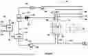
FIG. 1 is a schematic diagram of an electrolyzer plant and process according to an embodiment of the invention. An anolyte vacuum flash evaporator is utilized in the electrolysis loop to manage the water balance without sending anolyte back to brine treatment.
FIG. 2 is a schematic diagram of an electrolyzer plant and process according to an embodiment of the invention. A liquid-to-liquid heat recovery exchanger is used to transfer heat from the catholyte loop to the anolyte system for increased evaporation.
FIG. 3 is a schematic diagram of an electrolyzer plant and process according to an embodiment of the invention. Trim coolers and heaters are used to balance the heat requirements of the plant.
FIG. 4 is a schematic diagram of an electrolyzer plant and process according to an embodiment of the invention. An anolyte product evaporator is utilized in the electrolysis loop to manage the water balance without sending anolyte back to brine treatment.
FIG. 5 is a schematic diagram of an embodiment of an electrolyzer cell of the electrolyzer plant.
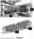
FIG. 6 are two images of electrochemical systems for lithium electrolysis as described in the Example. The top photo shows a pilot plant used for demonstration LiCl electrolysis processes. The bottom image depicts a 3-D model of a plant with 2×50 electrolyzer cell carriages.
DETAILED DESCRIPTION
FIGS. 1 to 5 illustrate embodiments of the apparatus 10 for electrolytic conversion of LiCl into LiOH, with co-production of hydrogen gas and chlorine gas. The system utilizes heat that is generated in the electrolyzer to concentrate the anolyte solution, thereby maximizing energy efficiency. The apparatus 10 has an electrolyzer cell 12 which comprises an anolyte compartment 14, a catholyte compartment 16 and an ion exchange membrane 18 separating the two compartments. An anode 20 is exposed to anolyte in the anolyte compartment and a cathode 22 is exposed to catholyte in the catholyte compartment. A source of electric power 24 is connected to the electrolyzer cell 12 to maintain an electrical potential difference across it.
The electrolyzer cell 12 does not require a particular ion exchange membrane or geometry. Suitable ion exchange membranes include cation-selective exchange membrane (CEM) that are commercially available under the product names Nafion™, Fumatech™, Neosepta™, Flemion™, and Aciplex™. Likewise, the electrochemical cell can have more than one ion exchange membrane.
The electrolyzer cell 12 does not require a particular cell configuration. Suitable configurations may be 2-compartment electrolyzers, or electrolyzers with more than two compartments such as 3-compartment electrolyzers and other configurations known in the art. The electrolyzer cell 12 does not require a particular electrode type.
An evaporator system 26 is provided to increase the concentration of the feed LiCl brine solution, because such solutions, as commercially available, are typically of much lower concentration than what is required for effective electrolysis. This feature allows for steady state operation without the need to import solid salts into the process. The evaporator system 26 comprises an evaporator 28 connected to a source of low concentration LiCl solution 30 and a source of energy 32. The evaporator 28 evaporates water 34 from the LiCl brine solution, producing a stream of preconcentrated LiCl solution 36, having a LiCl concentration that is higher than that of the low concentration solution 30. Concentration ranges for the LiCl solution 30 should be below the solubility limit of the salt, preferably between 1% w/w and 50% w/w, and most preferably between 5% w/w and 10% w/w. Concentration ranges for the LiCl solution 36 should be below the solubility limit of the salt, preferably between 1% w/w and 50% w/w, and most preferably between 20% w/w and 35% w/w.
The preconcentrated LiCl solution 36 is fed to an anolyte tank 38. As explained below, a stream of recirculated anolyte solution is also fed into the anolyte tank 38, so the final concentration of the anolyte LiCl solution 42 prior to electrolysis is achieved in the anolyte tank 38. An anolyte pump 40 is arranged to pump a stream of anolyte feed 42 from the anolyte tank 38 through a conduit 39 to the anolyte compartment 14 of the electrolyzer cell 12.
A catholyte 44 is fed from a catholyte source 41 through a conduit 43 to the catholyte compartment 16 of the electrolyzer cell. The catholyte is a weak caustic solution of LiOH and water.
Referring to FIGS. 1 to 5, the anolyte feed 42, comprising a relatively strong brine solution of LiCl and water, flows into the anolyte compartment 14. Concentration ranges for the LiCl solution 42 should be below the solubility limit of the salt, preferably between 10% w/w and 30% w/w, and most preferably between 15% w/w and 25% w/w. The catholyte feed 44, comprising a weak caustic solution of LiOH and water, flows into the catholyte compartment 16. The electrolysis reaction in the electrolyzer cell 12 produces, from the anolyte compartment, an anolyte product stream 46 comprising a relatively weak brine solution of LiCl and water, and chlorine gas 48, which exit from the cell from the anolyte fluid outlet 47. There is produced from the catholyte compartment a relatively strong caustic solution 50 of LiOH and water, which exits the cell through the catholyte fluid outlet 49, and hydrogen gas 52. LiOH concentration in the product solution 50 is in the range of up to 20% w/w, and most preferably between 3% w/w and 10% w/w.
The product streams 46, 50 have an increased temperature as a result of heat generated by the operation of the electrolyzer cell 12. This heat is used to concentrate the anolyte product stream 46, as explained below.
The following principal reactions occur in the electrolyzer as shown in FIGS. 1 to 5:
In the anode compartment:
In the cathode compartment:
To maintain the charge balance in the electrolyzer cell, lithium ions are transferred across the ion exchange membrane 18. The product gases, namely, hydrogen and chlorine, are produced in an equimolar ratio.
The overall reaction is: 2 LiCl+2 H2O→H2+Cl2+2 LiOH
It will be understood that this reaction can be carried out in a number of different electrolyzer cell configurations.
The electrolysis process accordingly produces a LiOH solution and two gases, hydrogen and chlorine. The electrolysis reaction products may be used in various separate or downstream processes. For example, the LiOH solution may be crystallized to produce battery-grade lithium hydroxide monohydrate. The gases may be used to produce hydrochloric acid, which may be sold as a plant product and/or recycled back to the electrochemical process. The hydrogen gas may also be used in hydrogen fuel cells and other applications for pure hydrogen gas.
In some embodiments of the electrolysis process, the following temperature and pressure operating conditions may be used. The electrolyzer cell 12 operates at a temperature of 1° C. to 99° C., alternatively 30° C. to 95° C., alternatively 60° C. to 90° C. The pressure in the anolyte compartment 14 is between 0 kPa(g) and 300 kPa(g), alternatively between 0 kPa(g) and 200 kPa(g), alternatively between 0 kPa and 40 kPa(g). Similar pressure ranges are observed in the catholyte compartment, while a pressure differential between compartments is tightly controlled for specific considerations of cell design and mechanical integrity and process safety.
Referring to FIGS. 1 to 3, an anolyte evaporation system 53 is provided to concentrate the anolyte product stream 46, prior to its recirculation to the electrolyzer cell. The pressure of the product stream 46 is reduced by means of a flash valve 54, and the reduced pressure stream is fed to a vacuum flash evaporator 56. The pressure reduction is controlled to a vacuum condition to maximize water evaporation. The pressure may be reduced to between 0.1 kPa(a) and 100 kPa(a), preferably between 1 kPa(a) and 50 kPa(a), and most preferably between 1 kPa(a) and 20 kPa(a). A vacuum pump 58 and vacuum condenser 60 are arranged to maintain a vacuum in the flash evaporator and allow for evaporation of water at normal process temperatures. Typical process temperatures are under 100° C., preferably under 90° C. and most preferably be tween 70 and 90° C. This system for evaporating water utilizes heat generated in the electrolyzer, since the heat energy in the anolyte product stream 46 assists in the evaporation of water from it.
The evaporation of water in the vacuum flash evaporator 56 from the anolyte product stream 46 produces a concentrated anolyte stream 62, which is fed through a conduit 63 to the anolyte tank 38. This stream 62 mixes with the preconcentrated LiCl solution 36 in the anolyte tank to produce the anolyte feed 42 that is pumped through a conduit 39 to the electrolyzer.
Since the concentrated anolyte stream 62 is added to the preconcentrated anolyte 36 from the evaporator system 26, for recirculation to the electrolyzer cell, a given final concentration of anolyte feed 42 to the electrolyzer cell can be achieved with less evaporation in the evaporator system 26, thereby reducing the energy required for the evaporation and accordingly for the overall electrolysis process.
In some embodiments of the flash evaporation process, the following operating conditions may be used. The anolyte vacuum flash pressure is between 0.1 kPa(a) and 100 kPa(a), alternatively between 1 kPa(a) and 50 kPa(a), alternatively between 1 kPa(a) and 20 kPa(a). The increase in concentration of LiCl produced by the flash evaporator 28 may be between 10 wt. % and 20 wt. %.
FIG. 2 illustrates an embodiment of the invention that further increases the energy efficiency of the plant. In some applications, the catholyte feed 41 is of higher temperature than required for the electrolysis process, and requires cooling. Rather than rejecting heat to the environment, the embodiment depicted in FIG. 2 transfers heat from the catholyte feed 41 to the anolyte product stream 46 to increase its temperature going to evaporator by means of a liquid-to-liquid heat recovery heat exchanger 80. In some embodiments of the invention, the catholyte stream 41 could be up to 10° C. to 40° C. hotter than anolyte product stream 46, allowing for higher temperatures going to the vacuum flash evaporator 56, increased evaporation in the evaporator 56, and lower overall energy consumption at the energy source 32. It is also noted that the electrochemical cell can be designed to maximize the heat transfer 99 through the membrane from the catholyte loop to the anolyte loop to maximize energy recovery.
FIG. 3 illustrates an embodiment of the invention that assists in the management of the temperature profile of the plant by means of trim coolers/heaters 81, 82 and 83 in the anolyte product stream 46, the anolyte feed 42 and the catholyte feed 44, respectively. These trim coolers/heaters ensure operability of the plant during start-up of the plant, and ensures that the heat balance of the plant allows for maximum energy efficiency.
FIG. 4 illustrates an embodiment of the invention that, in addition to using the heat in the anolyte product 46, uses external heat to provide evaporation of the anolyte product 46. This is done in an anolyte evaporation system 53 comprising an anolyte loop evaporator 70, by means of external heat 72, evaporating water 71 and producing a concentrated anolyte stream 63. The system is substantially the same as that depicted in FIG. 1, except that the anolyte product 46 is heated by external heat and the evaporator system does not have a flash valve and vacuum flash evaporator.
Example
The electrochemical cells and methods of the present invention were developed and tested in the pilot plant shown in FIG. 6. The pilot system treated LiCl brine for conversion into LiOH product.
The LiCl feed quality at the electrolysis battery limits was treated to reduce the levels of divalent cations (i.e., Mg2+ and Ca2+) and silica. These impurities if left in the brine to electrolysis would shorten membrane lifetime, increase the operating voltage, and decrease the current efficiency over time. The anolyte concentration was controlled and the electrolyte density of the anolyte purge was used to control the dilution of the feed for composition control.
The lithium chloride solution (referred to as the anolyte) and the product lithium hydroxide solution (referred to as the catholyte) were circulated through the two compartments of a NORSCAND® Electrolyzer. In each cell, the anolyte and catholyte solutions flowed from bottom to the top of the cell through the anolyte and catholyte compartments respectively. The two compartments are separated by a cation-selective exchange membrane (CEM). The anolyte compartment contains a chlorine-evolving Dimensionally Stable Anode (DSA) coated titanium mesh electrode. The catholyte compartment contains a 316L mesh stainless steel electrode. When DC power was applied to the electrolyzer via the rectifier (and the potential is above the minimum required for electrolysis) current flowed through the electrolyzer. The electrical potential caused the oxidation of chlorine ions (Cl—) on the surface of the anode to produce chlorine (Cl2) and reduction of water on the cathode to produce hydrogen (H2) and hydroxide (OH—), as shown in the chemical equations below:
In the anode compartment:
In the cathode compartment:
The overall reaction is: 2 LiCl+2 H2O→H2+Cl2+2 LiOH
The current is transferred from the electrodes to the solution via the anode and cathode reactions. It passes through the membrane primarily as a flow of lithium ions. The lithium ions that pass through the membrane combine with the hydroxide ions formed on the cathode to form lithium hydroxide. Water also passes through the membrane alongside the lithium. In the absence of make-up and withdrawal of lithium or water feed/product solutions, the concentration of lithium in the anolyte would decrease and the concentration of lithium in the catholyte would increase.
Referring to FIG. 6, the NORSCAND® LiCl electrochemical cell 12 utilized electrolyser cells of commercial size area connected to a rectifier and associated AC transformer. DC power 24 was delivered to the electrolyser by a rectifier. The plant also includes associated equipment 70, including anolyte circulation pump, anolyte heat exchangers, anolyte storage tanks, chlorine handling systems, catholyte circulation pump, catholyte heat exchangers, hydrogen gas handling systems, seal pots, dosing pumps, catholyte stripper, concentration analyzers, instrumentation, safety systems and automatic controls.
The electrolysers were operated with controls on current density and voltage to maintain adequate operation of the system.
As chlorine gas was generated on the anode, a two-phase mixture of anolyte and chlorine gas was formed in the anolyte compartment of the cell. The two-phase mixture left the cell and was collected in a manifold/piping system. The gas was substantially separated from the liquid anolyte in a de-gasifier header and tee. The gas, saturated chlorine, was collected with the remaining cell lines and the anolyte circulation tank vent in a chlorine header. The pressure of the chlorine header was controlled with a pressure control device, which provided the back pressure on the anolyte compartment of the cells.
A two-phase mixture was formed in the catholyte compartment as hydrogen gas evolves on the cathode. This two-phase mixture exited each cell and was collected in a manifold/piping system. The gas was substantially separated from the liquid catholyte in a de-gasifier header and tee. The pressure of the hydrogen header was controlled with a pressure control device, which provided the back pressure on the catholyte compartment of the cells.
All the above pilot plant operations in this Example were carried out using instrumentation and equipment that allowed for the safe operation and handling with the product gases chlorine and hydrogen.
Throughout the foregoing description and the drawings, in which corresponding and like parts are identified by the same reference characters, specific details have been set forth in order to provide a more thorough understanding to persons skilled in the art. However, well known elements may not have been shown or described in detail to avoid unnecessarily obscuring the disclosure. Accordingly, the description and drawings are to be regarded in an illustrative, rather than a restrictive, sense.
As will be apparent to those skilled in the art in the light of the foregoing disclosure, many alterations and modifications are possible in the practice of this invention without departing from the scope thereof. Accordingly, the scope of the invention is to be construed in accordance with the following claims.
Claims
1. An apparatus for electrolytic conversion of lithium chloride into lithium hydroxide, comprising:
(a) an electrolyzer cell comprising an anolyte compartment, a catholyte compartment, and at least one ion exchange membrane between the compartments;
(b) an anolyte tank for supplying an anolyte comprising lithium chloride and water to the anolyte compartment;
(c) means for feeding a catholyte to the catholyte compartment;
(d) a vacuum flash evaporator for evaporating water from the anolyte product received from the anolyte compartment using only heat generated by operation of the electrolyzer cell to produce a concentrated anolyte product;
(e) a stream fluidly connecting the anolyte compartment to the vacuum flash evaporator for supplying the anolyte product to the vacuum flash evaporator;
(f) means for circulating the concentrated anolyte product from the vacuum flash evaporator to the anolyte tank; and
(g) means for circulating the concentrated anolyte product from the anolyte tank to the electrolyzer cell.
2. An apparatus according to claim 1, wherein the catholyte comprises lithium hydroxide and water.
3. An apparatus for electrolytic conversion of lithium chloride into lithium hydroxide, comprising:
(a) an electrolyzer cell comprising:
(i) an anolyte compartment having an anode arranged for contact with an anolyte comprising lithium chloride and water in said anolyte compartment;
(ii) a catholyte compartment having a cathode arranged for contact with a catholyte in said catholyte compartment; and
(iii) an ion exchange membrane separating the anolyte compartment and the catholyte compartment;
(b) means for connecting the electrolyzer cell to a source of electrical power for maintaining an electric potential difference across the electrolyzer cell;
(c) an anolyte tank;
(d) means for feeding the anolyte from the anolyte tank to the anolyte compartment;
(e) means for feeding the catholyte to the catholyte compartment;
(f) a catholyte fluid outlet at the catholyte compartment for flowing a catholyte product out of the catholyte compartment;
(g) an anolyte fluid outlet at the anolyte compartment for flowing an anolyte product comprising a solution of lithium chloride and water out of the anolyte compartment;
(h) an anolyte evaporation system arranged to receive the anolyte product from the anolyte fluid outlet, comprising vacuum flash evaporator configured to evaporate water from the anolyte product using only heat generated by operation of the electrolyzer cell, for producing a concentrated anolyte product having an increased concentration of lithium chloride;
(i) a stream fluidly connecting the anolyte compartment to the vacuum flash evaporator for supplying the anolyte product to the vacuum flash evaporator; and
(j) means for feeding the concentrated anolyte product from the vacuum flash evaporator to the anolyte tank.
4. An apparatus according to claim 3, wherein the catholyte product comprises an aqueous solution of lithium hydroxide.
5. An apparatus according to claim 3, wherein the vacuum flash evaporator is operatively connected to a vacuum condenser and a vacuum pump.
6. An apparatus according to claim 1, wherein the vacuum flash evaporator is arranged to receive only the anolyte product.
7. An apparatus according to claim 1, further comprising an evaporator system arranged to increase a concentration of lithium chloride in a dilute aqueous solution of lithium chloride, wherein the evaporator system comprises an evaporator and means for feeding a preconcentrated lithium chloride aqueous solution having an increased concentration of lithium chloride, as produced by the evaporator, to the electrolyzer cell.
8. An apparatus according to claim 1, further comprising a flash valve for reducing the pressure of the anolyte product received from the anolyte compartment.
9. An apparatus according to claim 1, further comprising a liquid-to-liquid heat recovery heat exchanger for transferring heat from the catholyte feed to the anolyte product.
10. An apparatus according to claim 1, wherein the electrochemical cell is a 3-compartment cell.
11. A method for electrolytic conversion of lithium chloride into lithium hydroxide, comprising:
(a) feeding an anolyte comprising lithium chloride and water to an anolyte compartment of an electrolyzer cell;
(b) feeding a catholyte to a catholyte compartment of the electrolyzer cell;
(c) electrolyzing the anolyte and catholyte in the electrolyzer cell to produce an anolyte product comprising lithium chloride and water and a catholyte product comprising lithium hydroxide;
(e) supplying the anolyte product to a vacuum evaporator by a stream fluidly connecting the anolyte compartment to the vacuum flash evaporator;
(f) increasing the concentration of the anolyte product by vacuum evaporation in the vacuum flash evaporator using only heat generated in step (c) to produce a first concentrated anolyte product; and
(g) recirculating the first concentrated anolyte product to the electrolyzer cell).
12. A method according to claim 11, further comprising the step of flowing the anolyte product through a flash valve to reduce its pressure before supplying it to the vacuum flash evaporator.
13. A method for electrolytic conversion of lithium chloride into lithium hydroxide, comprising:
(a) providing an electrolyzer cell comprising:
(i) an anolyte compartment having an anode arranged for contact with an anolyte (42) comprising lithium chloride and water in said anolyte compartment;
(ii) a catholyte compartment having a cathode arranged for contact with a catholyte in said catholyte compartment; and
(iii) an ion exchange membrane separating the anolyte compartment and the catholyte compartment;
(b) maintaining an electric potential difference across the electrolyzer cell;
(c) feeding the anolyte from an anolyte tank to the anolyte compartment;
(d) feeding the catholyte to the catholyte compartment;
(e) operating the electrolyzer cell to convert the lithium chloride into lithium hydroxide and produce hydrogen gas and chlorine gas;
(f) flowing an anolyte product comprising an aqueous solution of lithium chloride out of the anolyte compartment and through a flash valve to reduce its pressure;
(g) flowing the anolyte product after step (f) to a vacuum flash evaporator, and evaporating water out of said anolyte product in the vacuum flash evaporator using only heat generated by operation of the electrolyzer cell, thereby producing a concentrated anolyte product having an increased concentration of lithium chloride; and
(h) flowing the concentrated anolyte product from the vacuum flash evaporator to the anolyte tank for recirculation to the electrolyzer cell.
14. A method according to claim 11, wherein the vacuum flash evaporator receives only the anolyte product.
15. A method according to claim 13, further comprising:
(i) feeding an aqueous solution of lithium chloride to an evaporator;
(j) evaporating water from said aqueous solution and thereby producing a concentrated aqueous solution having an increased concentration of lithium chloride; and
(k) feeding said concentrated aqueous solution from the evaporator to the anolyte tank.
16. A method according to claim 11, wherein the electrolyzer cell operates at a temperature in the range of 1° C. to 99° C.
17. A method according to claim 11, wherein the electrolyzer cell operates at a temperature in the range of 30° C. to 95° C.
18. A method according to claim 11, wherein the electrolyzer cell operates at a temperature in the range of 60° C. to 90° C.
19. A method according to claim 11, wherein a pressure in the anolyte compartment is in the range of 0 kPa(g) to 300 kPa(g).
20. A method according to claim 11, wherein a pressure in the anolyte compartment is in the range of 0 kPa(g) to 200 kPa(g).
21. A method according to claim 11, wherein a pressure in the anolyte compartment is in the range of 0 kPa(g) to 40 kPa(g).
22. A method according to claim 11, wherein a pressure in the vacuum flash evaporator is in the range of 0.1 kPa(a) to 100 kPa(a).
23. A method according to claim 11, wherein a pressure in the vacuum flash evaporator is in the range of 1 kPa(a) to 50 kPa(a).
24. A method according to claim 11, wherein a pressure in the vacuum flash evaporator is in the range of 1 kPa(a) to 20 kPa(a).
25. A method according to claim 11, wherein the vacuum flash evaporator increases the concentration of lithium chloride in the anolyte product (46) by 10 wt. % to 30 wt. %.
26. A method according to claim 11, wherein the vacuum flash evaporator (56) reduces the pressure of the anolyte product (46) to a pressure in the range of 0.1 kPa(a) and 100 kPa(a).
27. A method according to claim 11, wherein the vacuum flash evaporator (56) reduces the pressure of the anolyte product (46) to a pressure in the range of 1 kPa(a) and 20 kPa(a).
28. A method according to claim 11, wherein the step of evaporation is done at a temperature less than 100° C.
29. A method according to claim 11, wherein the step of evaporation is done at a temperature less than 90° C.
30. A method according to claim 11, wherein the step of evaporation is done at a temperature in the range of 70° C. to 90° C.
31. A method according to claim 11, wherein the concentration of LiCl in the anolyte is below the solubility limit of the LiCl.
32. A method according to claim 11, wherein the concentration of LiCl in the anolyte is in the range of 10 wt. % and 30 wt. %.
33. A method according to claim 11, wherein the concentration of LiCl in the anolyte is in the range of 15 wt. % and 25 wt. %.
34. A method according to claim 15, wherein the concentration of LiCl in the aqueous solution of LiCl is below the solubility limit of the LiCl.
35. A method according to claim 15, wherein the concentration of LiCl in the aqueous solution of LiCl is in the range of 1 wt. % and 40 wt. %.
36. A method according to claim 15, wherein the concentration of LiCl in the aqueous solution of LiCl is in the range of 5 wt. % and 10 wt. %.
37. A method according to claim 15, wherein the concentration of LiCl in the concentrated aqueous solution is below the solubility limit of the LiCl.
38. A method according to claim 15, wherein the concentration of LiCl in the concentrated aqueous solution is in the range of 1 wt. % to 40 wt. %.
39. A method according to claim 15, wherein the concentration of LiCl in the concentrated aqueous solution is in the range of 20 wt. % to 35 wt. %.
40. A method according to claim 13, wherein the concentration of LiOH in the catholyte product is up to 20 wt. %.
41. A method according to claim 13, wherein the concentration of LiOH in the catholyte product is in the range of 3 wt. % and 10 wt. %.
42. A method according to claim 13, wherein the produced hydrogen gas and chlorine gas are used to synthesize HCl.
43. A method according to claim 11, further comprising cooling the catholyte feed in a liquid-to-liquid heat exchanger to transfer heat to the anolyte product to increase the evaporation achieved in the vacuum flash evaporator.
44. A method according to claim 11, wherein the electrochemical cell (12) is a 3-compartment cell.
Images & Drawings included:


Sources:
- United States Patent and Trademark Office - verify current appl. status at the USPTO↗
Recent applications in this class:
- » 20260168119 2026-06-18
Electrolyzer Loop Augmentation for Chemical Production Line with Carbon Monoxide Tail Gas - » 20250369141 2025-12-04
RECYCLING OF POLYMER MEMBRANES COMPRISING METAL-CONTAINING CATALYST MATERIAL - » 20250270723 2025-08-28
ELECTROLYSER AND METHOD FOR OPERATING AN ELECTROLYSER - » 20250207280 2025-06-26
ELECTROLYTE REGENERATION - » 20250137153 2025-05-01
HYDROGEN GENERATION AND CARBON DIOXIDE STORAGE SYSTEM WITH INCREASED PROCESSING CAPACITY OF CARBON DIOXIDE - » 20250051945 2025-02-13
BUILT-IN ELECTROLYZER FOR INCREASING DURABILITY OF A FLOW BATTER BY REBALANCING THE ELECTROLYTE COMPOSITION - » 20240318340 2024-09-26
CARBON DIOXIDE CONVERSION DEVICE - » 20240301577 2024-09-12
RECIRCULATED SOLID OXIDE ELECTROLYZER CELL SYSTEM AND METHOD - » 20230313399 2023-10-05
APPARATUSES, SYSTEMS, AND METHODS FOR GENERATING NITRIC OXIDE - » 20230235469 2023-07-27
METHOD FOR OPERATING A WATER ELECTROLYSIS DEVICE