DOSING APPARATUS
US20260185286A1
2026-07-02
19/425,153
2025-12-18
Smart Summary: A dosing apparatus is designed to deliver liquids to machines, like washing machines. It has a control unit that manages how different liquids mix and flow to the machine. There are multiple inlets for connecting to containers of these liquids, and an outlet where the mixed liquid comes out. A pump helps move the liquid from the outlet to the machine when needed. Additionally, a pressure sensor checks the liquid flow and sends information back to the control unit. 🚀 TL;DR
Abstract:
A dosing device for dosing and supplying media via fluid lines to at least one target device, in particular to a textile washing machine, including a control unit, a mixing distribution device with multiple inlets, an outlet and an actuator that can be actuated by the control unit and that switches different communication paths between the inlets and the outlet. The inlets can be connected to containers for the media. A pump arranged downstream of the outlet can be actuated by the control unit as a result of a request command for a medium received from the target device to convey the medium. In a fluid line section downstream of the outlet a pressure sensor is arranged and connected to the control unit.
Applicant:
Interested in similar patents?
Get notified when new applications in this technology area are published.
Classification:
D06F39/088 » CPC main
Details of washing machines not specific to a single type of machines covered by groups - ; Liquid supply or discharge arrangements Liquid supply arrangements
D06F2103/14 » CPC further
Parameters monitored or detected for the control of domestic laundry washing machines, washer-dryers or laundry dryers Supply, recirculation or draining of washing liquid
D06F2105/42 » CPC further
Systems or parameters controlled or affected by the control systems of washing machines, washer-dryers or laundry dryers Detergent or additive supply
D06F39/08 IPC
Details of washing machines not specific to a single type of machines covered by groups - Liquid supply or discharge arrangements
Description
The invention relates to a dosing device for dosing and supplying media or media solutions to at least one target device according to Claim 1.
Dosing devices for feeding and dosing media to a target device have been developed and manufactured by the applicant for decades.
Known-type dosing devices can successively supply different media, for example detergent components or washing or cleaning agents, to a target device, e.g. a washing machine. In washing or cleaning processes, a metered addition of an exactly predetermined amount of medium is desired at specified times in order to achieve the desired washing or cleaning effect.
The dosing device according to the invention serves to supply different media, i.e. different chemicals, to one target device or multiple target devices. Different media can have different viscosities and also different temperature-dependent viscosities.
It is known to use so-called mixing distribution devices, as described, for example, in the Applicant's EP 2 783 142A1 .
The known mixing distribution devices comprise a movable actuator that can switch different communication paths between one of the inlets of the mixing distribution device and the outlet of the mixing distribution device. The actuator can, for example, be provided by a rotatable disk that is made, for instance, of ceramic.
The known dosing device comprises at least one pump, e.g. a hose pump, which is arranged downstream of the outlet of the mixing distribution device in order to convey medium or rinse medium.
The Applicant has also developed dosing devices which use multiple pumps downstream of the mixing distributor. For example, reference is made here to DE 10 2015 110 862 A1 originating from the Applicant.
Starting from a dosing device of the prior art, the object of the invention is to provide a dosing device which is of simple construction and ensures reliable dosing.
The invention achieves this object with the features of Claim 1.
The principle of the invention essentially consists in providing a pressure sensor that is arranged downstream of the outlet of the mixing distribution device. The pressure sensor can measure the pressure prevailing in a section of fluid line. The pressure sensor is connected to the control unit and can transmit information about the measured pressure to the control unit.
With knowledge of the prevailing line pressure downstream of the outlet, or after receiving information about the pressure, the control unit can reduce the delivery rate of the pump if necessary.
An elevated pressure can occur, for example, if fluid lines between the mixing distribution device and a target device are not laid properly. Specifically, dosing devices could be arranged in the basement of a building and centrally supply multiple target devices, e.g. multiple textile washing machines, with media, with the washing machines located on higher floors and in some cases very far away from the dosing device (for example, tens of meters away from the dosing device). The fluid line sections can thus be laid over several meters of height difference and along numerous curved or bent, even angular, line sections. With particularly unfavorable or incorrect line installations, a very high pressure can result in the fluid line sections due to the aforementioned installation issues.
In the event that the pump conveys against this high pressure, the dosing device, the subsequent fluid line sections, or even the target devices can be damaged. For example, it has happened that fluid lines have burst due to the high pressure, or leaks have occurred.
Similar problems can arise if there is an issue with the fluid line in the area of the target device, e.g. at the inlet of the target device, and the fluid cannot be conveyed properly. Here too, a pressure increase can occur with undesired consequences.
Finally, the Applicant has determined that during the conveying of certain media—especially media that have a particularly high viscosity that may also be temperature-dependent—when conveying such media, a plug formation occurs due to a phase or boundary layer formation (for example, between the rinse medium and the medium). Such a medium plug, as a result of blocking the fluid line path and impeding conveyance, can likewise cause undesired high pressures with the described adverse consequences.
Due to the fact that a pressure sensor is provided according to the invention, the control unit can initiate a regulation of the pump as a result of receiving information about the prevailing line pressure. For example, the control unit can reduce the pump output by a certain value, e.g. by 20% or 40% or 60%. This can in particular lead to the control unit stipulating that, when the pump's delivery rate is reduced, its pump running time is extended in order to convey the desired, predetermined amount of medium to the target device.
By conveying the medium at a reduced pump output over a longer pump time, the line pressure prevailing in the fluid line system is not unnecessarily increased further, but rather the conveyance is carried out in a measured way, thereby preventing the above-described problems from occurring.
In addition, the control unit can document the measured high pressure value or an exceedance of a threshold value for a pressure. For this purpose, the control unit can be equipped with a memory. In particular, the control unit can also utilize an event log and store corresponding events there. An event to be stored can include, for example, that a reduction of the pump delivery rate has been carried out. This can indirectly serve as information about an exceedance of a pressure threshold value.
According to the invention, the information stored in the memory can be retrievable. It can, for example, also be transmitted to an external computer. It can, for example, also be retrieved to aid in searching for faults in the line installation or to carry out a search for faults in the line connections to the target devices.
Also, if necessary, the control unit can, in the event that a threshold value is exceeded in the pressure measurement, initiate the generation of an alarm signal.
The mixing distribution device has a rinse medium inlet, which is connected via a pipe separation device to the domestic water supply, in particular with the interposition of a pipe separation device.
The dosing device according to the invention comprises a mixing distribution arrangement that has multiple inlets and at least one outlet. For example, the mixing distribution arrangement can comprise an inlet disk and an outlet disk that is rotatable relative to it.
In particular, the mixing distribution arrangement comprises an actuator that switches different communication paths in different set positions. Different inlets can be brought into communication with the outlet of the mixing distribution arrangement in different positions of the actuator. The mixing distribution arrangement has multiple inlets on its input side. Several different containers are connected to these inlets. Different media are located in the containers, in particular.
In particular, the control unit can cause a flushing of the line paths each time after a medium has been conveyed through the mixing distribution arrangement. A through-channel in the mixing distribution arrangement can be flushed with rinse medium, especially water, each time after a medium has been conveyed. In this way, it can be ensured that no unintentional contact between different media occurs.
The dosing device according to the invention can, with the aid of the pump, successively supply the different media to the target device.
In one embodiment of the invention, a first mixing distribution arrangement and a second mixing distribution arrangement are provided and are in particular connected in series.
The dosing device according to the invention can optionally have all features of dosing devices as described in the patent applications of the Applicant listed below: DE 10 2011 108 396A1, DE 10 2011 119 021A1, DE 10 2011 122 921 A 1, DE 10 2012 012 913A1, DE 10 2014 002 560A1, DE 10 2014 010 126A1, DE 10 2015 107 105A1, DE 10 2015 107 976A1, DE 10 2016 102 829A1, DE 10 2017 114 767A1, DE 10 2017 103 168A1, DE 10 2017 114 665A1, DE 10 2018 113 644A1, DE 10 2018 122 651A1, DE 10 2020 107 555A1, DE 10 2020 107 558A1, DE 10 2023 123 774A1, as well as DE 10 2024 110 910A1 .
The aforementioned patent applications of the Applicant are hereby included in the disclosure content of the present patent application—in order to avoid repetition; this explicitly also for the purpose of incorporating features from the referenced dosing devices of the Applicant into the content of the present patent application, including into the claims, if needed.
In particular, it is pointed out that the mixing distribution arrangements described in the present patent application can have a construction, design, and mode of operation like the mixing distribution arrangements according to the referenced patent applications.
The dosing device according to the invention serves for the dosing and supplying of media or media solutions. These can in particular be chemicals, e.g. detergent components or detergents or cleaning agents, but equally also disinfectants or other chemicals.
The dosing device according to the invention serves to supply the medium or the media solution to one or more target devices. The target device can, for example, be a washing machine or a dishwasher, or a mop preparation system or another washing or cleaning system. The dosing device according to the invention can also be configured to provide a cleaning agent or disinfectant solution or the like. The dosing device comprises at least one control unit, which for example includes a microprocessor or a differently designed computing unit.
Furthermore, the dosing device comprises a mixing distribution device.
A mixing distribution device suitable for use with the dosing device according to the invention is described, for example, in the Applicant's WO 2012/062265A2.
A further suitable mixing distribution device is described in the Applicant's WO 2013/075692A2. The aforementioned patent applications of the Applicant are hereby included in the disclosure content of the present patent application—in order to avoid repetition; this explicitly also for the purpose of incorporating features from the referenced dosing devices of the Applicant into the content of the present patent application, including into the claims, if needed.
Other mixing distribution devices are also suitable for use in the dosing device according to the invention, provided that they can switch different communication paths between one of the multiple inlets of the mixing distribution device and an outlet of the mixing distribution device in the manner required by the claims.
It is particularly advantageous if the actuator, which is flowed through by a medium, has a through-channel that can be flushed with the rinsing agent.
By regularly flushing this through-channel as well, a safe operation of the dosing device is ensured.
The inlets of the mixing distribution device can be connected to containers for the media. These can, for example, be conventional containers of predetermined sizes. The inlets can be connected to the containers e.g. via hose lines, in particular with the aid of suction lances.
The mixing distribution device can, for example, comprise two, five, or seven or any other number of inlets for connection to different media containers.
At least one of the inlets is configured as a rinse medium inlet. According to the invention, the rinse medium inlet can be connected via a rinse medium line and a pipe separation device to a domestic water network or to a supply of rinse medium.
To perform a flushing, the control unit of the dosing device can first move the actuator into a flushing position. With the actuator in the flushing position, the rinse medium inlet is in communication with the outlet of the mixing distribution device.
The control unit can then actuate the valve to open, thereby freeing the rinse medium line, and actuate the pump to convey rinse medium.
In this way, a flushing of the mixing distribution device, especially its through-channels, is made possible.
After a predetermined time period elapses, the pump can stop and the actuator can be actuated and moved into a park position.
If the control unit of the dosing device receives a request command for a specific medium from a target device, the control unit can first actuate the actuator, moving it into a product position in which a communication connection is established between the container in which the requested medium is located and the outlet of the mixing distribution device. Then the control unit can initiate operation of the pump for a predetermined period of time in order to convey a requested amount of medium.
Subsequently, the control unit can stop the pump and initiate movement of the actuator into a flushing position. When the actuator has been moved into a flushing position and the rinse medium inlet of the mixing distribution device is communicatively connected with the outlet of the mixing distribution device, the control unit can actuate the pump again and operate it for a predetermined period of time. According to the duration, a predetermined amount of rinse medium can be conveyed through the mixing distribution device. Subsequently, the actuator moves in particular into a park position.
A pressure sensor within the meaning of the present patent application is designed to transmit to the control unit different information about different pressure levels in the fluid line. In particular, according to the invention the pressure sensor is designed to transmit to the control unit information about the prevailing line pressure, which can be taken into account by the control unit when controlling the pump during a dosing process.
The pressure sensor is especially designed to transmit to the control unit information that enables the control unit to initiate a reduction of the pump output. Furthermore, the pressure sensor is designed to transmit to the control unit information that enables the control unit to document and store the information received.
The pressure sensor according to the invention is especially configured to be able to distinguish several different line pressures from each other and to distinguish multiple different pressure levels from each other, so that the control unit can set or handle multiple different threshold values for the pressure. With respect to the multiple different threshold values, according to the invention multiple different measures can be carried out by the control unit as a result of receiving the information transmitted by the pressure sensor.
The pressure sensor is configured such that it can detect or measure at least one pressure in such a way that the control unit prevents further operation of the pump; and/or detect at least one pressure that can be recognized by the control unit as an exceedance of a threshold pressure and that enables the control unit to reduce the pump output while still conveying medium to a target device despite the detected threshold exceedance. The pressure sensor according to the invention is in particular not a mere switch that only shuts down the dosing device when a maximum pressure is exceeded. According to the invention, a pressure sensor is rather an intelligent measuring device that can detect and distinguish different pressure levels.
According to an advantageous embodiment of the invention, the pressure sensor is arranged downstream of the pump, in particular directly downstream of the pump. This embodiment of the invention enables a measurement of the pressure in the line section immediately downstream of the pump. Thus, an optimized measurement value can be obtained.
According to an advantageous embodiment of the invention, information received from the pressure sensor about the line pressure prevailing in the fluid line section can be processed by the control unit. This embodiment of the invention allows the control unit to initiate measures knowing the measured line pressure. Such a measure can then include, for example, a reduction of the pump's delivery rate, e.g. an extension of the pump duration by a predetermined time span while at the same time the delivery rate is reduced. However, this measure can also involve storing information about a measured elevated pressure or information about a performed reduction of the pump's delivery rate.
According to an advantageous embodiment of the invention, the control unit takes into account information received from the pressure sensor about the line pressure prevailing in the fluid line section when controlling the pump. This embodiment of the invention enables safe operation of the dosing device despite an exceedance of a threshold value of the line pressure, since the control of the pump can be carried out such that the pump's delivery rate is reduced.
According to an advantageous embodiment of the invention, the control unit, upon detecting or exceeding a threshold value for the line pressure, causes a reduction of the pump's delivery rate. This embodiment of the invention enables proper conveyance of the medium in a predetermined amount while at the same time reducing the risk of a leak or damage due to an excessively high pressure.
According to an advantageous embodiment of the invention, when a threshold value for the line pressure is detected or exceeded, and the pump's delivery rate is changed, the control unit causes a longer delivery time. This embodiment of the invention enables proper operation and proper conveyance of the requested medium in the requested amount.
According to an advantageous embodiment of the invention, multiple different threshold values for the line pressure can be distinguished by the control unit. The control unit causes different reductions of the pump's delivery rate upon detecting or exceeding different threshold values for the line pressure. This embodiment of the invention enables an adaptation of the pump's delivery rate to different threshold pressures.
According to an alternative advantageous embodiment of the invention, multiple different threshold values for the line pressure can be set by the control unit in relation to different target devices.
This embodiment of the invention makes it possible to take into account, for example, different lengths of line paths between the dosing device and different target devices, or different placements or arrangements of different target devices in relation to the dosing device.
Assuming that multiple target devices are connected to one dosing device according to the invention, the target devices can be arranged at different relative heights and be located, for example, at different vertical distances from the dosing device, e.g. on different floors of a building. These different positions of different target devices can per se generate different line pressures.
Thus, for example, a target device arranged far away in the vertical direction from the dosing device can cause high line pressures due to its positioning, so that with respect to this target device a higher threshold value of line pressure can still be considered tolerable or proper, whereas the same threshold value would be considered too high for a target device arranged lower down and connected to the same dosing device.
The ability according to the invention to set or associate different threshold values of line pressures with different target devices ensures safe operation of a dosing device according to the invention.
According to an advantageous embodiment of the invention, the control unit applies a reduction of the pump's delivery rate that was performed in dependence on a measured line pressure for a media conveyance and/or for a conveyance of rinse medium. This embodiment of the invention enables both a conveyance of medium and of rinse medium at a reduced delivery rate.
According to an advantageous embodiment of the invention, one of the inlets is configured as a rinse medium inlet. This embodiment of the invention enables safe operation of the dosing device according to the invention.
According to an advantageous embodiment of the invention, the pressure sensor measures the line pressure continuously or quasi-continuously. This embodiment of the invention enables a particularly safe operation of the dosing device according to the invention.
According to an advantageous embodiment of the invention, the control unit causes generation of an alarm signal upon detecting or exceeding a threshold value for the line pressure. This embodiment of the invention enables a quick intervention when needed.
According to an advantageous embodiment of the invention, information received from the pressure sensor about the line pressure prevailing in the fluid line section can be stored by the control unit, in particular for documentation purposes, further in particular stored in a retrievable manner in an event log upon detecting or exceeding a threshold value for the line pressure and/or upon reduction of the delivery rate of the pump. This embodiment of the invention enables troubleshooting, even at points in time that are long after the occurrence of an elevated line pressure.
According to an advantageous embodiment of the invention, the outlet of the mixing distribution device is connected to an inlet of a second mixing distribution device that has multiple outlets, one inlet, and an actuator that can be actuated by the control unit and that switches different communication paths between the outlets of the second mixing distribution device and the inlet of the second mixing distribution device in different positions, wherein the multiple outlets of the second mixing distribution device can be connected to multiple target devices. This embodiment of the invention enables a particularly optimized design of a dosing device according to the invention.
According to an advantageous embodiment of the invention, a pressure sensor is arranged between the outlet of the first mixing distribution device and the inlet of the second mixing distribution device. This embodiment of the invention enables media to be conveyed to a plurality of target devices using only a single pressure sensor.
According to an advantageous embodiment of the invention, a pressure sensor is arranged downstream of each of the outlets of the second mixing distribution device. This embodiment of the invention enables a particularly safe mode of operation.
According to an advantageous embodiment of the invention, the pump is provided by a hose pump or by a diaphragm pump. This embodiment of the invention allows recourse to conventional pump designs.
According to an advantageous embodiment of the invention, a measuring device with which a flow in a fluid line system can be detected and/or with which a presence of a medium in a fluid line system can be detected is arranged particularly adjacent to the pressure sensor. This embodiment of the invention enables the control unit to take different information into account, whereby the information includes information about the pressure measured in the fluid line section. Thus the dosing device according to the invention can for example generate a POD (=proof-of-delivery) signal.
According to an advantageous embodiment of the invention, the pressure sensor and the measuring device are combined into one assembly. This embodiment of the invention enables a particularly cost-effective manufacture of a dosing device according to the invention.
According to an advantageous embodiment of the invention, the dosing device has a compensation device, cooperating in particular with the control unit, with which a reduced delivery rate of the pump can be compensated when a first threshold value for the line pressure is detected or exceeded.
According to this embodiment of the invention, information about a line pressure prevailing downstream of the outlet of the dosing device can be used to compensate for a reduction in the pump's delivery rate associated with increased line pressure.
The invention recognizes that in a multitude of pumps, especially diaphragm pumps and also hose pumps, the delivery rate of the pump is reduced when counterpressure occurs. The delivery rate of these pumps therefore decreases with increasing counterpressure.
In certain pressure ranges, in particular above a first threshold value for the line pressure and further in particular below a second, higher threshold value for the line pressure, the reduction in delivery by the pump that occurs as a result of counterpressure in the line system can be counteracted by means of a compensation device.
The compensation device according to the invention can provide different measures for compensation.
According to a first variant, upon detecting or exceeding a first threshold value, a measure can be taken to increase the current delivery rate of the pump. This can occur, for example, by increasing a control voltage of the pump.
According to an alternative embodiment of the invention, a reduced delivery rate can be counteracted by increasing the delivery duration, i.e. the delivery time.
Both measures ensure that the requested amount of medium to be delivered is actually delivered by the pump even against the prevailing counterpressure.
The compensation device can initiate compensation measures when a first threshold value is exceeded or when it is determined that a first threshold value has been reached.
The invention also encompasses an arrangement where the compensation device can distinguish a plurality of threshold values from each other, wherein upon detecting or exceeding different threshold values, different compensation measures can be initiated by the compensation device.
Thus, for example, the compensation device can, with a continuous increase of the line pressure above a first threshold value, cause continuous increases in the pump's delivery rate or cause a continuous extension of the delivery duration of the medium.
Alternatively, the compensation device can perform an increase of the pump's delivery rate or the delivery duration in discrete steps.
The compensation device can be part of the control unit or can be configured as a separate electronic component and connected to the control unit.
In one variant of the invention, information about an elevated line pressure in the fluid line system is used as a measure of the current delivery rate of the pump. Based on this information, a suitable measure for compensation can be initiated. According to an advantageous embodiment of the invention, the compensation device causes an increase in the pump's delivery rate when a first threshold value for the line pressure is detected or exceeded. This embodiment of the invention enables, with a simple construction of the dosing device according to the invention, assurance of a proper delivery of a predetermined or requested volume of medium.
According to an advantageous embodiment of the invention, the compensation device causes an increase in the pump's delivery duration when a first threshold value for the line pressure is detected or exceeded. This embodiment of the invention enables, with a simple construction of the dosing device according to the invention, assurance of a proper delivery of a predetermined volume of medium.
According to an advantageous embodiment of the invention, the compensation device causes measures to compensate for a reduced delivery rate only under the condition that the line pressure is below a second threshold value when a first threshold value for the line pressure is detected or exceeded. The second threshold value is higher than the first threshold value. This embodiment of the invention ensures that the compensation device initiates measures to compensate the delivery rates only on the condition that the line pressure is not too high. Thus, at excessively high line pressures, the delivery rate is not increased, but for example an existing risk of damage to the fluid line system is recognized. The level of the second threshold value for the line pressure can be determined or adjusted depending on, for example, the type and construction of an individual dosing system.
The level of the second threshold value depends, for example, also on the type of pump, on the target devices, on the line lengths, and on other physical parameters.
The compensation device can, with respect to different media to be delivered, also trigger different compensation measures within the scope of the invention. The invention further relates to a method according to Claim 23.
The invention is based on the objective, starting from a method of the prior art, of further developing the method such that reliable dosing is ensured.
The invention achieves this object with the features of Claim 23.
The principle of the invention is best understood in explanation and consideration of Claims 1 to 22, which are referred to to avoid repetition and which apply analogously.
The invention further relates to a method according to Claim 24.
The invention is based on the objective of specifying a method by which sources of errors in fluid line systems can be identified.
The invention achieves this object with the features of Claim 24.
The principle of the invention and the understanding of the features is best revealed to the skilled person in consideration of the above Claims 1-22, which are referred to to avoid repetition and which apply analogously.
The invention further relates to an assembly according to Claim 25.
The object of the invention is to specify an assembly that can be advantageously used on a dosing device of a dosing system.
The invention achieves this object with the features of Claim 25.
The principle of the invention essentially consists in specifying an assembly that comprises a pressure sensor which is designed for measuring a line pressure in a fluid line system. The assembly further comprises a measuring device with which a flow in a fluid line system can be detected. Alternatively, the assembly additionally comprises a measuring device with which a presence of a medium in a fluid line system can be detected.
Because the pressure sensor and the measuring device are combined into one assembly, a single component suffices which can provide multiple measured values. In this way, a very simple construction of a dosing device according to the invention can be achieved.
The invention further relates to a pressure sensor according to Claim 28.
The invention is based on the objective of providing a pressure sensor that is suitable for use in a dosing device.
The invention achieves this object with the features of Claim 28.
The principle of the invention essentially consists in providing a pressure sensor that comprises a fluid channel.
The channel can be communicatively coupled or connected to the fluid line system by means of connection points of the pressure sensor. The pressure sensor can thus be flowed through by the fluid, namely by a medium to be delivered or by a rinse medium.
The channel is delimited at least partially by a wall section. This can be made of, for example, a plastic material.
The wall section provides a bending region. The bending region enables the wall section to assume different bending states at different pressures prevailing in the fluid channel. In particular, the wall section can bulge out of the fluid channel as the pressure increases.
Different bending states can involve deviations in the nanometer or micrometer or millimeter range.
According to the invention, these deviations can be detected by a DMS element, i.e. a strain gauge. The DMS element is arranged on the back side of the wall section. It therefore has in particular no contact with the medium.
Thus, different media can be conveyed along the wall section without the pressure sensor being exposed to these media.
According to the invention, a pressure measurement of the prevailing line pressure can thus take place regardless of which medium is in the fluid channel. The DMS element is connected by conventional means, in particular a signal and power supply line, to a likewise conventional measurement electronics and/or to a control unit of the dosing device.
In particular, a change in the bending state of the wall section can result in a change in length of the DMS element. This can entail a changed electrical resistance of the DMS element. This—or another measurable physical quantity—can be measured in a simple manner. For this purpose, any conventional measurement methods and measuring devices can be used with which measurement electronics can measure the change in length behavior of the DMS element.
By arranging a DMS element on the back side of the wall section, an advantageous structural configuration of the pressure sensor is achieved according to the invention such that the fluid channel is designed to be free of dead spaces.
Apart from the electronic components, such as a heating element and/or a temperature sensor, if provided, no parts or elements project from the wall section of the pressure sensor into the fluid channel.
In particular, it can also be provided according to the invention to design and dimension the fluid channel flush with the wall sections of the fluid line system. This facilitates fluid conveyance and the desired delivery of media.
According to a further advantageous embodiment of the invention, the wall section is formed by a circuit board. This embodiment of the invention offers the advantage of a compact design of the pressure sensor.
According to an advantageous embodiment of the invention, the circuit board has at least one material weakening zone to provide a bending region. This embodiment of the invention enables a particularly elegant and safe provision of a bending region.
A material weakening can be achieved, for example, by arranging a pocket in the circuit board or by incorporating recesses, notches, grooves, corrugations or the like into the circuit board.
According to an advantageous embodiment of the invention, at least two electronic components are arranged on the circuit board, between which the bending region is arranged. This embodiment of the invention enables a particularly compact design of a pressure sensor according to the invention.
According to an advantageous embodiment of the invention, the pressure sensor comprises a measuring device with which a flow in a fluid line system can be detected and/or with which a presence of a medium in a fluid line system can be detected. This embodiment of the invention enables a particularly compact design of a pressure sensor combined with a measuring device.
According to an advantageous embodiment of the invention, a heating element and/or a temperature sensor are arranged on the circuit board.
This embodiment of the invention advantageously enables an arrangement of a pressure sensor according to the invention on a dosing device.
The invention further relates to an arrangement according to Claim 34.
The invention is based on the objective of specifying an arrangement with which a dosing device can obtain numerous pieces of information required for operating a dosing device regarding the line pressure in the fluid line system, with a simple construction and using conventional components.
The invention achieves this object with the features of Claim 34.
The principle of the invention essentially consists in that the pressure sensor and the measuring device are provided by two separate components, which however are arranged immediately adjacent, in particular connected in series, i.e. arranged one behind the other. In particular, the arrangement of these two elements is provided immediately downstream of a pump of the dosing device. According to an advantageous embodiment of the invention, the arrangement comprises a common processor and/or a common circuit board and/or a common computing unit for the pressure sensor and for the measuring device. According to this embodiment of the invention, the arrangement can be arranged on a dosing device in a structurally simple manner.
The invention further relates to a method according to Claim 36.
The invention is based on the objective of specifying a method with which reliably large amounts of data can be efficiently analyzed and checked.
The invention achieves this object with the features of Claim 36.
The principle of the invention essentially consists in specifying a method with which an analysis of measurement data can be performed, wherein the measurement data include information about measured line pressures. The line pressures are measured in fluid lines that are arranged in dosing devices or downstream of the dosing devices.
The method according to the invention provides that a device centrally receives information from multiple dosing devices, simultaneously or sequentially.
The device has a computing unit. With the help of the computing unit, comparisons and checks can be carried out.
The information about the measured line pressures can be transmitted to the device directly as line pressure measurements, i.e. for example in the form of absolutely measured line pressure readings.
The transmission of the information from multiple dosing devices to the device can take place regularly or irregularly, e.g. on request, or continuously.
The information about a line pressure can also take the form of a measured anomaly, i.e. for example in the form of a measured value that indicates an exceedance or undershooting of a certain threshold value.
In particular, pressure anomalies, e.g. in the form of so-called events, can be recognized, detected, and stored by the individual dosing devices and can be transmitted by the individual dosing devices to the device, for example regularly, for example in aggregated form.
The computing unit can compare the received information with each other or with stored setpoints.
For example, a comparison of measured line pressures with respect to different target devices and/or with respect to different dosing devices and/or with respect to certain media can be carried out by the computing unit.
An analysis and evaluation of the information about the measured line pressures can, according to the invention, be carried out centrally for a multitude of dosing devices by the computing unit.
Because the information from different dosing units can be compared with each other, a large amount of data can be used. This enables an optimized data analysis, for example also with the aid of artificial intelligence (AI).
The approach according to the invention also allows a comparison of the information received from the multiple dosing devices with setpoints or setpoint information for line pressures, whereby these setpoints or setpoint information are stored in a memory of the device. The memory is associated with the computing unit. The computing unit can thus access the memory.
Because the computing unit can carry out a comparison of the measured values of the line pressures received from the multiple dosing devices with the information or the setpoints stored in a memory of the device, the device can check whether the measured line pressures lie in the range of usual or unusual expected values.
These comparisons make it possible, for example, to determine whether at a particular dosing device, or at a particular target device, there are anomalies that could indicate technical problems or impairments, e.g. faulty installations of fluid lines or the aforementioned line blockages.
Thus, in particular by data analysis, the device can determine whether a particular dosing device—in particular a dosing device with a specific target device connected to the dosing device—is anomalous.
This dosing device can be identified or judged as anomalous.
In the course of identifying a particular dosing device as anomalous, a specific fluid line section and/or a specific target device connected to the dosing device identified as anomalous can also be identified as anomalous.
As a result of receiving the information, the device can, according to the invention, check and determine whether there is a need to intervene at this dosing device. For example, such an intervention at a dosing device can include sending service personnel to the dosing device to perform an on-site inspection of the dosing device. In the course of the on-site inspection, an error analysis can be performed and the problem eliminated.
According to an advantageous embodiment of the invention, the method according to the invention comprises the step of monitoring and/or checking an anomalous dosing device by comparing the information currently received from the anomalous dosing device with the information received from the anomalous dosing device at a earlier point in time.
This comparison can in particular take place taking into account the additional information about whether a problem fix has already been carried out on the anomalous dosing device and/or what kind of problem fix has been carried out on the anomalous dosing device.
This embodiment offers in particular the possibility to monitor a flagged dosing device over predetermined time periods.
For example, elevated threshold values in the line pressures may only occasionally be exceeded, e.g. only when using certain media and/or under certain ambient temperatures.
Such line pressure increases can possibly be classified as unproblematic. For example, as a result of an analysis of certain measurement data, it can be recognized that only a short-term problem occurred, e.g. a plug formation that resolved itself, and that no further follow-up is necessary.
However, if, for example, after an intervention by service personnel at a particular dosing device the problem that was noticed should have been resolved, and in the course of monitoring this dosing device it is determined that the anomalies in the measured line pressure still persist or have not been reduced to a satisfactorily explainable extent, the device can recognize this and determine or output a signal that a complete resolution of the problem has not yet taken place.
The invention relates, according to a further aspect, to a device according to Claim 38.
Again, the invention is based on the objective of specifying a device with which a plurality of dosing devices can be operated in an optimized manner.
The invention achieves this object with the features of Claim 38.
The principle of the invention essentially consists in providing a device that can centrally receive information from multiple dosing devices. The received information includes information about measured line pressures in fluid line sections. A measurement of the line pressure takes place in each case at a fluid line section that is arranged downstream of the dosing device or in the dosing device.
The device comprises a computing unit. The computing unit is capable of comparing the received information, in particular comparing them with each other. It can alternatively or additionally also compare the received information with setpoints or setpoint information that are stored in a memory of the device.
The setpoints relate to line pressures in fluid lines. In particular, the setpoints can include limit values or normal ranges or expected ranges for line pressures to be measured.
As a result of a comparison, the computing unit can determine proper functioning of the dosing devices or determine irregularities and, in particular, identify an anomalous dosing device. The identification of an anomalous dosing device particularly also includes identification of an anomalous target device.
A check of whether an intervention is required at a dosing device can also be carried out by the computing unit.
Further advantages of the device according to the invention emerge from the dependent claims that were not cited, as well as from the following description of the exemplary embodiments shown in the drawings.
THE FIGURES SHOW IN
FIG. 1 in a schematic, partially cut-away, block diagram-like view a first embodiment of a dosing device according to the invention, in which a mixing distribution device is connected on the input side to three containers and to a rinse medium and on the output side to a target device, with a pressure sensor arranged between the mixing distributor and the target device,
FIG. 2 another embodiment according to FIG. 1, wherein the dosing device has a first mixing distributor and a second mixing distributor, and wherein the second mixing distributor connects the dosing device to three target devices, with a pressure sensor arranged in each of the fluid lines between the second mixing distributor and the respective target device,
FIG. 3 a further embodiment of a dosing device according to the invention, in a representation according to FIG. 2, wherein a pressure sensor is arranged between the two mixing distributors,
FIG. 4 in a partially cut-away, schematic view, an embodiment of a hose pump with an inlet, an outlet, and a rotor, wherein a pressure sensor is arranged on the housing of the hose pump, adjacent to the outlet of the hose pump,
FIG. 5 a further embodiment of a dosing device according to the invention in a representation according to FIG. 1, wherein in addition to the pressure sensor a measuring device for measuring a flow in the fluid line or for detecting a media presence in the fluid line is arranged,
FIG. 6 in a partially cut-away, schematic view, a section of the fluid line downstream of the mixing distributor of FIG. 5, approximately according to detail VI in FIG. 5, with the pressure sensor and the measuring device, which are provided by a common assembly, shown in a block diagram-like manner,
FIG. 7 another embodiment of a dosing device according to the invention in a representation according to FIG. 2, wherein the dosing device is designed for target-specific rinsing and, in addition to a dosing pump, has a separate rinse pump, wherein the second mixing distribution device is connected to the target devices with the interposition of switching devices, in particular in the form of ball valves, and wherein a pressure sensor is arranged downstream of each switching device,
FIG. 8 a further embodiment of a dosing device according to the invention, in a representation according to FIG. 7, wherein a comparable construction of the dosing device is provided as shown in FIG. 7, and wherein only one pressure sensor is arranged between the two mixing distribution devices,
FIG. 9 in a block diagram-like chart, an embodiment of a device according to the invention for analyzing measurement data and schematically showing three dosing devices,
FIG. 10 in a schematic diagram, a field of characteristic curves which, in a fluid line system of one of the previous embodiments of dosing devices for different counterpressures measured downstream of the outlet, lists different delivery rates of a pump as a function of different control voltages with which the pump is actuated,
FIG. 11 a further embodiment of a dosing device according to the invention in a representation according to FIG. 1, wherein the dosing device, in addition to the embodiment of FIG. 1, has a compensation device connected to the control unit of the dosing device,
FIG. 12 in a partially cut-away schematic view, a further embodiment of a pressure sensor according to the invention, which can be used in particular according to the invention in combination with a dosing device, wherein the pressure sensor comprises a DMS element,
FIG. 13 a further embodiment of an assembly according to the invention with a pressure sensor and a measuring device in a representation according to FIG. 6, wherein this embodiment includes the pressure sensor of FIG. 12,
FIG. 14a in a representation according to the representation of FIG. 12, a further embodiment of a pressure sensor according to the invention in a partially cut-away schematic view, wherein a DMS element is arranged on the backside of a circuit board,
FIG. 14b in a partially cut-away schematic view, a further embodiment of a pressure sensor according to the invention in a representation approximately according to detail circle XIV-b in FIG. 14a, wherein the circuit board has a material weakening zone to form a bending region,
FIG. 15 the embodiment of the pressure sensor of FIG. 14a in a partially cut-away schematic view approximately along section line XV-XV in FIG. 14a, and
FIG. 16 an embodiment of an arrangement according to the invention in which a pressure sensor and a measuring device are connected in series with each other.
The embodiments of the invention are explained with reference to the following description of the drawings:
Embodiments of the invention are described by way of example in the following description of the figures, also with reference to the drawings. For clarity—even where different embodiments are concerned—identical or comparable parts or elements or areas are designated with the same reference numerals, sometimes with the addition of lowercase letters.
Features that are described only in relation to one embodiment can, within the scope of the invention, also be provided in any other embodiment of the invention. Such modified embodiments are—even if they are not depicted in the drawings—encompassed by the invention.
All disclosed features are essential to the invention by themselves. The disclosure content of the corresponding priority documents (copy of the prior application) as well as of the cited publications and the described devices of the prior art is hereby also included in the disclosure of the application in its entirety, including for the purpose of incorporating one or more features of these documents into one or more claims of the present application.
The dosing device 10 is delineated roughly by the dashed-line illustrated frame in FIG. 1.
The dosing device 10 comprises a control unit 14, which is connected via a plurality of signal lines 17a, 17b, 17c, etc. to various components.
The core of the dosing device 10 is a mixing distribution device 18. This comprises an inlet disk 19 and an outlet disk 20 that is rotatable relative to it about a rotation axis 21.
The inlet disk 19 and the outlet disk 20 can, for example, consist of ceramic material.
In the mixing distribution device 18, four inlets 22a, 22b, 22c, 22d are arranged on the input side. A single outlet 23 is formed on the outlet disk 20. The outlet disk 20 constitutes an actuator 24, which can be rotated by a motor 59.
The motor 59 is connected to the control unit 14 via a signal line 17b and can be actuated by it.
The inlets 22a, 22b, 22c, 22d are connected on the input side to containers 25a, 25b, 25c, in which different media 26a, 26b, 26c are contained. These can be withdrawn from the containers 25a, 25b, 25c with the aid of suction lances 60a, 60b, 60c and delivered via fluid lines 12a, 12b, 12c to the mixing distribution device 18 and further via a fluid line section 12d to a target device 13 in the form of a textile washing machine.
The inlet 22a is configured as a rinse medium inlet 27 and is connected via a fluid line 12x, which is also referred to as a rinse medium line 28, to a reservoir container 67 for water as a rinse medium. Here, a connection to the domestic water network 47 is ensured via a pipe separation device 48.
The dosing device 10 is capable of processing request commands from the target device 13. On the target device 13, for example a textile washing machine 15, a program selector switch 52 is provided which allows a user to set a washing program or a cleaning program. The target device 13 has a control unit 16 which, at certain times in the washing or cleaning program, can send via a signal line 17a to the control unit 14 of the dosing device information about a requested medium 26a, 26b, 26c, in particular in a requested amount. Upon receiving the request, the control unit 14 can actuate the motor 59 via the signal line 17b. The actuator 24 establishes the corresponding communication paths between the inlets 22a, 22b, 22c and the outlet 23 and can, for example, ensure that the inlet 22c for delivering the medium 26b is communicatively connected with the outlet 23 and thus also communicatively connected with the target device 13.
Then the control unit 14 can actuate the pump 11 via the signal line 17c and operate the pump 11 for a predetermined time period at a, for example, preset delivery rate, and deliver the predetermined amount of medium 26b to the target device 13.
On the fluid line section 12d, in particular downstream of the pump 11, a pressure sensor 30 is arranged. This sensor can detect when an elevated line pressure occurs in the fluid line section 12d. The pressure sensor 30 is connected to the control unit 14 via the signal line 17j.
If the control unit 14 determines, as a result of receiving information from the pressure sensor 30, that a certain pressure is exceeded, the control unit 14 can cause the pump 11 to be operated at a reduced delivery rate, for example at a 50% reduced delivery rate. At the same time, the control unit 14 can ensure that when the delivery rate is reduced, the pump running time—that is, the pump duration—is correspondingly extended. Thus, the control unit can ensure that even in the case of an elevated pressure in the fluid line section 12d, in particular when a threshold value is exceeded, a predetermined amount of medium 26b is delivered to the target device 13.
The control unit 14 can monitor the line pressure continuously or quasi-continuously via the pressure sensor 30. However, it can also monitor the line pressure only periodically, e.g. to certain times.
For example, it can cause the pressure sensor 30 to perform a measurement of the line pressure shortly before the pump 11 is put into operation, or also while the pump 11 is being put into operation. Information transmitted by the pressure sensor 30 can be processed immediately by the control unit 14 if needed. This processing can also result in an immediate actuation of the pump 11.
Information that the control unit 14 receives from the pressure sensor 30 can be stored in a memory 33 that is connected to the control unit 14 via a signal line 17d. The information can also be retrieved from the memory 33 when needed.
The dosing device 10 can also have a communication module 72 with which information can be transmitted to an external computer 34 via a wired connection or, as indicated in the embodiment of FIG. 1, via a wireless connection, by means of a wireless transmission path 35.
In this way, for example, a central reading of occurred errors can take place for multiple dosing devices 10. For instance, it can be determined by a central computer 34 that in the case of certain dosing devices 10, at certain times—e.g. when conveying certain media and/or when conveying media to certain target devices—elevated pressures were detected by the respective pressure sensor 30.
These information can also be used according to the invention to search for faults.
In the embodiment of FIG. 1, the rinse medium depot 67 is connected to the mixing distributor 21 via a rinse line 28.
The rinse medium depot 67 is part of a pipe separation device 48. The pipe separation device 48 includes a solenoid valve 71 that is connected via a signal line 17i to a control unit 65 of the pipe separation device 48. The control unit 65 is furthermore connected via signal lines 17g, 17h to two level sensors 66a, 66b. Water from the connection 47 of the domestic water network 29 can be used to refill into the container 67 via a free-fall section 64. The free-fall section 64 prevents contamination of the domestic water network 29 with bacteria or harmful substances. The control unit 65 of the pipe separation device 48 can be connected via a signal and control line 17f to the control unit 14 of the dosing device 10.
The pipe separation device 48 can ensure that the rinse medium container 67 is always sufficiently filled and that the mixing distribution device 18 is always provided with sufficient rinse medium.
The embodiment of FIG. 2 shows a dosing device 10 according to the invention that has a second mixing distribution device 51. The second mixing distribution device 51 includes an inlet 54 and multiple outlets 55a, 55b, 55c. Here, with a structurally identical design as the mixing distribution device 21, the inlet disk and outlet disk are essentially arranged interchanged.
Here, the inlet disk 53 is the actuator that can be actuated by the motor 59b.
The mixing distributor 51 is connected on the output side via three outlets 55a, 55b, 55c and three fluid lines 12e, 12f, 12g to the target devices 13a, 13b, 13c. Each of the fluid lines 12e, 12f, 12g has its own pressure sensor 30a, 30b, 30c, which is connected via its own signal line 17j, 17k, 17l to the control unit 14.
In the embodiment of FIG. 2, the control unit 14 can, by actuating the actuator 24, switch communication paths between each of the inlets 22a, 22b, 22c, 22d of the first mixing distributor 18 and each of the outlets 55a, 55b, 55c, 55d of the second mixing distributor 51, and ensure that from each of the containers 25a, 25b, 25c, medium 26a, 26b, 26c can be delivered to one of the target devices 13a, 13b, 13c.
In the event that the control unit 14 receives information from one of the pressure sensors 30a, 30b, 30c that a certain threshold value or line pressure is being exceeded, the control unit 14 can cause a reduction of the delivery rate of the pump 11 to be effected for delivering at least a certain medium and/or for delivering to at least a certain target device.
In the embodiment of FIG. 3, with the dosing device 10 having basically the same structure, it is provided that only one pressure sensor 30 is arranged in the fluid line section 12d between the two mixing distribution devices 21 and 51. Here, the pressure sensor 30 is connected to the control unit 14 via the signal line 17j. Whereas in the embodiment of FIG. 2 information can be stored by the control unit 14 that an exceedance of a pressure threshold value was detected by a certain pressure sensor 30a, 30b, 30c, and thus an assignment of the threshold exceedance to a particular target device 13a, 13b, 13c can be made, in the embodiment of FIG. 3 a corresponding information can also be stored by the control unit 14. Here, if an exceedance of a threshold value is detected by the pressure sensor 30, the control unit 14 can, with regard to the position of the actuators 24 of the first mixing distributor 18 and/or 53 of the second mixing distributor 51, make an assignment of the detected threshold exceedance to a specific medium 26a, 26b, 26c and/or to a specific target device 13a, 13b, 13c and store it.
Thus, in both embodiments of FIGS. 2 and 3, the information stored in the memory 33 can be used when searching for errors in the line installation or when assigning errors occurring at a specific target device 13a, 13b, 13c.
The embodiment of FIG. 4 shows only schematically, in an enlarged partially cut-away view, an embodiment of a hose pump 31. This hose pump 31 is constructed similarly to the embodiment of FIG. 5 of DE 10 2013 008 973 A1 of the Applicant, the content of which is hereby included in the content of the present patent application, and the content of which is hereby referenced for the purpose of avoiding repetition.
Therefore, a more detailed description of this hose pump 31 can be omitted by relying on the above-cited publication.
The hose pump 31 comprises a housing 32 with an inlet 36 and an outlet 37. A rotor 56 is provided rotatable about an axis 57, which has at its two ends respective pinch rollers 58a, 58b. Each pinch roller 58a, 58b can pinch a section of a hose 49 running inside the hose pump 31.
FIG. 4 illustrates two hose pinch points 50a, 50b.
When driving the rotor 56 clockwise with respect to FIG. 4, the two hose pinch points 50a, 50b also propagate clockwise and can, as a result of the propagation, convey medium or also rinse medium.
The electric motor 61 only indicated in FIG. 4 can drive the rotor 56 in a way not shown in detail. The motor 61, which is not shown in FIG. 4, is actuated by the control unit 14 of the dosing device.
In the area of the outlet 37 of the hose pump 31 of FIG. 4, a pressure sensor 30 is arranged. This sensor is connected via a signal line 17j to the indicated control unit 14.
It is crucial that the pressure sensor 30 can be a component of the hose pump 31 and in particular can be arranged or attached to the housing 32 of the hose pump 31 or alternatively to a housing of the dosing device.
A further aspect of the invention is described with reference to the embodiments of FIGS. 5 and 6.
FIG. 5 shows the embodiment of FIG. 1, wherein in addition to the pressure sensor 30, a measuring device 38 or a measuring device 39 is also arranged in the fluid line section 12d.
The measuring device 38, 39 can be configured as a flow meter or as a POD sensor. It thus serves, for example, to measure the flow through the fluid line 12d or to detect a media presence. In the case of configuration as a POD sensor, the measuring device serves to detect a media presence.
The measuring device 38, 39 can be combined with the pressure sensor 30 into one assembly 40.
FIG. 6 shows, in an enlarged, schematic, partially cut-away block diagram-like view, that the assembly 40 can be attached to the fluid line section 12d via two connection points 63a, 63b.
The assembly 40 can include a component 41 that provides wall sections for the fluid line 12d, essentially as a hose replacement, along this section.
The assembly 40 thus comprises both a pressure sensor 30 indicated by a dashed frame and a measuring device 38, 39 indicated by a dashed-dotted frame, which is configured as a flow meter or as a POD sensor.
First, an exemplary embodiment of a pressure sensor 30 will be explained schematically with reference to FIG. 6.
The pressure sensor 30 according to FIG. 6 includes a membrane 42, which is shown in solid lines in the rest state and extends along the wall 41. The membrane 42 is flexible, optionally stretchable, and/or has a certain elasticity.
A deflected position 43 of the membrane 42 is shown in dotted lines, which the membrane 42 takes when a certain line pressure builds up in the fluid line section 12d. As a result of increasing line pressure, the membrane 42 expands increasingly.
The extent of the expansion of the membrane 42 is thus a measure of the line pressure prevailing in the fluid line section 12d.
The pressure sensor 30 can comprise a capacitor arrangement, with a first fixed capacitor plate 62, wherein the membrane 42, which can for example be provided by a metallic foil or can have a metal coating, can provide a second capacitor plate. The membrane 42 and the capacitor plate 62 can thus together form a capacitor arrangement. This can be connected to measurement electronics 46a Different deflection states of the membrane 42 can result in different capacitances of the capacitor, which can be measured by the measuring device 46a.
A measured capacitance or a change in capacitance can be a measure of the deflection of the membrane or of a change in the deflection of the membrane, and this in turn can be a measure of the line pressure prevailing in the fluid line section 12d or a pressure change.
The measuring device 46a is connected to a computing unit 46c, which can be connected to the control unit 14 via a signal line 17j.
FIG. 6 furthermore also shows a measuring device 38, which can be configured as a flow meter. In particular, it can be a so-called calorimetric flow meter.
The flow meter can include a heating element 44 and a temperature sensor 45 that can project into the flow path of the fluid, i.e. the medium. Through the measurement electronics 75, a heater control can be carried out and through the measurement electronics 46b, a measurement of the temperature via the sensor 45 can be performed. A control unit, e.g. a processor 46c, can evaluate the measurement results.
By controlling the heating element 44, information about a media delivery can be inferred from the measured values, e.g. about a flow of the medium or about a media presence.
To avoid repetition, reference is made to the German patent application DE 10 2022 125 425 A1 of the Applicant, which describes such a flow sensor or a media presence sensor of this kind. The content of said patent application is hereby included in the content of the present patent application to avoid repetition.
A particular feature of the invention is that both the sensor 30 and the flow meter 38 or the POD sensor 39 constitute a common assembly.
This common assembly 40 comprises the following advantages:
On the one hand, it is a single handling unit, i.e. pressure sensor 30 and flow sensor 38 or POD sensor 39 are jointly connected to the fluid line 39a using only two common connection points 63a, 63b.
Furthermore, the pressure sensor 30 and the measuring device 38, 39 share a common computing unit, e.g. a common processor 46c. This reduces the number of required electronic components and makes the dosing device inexpensive.
Finally, the two sensors 30, 38, 39 can be connected to the control unit 14 via a common line 17j.
The two sensors 30, 38, 39 can also be arranged on a common circuit board.
An alternative embodiment of a pressure sensor 30 according to the invention is shown in FIG. 12.
The pressure sensor 30 is provided by a component that has a fluid channel 87 which is at least partially bounded by a wall section 85. On the backside 89 of the wall section 85, a DMS element 86 is arranged. This is a conventional strain gauge.
The DMS element is connected via signal or power supply lines 17q, 17r to a measurement electronics 46a. This can read and/or further process the measured values obtained from the DMS element 86 and/or forward them via a signal and/or control line 17j to a control unit 14 of the dosing device 10.
The pressure sensor 30 includes connection points 63a, 63b, with which a coupling to the fluid line system is possible, in particular to hoses. The housing of the pressure sensor 30 is not shown in FIG. 12.
Depending on the line pressure prevailing in the fluid channel 87, the wall section 85 can bulge at least slightly due to the provided bending region 88. The extent of these bulges can be in the nanometer, micrometer, or millimeter range.
Depending on the choice of material and the wall thickness of the wall section 85 as well as its geometry, these different curvature states can be detected by a DMS element 86 attached on the backside of the wall section 85, e.g. glued on or otherwise fixed, which bends along with it.
In this way, a change in length of the DMS element that can be measured, for example via a change in resistance, takes place. Different measurement variables are generated in different curvature states of the bending region, which can be picked up and processed by measurement electronics 46a and which provide a measure of the pressure prevailing in the fluid channel 87.
In the embodiment of FIG. 13, the pressure sensor 30 is combined with the measuring device 38, 39 into an assembly 40.
This is thus an embodiment of an assembly 40 similar to the embodiment of FIG. 6, wherein the pressure sensor of the embodiment of FIG. 6 has been replaced by a pressure sensor 30 according to FIG. 12.
Therefore, further descriptions of the embodiment of FIG. 13, which moreover is configured analogously to the embodiment of FIG. 6, can be omitted.
A further embodiment is shown in FIGS. 14a and 15.
This embodiment of a pressure sensor 30 according to the invention comprises a housing 93 that provides a fluid channel 87 and a chamber 94.
In the assembled state of FIG. 14a, the chamber 94 is closed by a cover 99. The cover 99 can also be designed to be removable in one embodiment of the invention.
The fluid channel 87 and the chamber 94 are connected to each other by an opening 96 in the form of an approximately elliptical or elongated oval opening.
The chamber 94 is laterally bounded by four chamber walls 95a, 95b, 95c, 95d.
At the bottom side, the chamber 94 is bounded by a ring flange or ring web 97 projecting inward from the chamber walls 95a, 95b, 95c, 95d. This surrounds the opening 96.
The connection points 63a, 63b of the pressure sensor 30 are designed analogous to the connection points 63a, 63b of the previously described embodiments of a pressure sensor 30.
In the embodiment of FIGS. 14a and 15, a circuit board 90 is inserted into the chamber 94. This board is rectangular and has external dimensions A1, A2 that correspond to the internal dimensions I1, I2 of the chamber 94.
The circuit board 90 rests with its outer edge areas on the ring flange 97.
By means of a number of fastening elements 98, the circuit board 90—in the embodiment of FIG. 14a and FIG. 15—is screwed to the ring flange 97 by a total of six screws 98.
Advantageously, the connection between the circuit board 90 and the ring flange 97 is made fluid-tight.
On the underside 100 of the circuit board 90, two electronic components are arranged that project into the fluid channel 87. These can in particular be the same components that are designated in the embodiment of FIG. 6 as heating element 44 and temperature sensor 45. FIG. 14a, by contrast, only uses a modified representation.
On the back side of the circuit board 90, a DMS element 86 is once again arranged.
The circuit board 90 has a bending region 88 in a section between the two components 44, 45.
The space available between the two electronic components 44, 45 is thus used to form a bending region 88.
In the embodiment of FIGS. 14a and 15, it is particularly advantageous that the DMS element 86 is arranged on the back side 89 of the wall portion 85, i.e. on the side of the wall section 85 facing away from the fluid channel 87. This ensures that the DMS element 86 does not come into contact at all with the different media flowing through the fluid channel 87.
The embodiment of FIG. 14b corresponds to the embodiment of FIG. 14a, with the difference that here a material weakening zone 91 is provided in the circuit board 90.
This zone has a wall thickness W2 that is smaller than the wall thickness W1 of the circuit board 90. As a result of providing a material weakening zone 91, a bending region 88 can be formed and bending of the circuit board 90 can be facilitated. This allows easier acquisition of measurement values.
The embodiment of FIG. 16 shows an arrangement 101 of a pressure sensor 30 and a measuring device 38, 39. These two elements 30, 38, 39 are provided by separate assemblies 92a, 92b. However, they are electronically and/or in terms of signaling connected to each other. In this way they form a kind of common assembly 40. This is indicated by the dashed frame in FIG. 16.
In the embodiment according to FIG. 16, the pressure sensor 30 and the measuring device 38, 39 are provided by separate units 92a, 92b. The assembly 92a comprises a first connection point 63a1 and a first connection point 63b1. The second assembly 92b comprises a first connection point 63a2 and a second connection point 63b2.
The two assemblies 92a, 92b are connected in series. They are thus flowed through successively along the flow direction indicated by the arrows. In this way they form a serial arrangement of the type according to the invention.
Thus, the arrangement 101 is made such that the two assemblies 92a, 92b are arranged adjacent to each other, in particular directly adjacent to each other.
The arrangement 101 has, compared to an assembly 40 according to FIG. 13, the advantage that the pressure sensor 30 and the measuring device 38, 39 can be provided by two separately manufactured elements.
Further advantageously, the two assemblies 92a, 92b include at least one common processor 46c and/or a common computing unit 46c, so that in any case common electronic components can be used.
The pressure sensors 30 of the embodiments of FIGS. 12-16 can be used in any dosing device 10 according to the embodiments of FIGS. 1-11.
The embodiments of FIGS. 7 and 8 show further embodiments of dosing devices 10 according to the invention.
The special feature here is that downstream of a second mixing distribution device 51, multiple switching devices 70a, 70b, 70c are arranged, which can for example be formed by ball valves. Each switching device is assigned a motor drive 73a, 73b, 73c, which can be actuated by a control unit 74. The switching devices 70a, 70b, 70c are connected to the target devices 13a, 13b, 13c.
The control unit 74 can actuate a separate rinse pump 68, separate from the hose pump 11 (which is referred to as a dosing pump). The rinse pump 68 can be connected to a rinse medium depot 67′. The depot 67′ can be equipped with its own pipe separation device 48a.
The rinse pump 68 can be designed to be powerful and can also bridge long line paths between the switching devices 70a, 70b, 70c and the target devices 13a, 13b, 13c.
With regard to the fundamental function and mode of operation of the dosing devices as shown in FIGS. 7 and 8, reference is made to DE 10 2024 131 759 A1 to avoid repetition, the content of which is hereby fully included in the content of the present patent application.
In the embodiment of FIG. 7, a respective pressure sensor 30a, 30b, 30c can be arranged downstream of each switching device 70a, 70b, 70c.
The invention also encompasses an arrangement where, instead of the embodiment of FIG. 7, an arrangement of the three pressure sensors 30a, 30b, 30c is provided in the line sections 12e, 12f, 12g between the second mixing distribution device 51 and the switching devices 70a, 70b, 70c.
FIG. 8 shows a further embodiment of a dosing device 10 according to the invention, which also has a rinse pump 68 separate from the dosing pump 69. Here, the pressure sensor 30 is arranged between the two mixing distribution devices 18 and 51.
FIG. 9 shows, in a block diagram-like representation, an embodiment of a device 78 according to the invention with which an analysis of measurement data can be performed.
The device 78 comprises a communication module 80, a computing unit 77, and a memory 79.
The device 78 can correspond to the external computer designated by reference numeral 34 in the embodiments of FIGS. 1 to 8, or can include such a computer 34.
The device 78 is in communication via the communication module 80 with the communication modules 72a, 72b, 72c of several different dosing devices 10a, 10b, 10c. Via the illustrated signal transmission paths, which can be wired or wireless, the device 78 receives from multiple dosing devices 10a, 10b, 10c information that is related to measured line pressures.
According to one variant of the invention, the device 78 can contain some or all line pressure information measured directly by the connected dosing devices 10a, 10b, 10c.
In one variant of the invention, the device 78 receives from the connected dosing devices 10a, 10b, 10c only such information about measured line pressures that can be characterized as anomalies or as exceedances or as undershoots of predetermined threshold values.
Thus, depending on the design of the system, either all measured information about line pressures can be transmitted by the individual dosing devices 10a, 10b, 10c, or only information about such events that have already been characterized by the dosing device 10a, 10b, 10c itself as an anomaly or as an event, or that have been judged by the dosing device 10a, 10b, 10c itself as worth reporting to the device 78.
The device 78 can receive and process the received information about measured line pressures via the communication module 80. For this purpose, a computing unit 77 is provided, to which the memory 79 is connected.
In one variant of the invention, all information received from the multiple dosing devices 10a, 10b, 10c can be stored in the memory 79 by the device 78.
In one variant of the invention, the computing unit 77 can compare the information received from the different dosing devices 10a, 10b, 10c with each other. In this way, the device 78 can check, for example, whether increases in line pressures in the fluid lines are generated only as a result of conveying certain media.
Such data analyses can also be referred to as big data analysis.
If, for example, it is found that during delivery of a certain medium a certain elevated line pressure is to be expected, then as a result of a data analysis and a comparison of measured line pressures to be performed by the computing unit 77—optionally also utilizing information stored in the memory 78—a certain measured high line pressure can be judged as still acceptable in relation to a certain medium.
Further, an analysis of all received information by the device 78 can lead, for example, to the conclusion that certain types of target devices, e.g. certain makes or models of target devices, can cause certain higher or lower line pressures.
Further, the data analysis that can be performed by the device 78 according to the invention can come to the conclusion that if a specific target device 13a, 13b, 13c is positioned at a certain vertical height above a dosing device 10a, 10b, 10c, certain typical increases in line pressures are to be expected and are still acceptable.
The information obtained and conclusions drawn can be taken into account by the device 78 when assessing whether a dosing device 10a, 10b, 10c or a target device 13a, 13b, 13c connected to the dosing device is to be judged as anomalous. Thus, on the one hand, irregularities in the data of the measured line pressures can be detected, but on the other hand, higher measured line pressures can also be judged as still tolerable and acceptable.
The device 78 advantageously also comprises an analysis unit 81. The analysis unit 81 can be part of the computing unit 77 or connected to the computing unit 77.
The analysis unit 81 can also be arranged remotely from the device 78. The computing unit 77 can also be connectable to the analysis unit 81 for the purpose of data exchange.
The device 78 can be configured to store setpoints, i.e. information about setpoints, in its memory 79 in a retrievable manner. These setpoints can include, for example, information about line pressures or about ranges of line pressures that can be characterized as tolerable or acceptable or as lying within an expected range.
The device 78 can compare the measurement data received from the dosing devices 10a, 10b, 10c with these setpoints. The computing unit 77 can carry out a corresponding comparison.
When checking whether the information received from the dosing device 10a, 10b, 10c lies in the expected range for the setpoints, the computing unit 77 can determine, for example, that the measured line pressures at a particular dosing device, e.g. at a dosing device 10b, lie outside an expected range, so that a threshold exceedance or an expected value exceedance is occurring. The computing unit 77 can then judge or identify the dosing device 10b, from which a corresponding information about a measured line pressure has been received, as anomalous.
Depending on the degree of anomaly, that is depending on the degree of exceedance of the measured line pressure relative to an expected value still considered tolerable, the device 78 can cause an on-site inspection of this dosing device 10b to be carried out by a service technician.
The identification of a dosing device 10a, 10b, 10c as anomalous particularly according to the invention includes identification of a specific target device 13a, 13b, 13c as anomalous.
If the problem at an identified anomalous dosing device 10b is resolved or seemingly resolved by a technician, the device 78 can, by monitoring the information about the measured line pressures received from this dosing device 10b, determine whether the problem has actually been permanently and properly resolved.
By providing the measured values centrally, a central data evaluation can take place. This also enables, for example, the use of artificial intelligence and efficient data processing and analysis.
According to the invention, the computing unit 77 can in particular be designed as an analysis unit 81 or as an analysis tool.
In the embodiment of FIG. 9, an analysis tool 81 is connected to the computing unit 77. The analysis tool 81 can be a separate device, e.g. a further computing unit, which the computing unit 77 can access or which accesses the computing unit 77. The analysis tool 81 can also be provided by software.
The analysis tool 81 can also be part of the computing unit 77 and integrated into it.
The analysis tool 81 can also run on or be arranged in a device located remotely from the device 78. In the latter case, the device 78 is advantageously connected to the analysis tool 81.
FIG. 10 shows a schematic, diagram-like illustration of a field of characteristic curves.
The control voltage of a pump is plotted on the X-axis, and the current delivery rate of the pump is plotted on the Y-axis.
It can first be seen that the delivery rate of the pump increases with increasing control voltage.
In the illustration, different characteristic curves are shown for different line pressures prevailing and measured in the fluid line system downstream of the outlet of the dosing device 10 of the embodiment of FIG. 1.
It can further be seen the characteristic curve designated by reference numeral 83 for a pressure of 0 bar prevailing in the fluid line system, and the characteristic curve designated by reference numeral 84 for a measured pressure of 6 bar.
Countless other characteristic curves lie between the two curves 83 and 84, for counterpressures between 0 bar and 6 bar, which are not drawn individually.
The diagram is understood as follows: In the event that a pressure of 0 bar prevails in the fluid line system—that is, the pump 11 of the embodiment of FIG. 1 can deliver a medium without any counterpressure—the pump 11 has a delivery rate of about 0.70 L/min at a set control voltage of, for example, 3 V. If, however, the pump 11 has to work against a counterpressure of 6 bar at the same set control voltage of 3 V, the delivery rate of pump 11 would be significantly reduced to about 0.35 L/min.
The diagram of FIG. 10 thus makes clear that in typical pumps 11, especially in diaphragm pumps or hose pumps, an increased line pressure is accompanied by a reduction in the delivery rate of pump 11.
If the pressure sensor 30 of the embodiment of FIG. 1 receives information, for example, that a line pressure of 6 bar exists, it can forward this information about the line pressure to the control unit 14. The control unit 14 can then, itself or via a compensation device 82, initiate measures to compensate the measured counterpressure.
In the embodiment of FIG. 11, a compensation device 82 is connected to the control unit 14 via a signal line 17p.
The compensation device 82 can, for example, draw on tabulated stored values or fields of characteristic curves or other information and determine, for instance, that to maintain the desired delivery rate of 0.7 L/min at the measured line pressure of 6 bar, the control voltage would have to be increased to 5.5 V or an even higher control voltage, in order to maintain or nearly maintain the desired delivery rate of pump 11 despite the prevailing line pressure of 6 bar.
In the embodiment of FIG. 11, the compensation device 82 is configured and able (text continues in next paragraph)
The compensation device 82 can, in cooperation with the control unit 14, actuate the pump 11 accordingly, for example with an increased control voltage, to adjust the delivery rate of pump 11 into the desired range or to the desired value.
Alternatively—and/or additionally—the compensation device 82, in particular in cooperation with the control unit 14, can cause the delivery time of the pump 11 to be increased. Thus, the requested medium is delivered for a longer time, taking into account the reduced delivery rate of pump 11. This ensures that the requested delivery quantities of the medium are adhered to exactly.
The compensation device 82 can thus use information about an elevated line pressure, in particular upon detecting or exceeding a first threshold value, to initiate corresponding measures to compensate for the reduction of the delivery rate of pump 11. These measures can include an increase of the delivery rate of pump 11 and/or an extension of the delivery duration.
These measures can also be combined with each other.
The measures can also be of different types or differ for different media to be delivered.
In the event that the control unit 14, upon detecting or exceeding a second threshold value of line pressure, which lies above the first threshold value, determines via the pressure sensor 30 that the aforementioned measures can be initiated, including a reduction of the delivery rate, to avoid the aforementioned risks of damage to the fluid line system.
The compensation device 82 shown in the embodiment of FIG. 11 can, within the scope of the invention, also be provided in any other of the embodiments of FIGS. 1-9.
The compensation device 82 can be a device separate from the control unit 14. Alternatively, however, it can also be integrated into the control unit 14. The compensation device 82 can comprise a computing unit or microprocessor. In particular, it can also comprise software.
The compensation device 82 is especially a component of the dosing device 10. the invention also encompasses an arrangement where the compensation device 82 is arranged remotely from the dosing device 10 but connected to it.
Claims
1-38. (canceled)
39. A dosing device for dosing and supplying media via fluid lines to at least one target device, such as a textile washing machine, comprising: a control unit; and a mixing distribution device with multiple inlets, an outlet and an actuator that can be actuated by the control unit and that switches different communication paths between the inlets and the outlet in different positions, wherein the inlets can be connected to containers for the media, and wherein a pump arranged downstream of the outlet can be actuated by the control unit as a result of a request command for a medium received from the target device to convey the medium, wherein a pressure sensor is arranged in a fluid line section downstream of the outlet and is connected to the control unit.
40. The dosing device according to claim 39, wherein the pressure sensor is arranged downstream of the pump, in particular directly downstream of the pump.
41. The dosing device according to claim 39, wherein information received from the pressure sensor about the line pressure prevailing in the fluid line section can be processed by the control unit.
42. The dosing device according to claim 39, wherein the control unit takes into account information received from the pressure sensor about the line pressure prevailing in the fluid line section when controlling the pump.
43. The dosing device according to claim 39, wherein the control unit, upon detecting or exceeding a threshold value for the line pressure, causes a reduction of the delivery rate of the pump.
44. The dosing device according to claim 39, wherein the control unit, upon detecting or exceeding a threshold value for the line pressure, causes a longer delivery time when the pump's delivery rate is changed.
45. The dosing device according to claim 39, wherein multiple different threshold values for the line pressure can be distinguished by the control unit, and that the control unit causes different reductions of the delivery rate of the pump upon detecting or exceeding different threshold values for the line pressure, and/or that multiple different threshold values for the line pressure can be set by or assigned by the control unit in relation to different target devices.
46. The dosing device according to claim 39, wherein the control unit applies a reduction of the delivery rate of the pump that was performed in dependence on a measured line pressure for a media delivery and/or for a delivery of rinse medium.
47. The dosing device according to claim 39, wherein one of the inlets is configured as a rinse medium inlet.
48. The dosing device according to claim 39, wherein the pressure sensor measures the line pressure continuously or quasi-continuously.
49. The dosing device according to claim 39, wherein the control unit causes generation of an alarm signal upon detecting or exceeding a threshold value for the line pressure.
50. The dosing device according to claim 39, wherein information received from the pressure sensor about the line pressure prevailing in the fluid line section can be stored by the control unit, in particular for documentation purposes, further in particular stored in a retrievable manner in an event log upon detecting or exceeding a threshold value for the line pressure and/or upon reduction of the delivery rate of the pump.
51. The dosing device according to claim 39, wherein the outlet of the mixing distribution device is connected to an inlet of a second mixing distribution device that has multiple outlets, one inlet and an actuator that can be actuated by the control unit and that switches different communication paths between the outlets of the second mixing distribution device and the inlet of the second mixing distribution device, wherein the multiple outlets of the second mixing distribution device can be connected to multiple target devices.
52. The dosing device according to claim 51, wherein a pressure sensor is arranged between the outlet of the first mixing distribution device and the inlet of the second mixing distribution device.
53. The dosing device according to claim 51, wherein a pressure sensor is arranged downstream of each of the outlets of the second mixing distribution device.
54. The dosing device according to claim 39, wherein the pump is provided by a hose pump or by a diaphragm pump.
55. The dosing device according to claim 39, wherein in particular adjacent to the pressure sensor a measuring device is arranged with which a flow in a fluid line system can be detected and/or with which a presence of a medium in a fluid line system can be detected.
56. The dosing device according to claim 55, wherein the pressure sensor and the measuring device are combined into an assembly.
57. The dosing device according to claim 39, wherein the dosing device has a compensation device, cooperating in particular with the control unit, which is configured to compensate a reduced delivery rate of the pump upon detecting or exceeding a first threshold value for the line pressure.
58. The dosing device according to claim 57, wherein the compensation device is configured to cause an increase in the delivery rate of the pump upon detecting or exceeding a first threshold value for the line pressure.
59. The dosing device according to claim 57, wherein the compensation device is configured to cause an increase in the delivery duration of the pump upon detecting the exceedance of a first threshold value for the line pressure.
60. The dosing device according to claim 57, wherein the compensation device is configured to cause measures to compensate a reduced delivery rate only on the condition that the line pressure is below a second threshold value when a first threshold value for the line pressure is detected or exceeded.
61. A method for operating a dosing device, comprising the steps of:
a) receiving a request command for a medium from a target device, such as a textile washing machine, by a control unit of the dosing device;
b) actuating an actuator of a mixing distribution device, which has multiple inlets and an outlet, by the control unit to switch a communication path between an inlet of the mixing distribution device that is connected to a container with the selected medium and the outlet of the mixing distribution device;
c) receiving information about a line pressure prevailing in a fluid line section downstream of the mixing distribution device by the control unit from a pressure sensor arranged in a fluid line section downstream of the outlet;
d) actuating a pump arranged downstream of the outlet of the mixing distribution device by the control unit taking into account the received information, in particular reducing a delivery rate of the pump upon detecting or exceeding a threshold value for the line pressure; and
e) conveying the medium in the requested amount to the target device.
62. A method for checking fluid line systems or for identifying faults or problems in fluid line systems, comprising the steps of:
a) carrying out a method according to claim 61;
b) storing information about detections or exceedances of threshold values for the line pressure, or information about performed reductions of delivery rates of the pump, and/or in relation to information about a target device and/or in relation to information about a requested medium; and
c) identifying a fluid line path in which a detection or exceedance of a threshold value has occurred and/or identifying a target device in relation to which a detection or exceedance of a threshold value has occurred.
63. An assembly, in particular for a dosing device, comprising a pressure sensor for measuring a line pressure in a fluid line system and comprising a measuring device with which a flow in a fluid line system can be detected and/or with which a presence of a medium in a fluid line system can be detected, wherein the pressure sensor and the measuring device are combined into an assembly.
64. The assembly according to claim 63, wherein the assembly forms a handling unit.
65. The assembly according to claim 63, wherein the assembly comprises a common processor and/or a common circuit board for the pressure sensor and for the measuring device.
66. A pressure sensor, in particular for a dosing device, in particular for a dosing device according to claim 39, for measuring a line pressure in a fluid line system, comprising a fluid channel that is at least partially bounded by a wall section providing a bending region, on the back side of which a DMS element is arranged.
67. The pressure sensor according to claim 66, wherein the wall section is formed by a circuit board.
68. The pressure sensor according to claim 67, wherein the circuit board has at least one material weakening zone to provide a bending region.
69. The pressure sensor according to claim 67, wherein at least two electronic components are arranged on the circuit board, between which the bending region is arranged.
70. The pressure sensor according to claim 66, wherein the pressure sensor comprises a measuring device with which a flow in a fluid line system can be detected and/or with which a presence of a medium in a fluid line system can be detected.
71. The pressure sensor according to claim 66, wherein a heating element and/or a temperature sensor are arranged on the circuit board.
72. An arrangement of a pressure sensor for measuring a line pressure in a fluid line system, in combination with a measuring device with which a flow in a fluid line system can be detected and/or with which a presence of a medium in a fluid line system can be detected, wherein the pressure sensor and the measuring device are provided by separate assemblies that are arranged in series with each other, in particular directly adjacent to each other.
73. The arrangement according to claim 72, wherein the arrangement comprises a common processor and/or a common circuit board and/or a common computing unit for the pressure sensor and for the measuring device.
74. A method for analyzing measurement data obtained during the execution of dosing processes by a computing unit, comprising the steps of:
a) receiving information centrally from a plurality of dosing devices by a device having a computing unit, wherein the information relates to measured line pressures in fluid lines in the respective dosing device or in fluid lines that are arranged downstream of the respective dosing device, in particular in the form of information about a threshold pressure exceedance and/or in the form of information about an occurred pressure anomaly;
b) comparing the information received from the multiple dosing devices with each other and/or with setpoints or setpoint information for line pressures in fluid lines stored in a memory associated with the computing unit, in particular for the identification of an anomalous dosing device; and
c) checking and/or determining, by the computing unit, whether an intervention is required at a dosing device, in particular at an anomalous dosing device, in particular causing an on-site inspection of an anomalous dosing device.
75. The method according to claim 74, further comprising the step of:
d) monitoring and/or checking an anomalous dosing device by comparing the information currently received from the anomalous dosing device with information received from the anomalous dosing device at an earlier point in time.
76. A device for analyzing measurement data obtained during the execution of dosing processes, wherein the device is configured for a central reception of information from a plurality of dosing devices, wherein the information relates to measured line pressures in fluid lines in the respective dosing device or in fluid lines arranged downstream of the respective dosing device, in particular in the form of information about a threshold pressure exceedance and/or in the form of information about an occurred pressure anomaly, wherein the device comprises a computing unit with which a comparison of the information received from the multiple dosing devices with each other and/or with setpoints for line pressures in fluid lines stored in a memory associated with the computing unit can be carried out, wherein as a result of performing the comparison an anomalous dosing device can be identified by the computing unit, and wherein a check of whether an intervention is required at the anomalous dosing device can in particular be carried out by the computing unit.
Images & Drawings included:
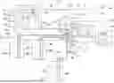
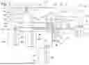


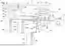
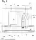
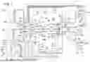
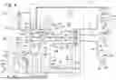


Sources:
- United States Patent and Trademark Office - verify current appl. status at the USPTO↗
Similar patent applications:
- » 20120195793
Clamp mounting for a syringe of a dosing apparatus, dosing apparatus and blood treatment apparatus - » 20190076108
BREAST IMAGING APPARATUS, DOSE CALCULATING APPARATUS, CONTROL METHOD FOR BREAST IMAGING APPARATUS, DOSE CALCULATING METHOD, AND NON-TRANSITORY COMPUTER-READABLE MEDIUM - » 20120193279
Device for guiding a cable in a medical dosing apparatus, dosing device, treatment apparatus, as well as method - » 20140338311
METHOD FOR OPERATING A DOSING APPARATUS AND MOTOR VEHICLE HAVING A DOSING APPARATUS - » 20260042555
DOSING APPARATUS FOR PHARMACEUTICAL PURPOSES AND METHOD FOR OPERATING A DOSING APPARATUS - » 20160302758
Dose calculation apparatus, dose management system, method for controlling these apparatus and system, and recording medium - » 20110213562
Fluorescent agent concentration measuring apparatus, dose control apparatus, administration system, fluorescent agent concentration measuring method, and dose control method - » 20060188402
Fluorescent agent concentration measuring apparatus, dose control apparatus, administration system, fluorescent agent concentration measuring method, and dose control method - » 20080058771
Method for multiple dosage of liquid products, dosing apparatus and dosing system - » 20250224419
DOSING APPARATUS AND DOSING SYSTEM INCLUDING THE SAME
Recent applications in this class:
- » 20260132563 2026-05-14
TUB RING FOR A LAUNDRY WASHING MACHINE - » 20260103832 2026-04-16
BOX VALVES WITH ARRESTORS AND BACKFLOW PREVENTION - » 20260043187 2026-02-12
WATER INLET SYSTEM OF WASHING MACHINE AND WASHING MACHINE - » 20250369175 2025-12-04
WATER SUPPLY AND DRAIN BOX FOR WASHING MACHINE - » 20250320653 2025-10-16
WASHING MACHINE APPLIANCE AND STEAM-GENERATING FEATURES FOR THE SAME - » 20250290246 2025-09-18
Portable stain removal device and method for locally removing a stain from a textile - » 20250230601 2025-07-17
DISPENSING ASSEMBLY FOR AN APPLIANCE USING A SINGLE MOTOR TO DRIVE MULTIPLE ITEMS - » 20250188666 2025-06-12
WASHING SYSTEM - » 20250146208 2025-05-08
CLOTHING PROCESSING APPARATUS AND METHOD FOR CONTROLLING CLOTHING PROCESSING APPARATUS - » 20250129538 2025-04-24
WATER JET SYSTEM FOR A WASHING MACHINE APPLIANCE