CLOTHES TREATING APPARATUS AND METHOD OF CONTROLLING THE CLOTHES TREATING APPARATUS
US20260185294A1
2026-07-02
19/406,182
2025-12-02
Smart Summary: A new clothes treating machine is designed to dry laundry effectively. Inside the machine, there is a tub and a drum that holds the clothes, along with a heater that warms the air and a fan that blows this warm air into the tub. It has a humidity sensor that checks the moisture level of the air being released. If the sensor detects an issue, the machine can stop the drying process based on the weight of the laundry. When everything is working normally, the drying cycle will end based on the humidity level detected by the sensor. 🚀 TL;DR
Abstract:
A clothes treating apparatus is provided. The clothes treating apparatus includes a housing, a tub provided inside the housing, a drum provided inside the tub and configured to accommodate laundry, a heater configured to heat air, a fan configured to blow air heated by the heater to inside of the tub, a discharge device including a discharge flow path through which air discharged from the tub is guided to outside of the housing, a humidity sensor provided on the discharge flow path, memory, including one or more storage media, storing instructions, and at least one processor communicatively coupled to the heater, the fan, the discharge device, the humidity sensor and the memory, wherein the instructions, when executed by the at least one processor individually or collectively, cause the clothes treating apparatus to perform a drying cycle by operating the heater and the fan, according to the humidity sensor being identified as abnormal during the drying cycle, terminate the drying cycle based on a weight of the laundry accommodated in the drum, and, according to the humidity sensor being identified as normal during the drying cycle, terminate the drying cycle based on a humidity value detected by the humidity sensor.
Inventors:
- Dongyoung Kim 16 🇰🇷 Suwon-si, South Korea
- Hyungwoo LEE 25 🇰🇷 Suwon-si, South Korea
- Sangyun BAE 2 🇰🇷 Suwon-si, South Korea
- Seungwan YOO 9 🇰🇷 Suwon-si, South Korea
- Jeehoon KIM 10 🇰🇷 Suwon-si, South Korea
- Myungwoo Lee 20 🇰🇷 Suwon-si, South Korea
- Hyunseok BAE 2 🇰🇷 Suwon-si, South Korea
Applicant:
Interested in similar patents?
Get notified when new applications in this technology area are published.
Classification:
D06F58/38 » CPC main
Domestic laundry dryers; Control of operations performed in domestic laundry dryers characterised by the purpose or target of the control; Control of operational steps, e.g. for optimisation or improvement of operational steps depending on the condition of the laundry of drying, e.g. to achieve the target humidity
D06F58/22 » CPC further
Domestic laundry dryers; General details of domestic laundry dryers Lint collecting arrangements
D06F58/26 » CPC further
Domestic laundry dryers; General details of domestic laundry dryers Heating arrangements, e.g. gas heating equipment
D06F58/50 » CPC further
Domestic laundry dryers; Control of operations performed in domestic laundry dryers characterised by the purpose or target of the control Responding to irregular working conditions, e.g. malfunctioning of blowers
D06F2103/04 » CPC further
Parameters monitored or detected for the control of domestic laundry washing machines, washer-dryers or laundry dryers; Characteristics of laundry or load Quantity, e.g. weight or variation of weight
D06F2103/08 » CPC further
Parameters monitored or detected for the control of domestic laundry washing machines, washer-dryers or laundry dryers; Characteristics of laundry or load Humidity
D06F2105/58 » CPC further
Systems or parameters controlled or affected by the control systems of washing machines, washer-dryers or laundry dryers Indications or alarms to the control system or to the user
D06F2105/62 » CPC further
Systems or parameters controlled or affected by the control systems of washing machines, washer-dryers or laundry dryers Stopping or disabling machine operation
Description
CROSS-REFERENCE TO RELATED APPLICATION(S)
This application is a continuation application, claiming priority under 35 U.S.C. § 365(c), of an International application No. PCT/KR2025/095693, filed on Nov. 4, 2025, which is based on and claims the benefit of a Korean patent application number 10-2024-0202835, filed on Dec. 31, 2024, in the Korean Intellectual Property Office, the disclosure of which is incorporated by reference herein in its entirety.
BACKGROUND
1. Field
The disclosure relates to a clothes treating apparatus including a dryer.
2. Description of Related Art
A clothes treating apparatus is an apparatus for treating and/or managing clothes. The clothes treating apparatus includes a washing machine and a dryer. The washing machine includes a washing machine with a drying function.
The washing machine with the drying function performs washing through friction by stirring laundry, water, and a detergent put into the tub with a driving force from a driving motor.
Cycles performed by the washing machine with the drying function include a washing cycle of supplying a detergent and water to the tub accommodating laundry and washing the laundry while rotating the drum, a rinsing cycle of supplying water to the tub and rinsing the laundry by rotating the drum, and a dehydrating cycle of discharging water from the tub and removing water from the laundry by rotating the drum.
The cycles performed by the washing machine with the drying function include a drying cycle of blowing hot air generated by a dryer into a space where laundry is accommodated to dry the laundry. The washing machine with the drying function includes the dryer for performing the drying cycle.
The above information is presented as background information only to assist with an understanding of the disclosure. No determination has been made, and no assertion is made, as to whether any of the above might be applicable as prior art with regard to the disclosure.
SUMMARY
Aspects of the disclosure are to address at least the above-mentioned problems and/or disadvantages and to provide at least the advantages described below. Accordingly, an aspect of the disclosure is to provide a clothes treating apparatus including a humidity sensor provided on a discharge flow path and a control method of the clothes treating apparatus.
Another aspect of the disclosure is to provide a clothes treating apparatus for identifying abnormality of a humidity sensor and coping with the abnormality and a control method of the clothes treating apparatus.
Another aspect of the disclosure is to provide a clothes treating apparatus for identifying a type of abnormality of a humidity sensor and a control method of the clothes treating apparatus.
Additional aspects will be set forth in part in the description which follows and, in part, will be apparent from the description, or may be learned by practice of the presented embodiments.
In accordance with an aspect of the disclosure, a clothes treating apparatus is provided. The clothes treating apparatus includes a housing, a tub within the housing, a drum within the tub and configured to accommodate laundry, a heater configured to heat air, a fan configured to blow air heated by the heater to inside of the tub, a discharge device including a discharge flow path through which air discharged from the tub is guided to outside of the housing, a humidity sensor provided on the discharge flow path, memory, including one or more storage media, storing instructions and at least one processor communicatively coupled to the heater, the fan, the discharge device, the humidity sensor and the memory, wherein the instructions, when executed by the at least one processor individually or collectively, cause the clothes treating apparatus to perform a drying cycle by operating the heater and the fan, according to the humidity sensor being identified as abnormal during the drying cycle, terminate the drying cycle based on a weight of the laundry accommodated in the drum, and, according to the humidity sensor being identified as normal during the drying cycle, terminate the drying cycle based on a humidity value detected by the humidity sensor.
In accordance with another aspect of the disclosure, a method of controlling a clothes treating apparatus is provided. The method includes performing a drying cycle by operating the heater and the fan, according to the humidity sensor being identified as abnormal during the drying cycle, terminating the drying cycle based on a weight of laundry accommodated in the drum, and according to the humidity sensor being not identified as abnormal during the drying cycle, terminating the drying cycle based on a humidity value detected by the humidity sensor.
In accordance with another aspect of the disclosure, One or more non-transitory computer-readable storage media storing one or more computer programs including computer-executable instruction that, when executed by one or more processors of a clothes treating apparatus individually or collectively, cause the clothes treating apparatus to perform operations, the clothes treating apparatus including a housing, a tub within the housing, a drum within the tub and configured to accommodate laundry, a heater configured to heat air, a fan configured to blow air heated by the heater to inside of the tub, a discharge device including a discharge flow path through which air discharged from the tub is guided to outside of the housing, and a humidity sensor provided on the discharge flow path are provided. The operations include performing a drying cycle by operating the heater and the fan, according to the humidity sensor being identified as abnormal during the drying cycle, terminating the drying cycle based on a weight of the laundry accommodated in the drum, and according to the humidity sensor being not identified as abnormal during the drying cycle, terminating the drying cycle based on a humidity value detected by the humidity sensor.
Other aspects, advantages, and salient features of the disclosure will become apparent to those skilled in the art from the following detailed description, which, taken in conjunction with the annexed drawings, discloses various embodiments of the disclosure.
DESCRIPTION OF DRAWINGS
The above and other aspects, features, and advantages of certain embodiments of the disclosure will be more apparent from the following description taken in conjunction with the accompanying drawings, in which:
FIG. 1 illustrates a clothes treating apparatus according to an embodiment of the disclosure;
FIG. 2 illustrates a clothes treating apparatus in a different direction from that shown in FIG. 1 according to an embodiment of the disclosure;
FIG. 3 illustrates a cross section of a clothes treating apparatus according to an embodiment of the disclosure;
FIG. 4 illustrates some of internal components of a clothes treating apparatus according to an embodiment of the disclosure;
FIG. 5 illustrates some of internal components of a clothes treating apparatus in a different direction from that shown in FIG. 4 according to an embodiment of the disclosure;
FIG. 6 illustrates a dryer of a clothes treating apparatus, separated from a tub, according to an embodiment of the disclosure;
FIG. 7 illustrates a dryer of a clothes treating apparatus, separated from a tub, in a different direction from that shown in FIG. 6 according to an embodiment of the disclosure;
FIG. 8 illustrates a hot air supply device and a discharging device of a dryer of a clothes treating apparatus, disassembled from a drying case, according to an embodiment of the disclosure;
FIG. 9 illustrates insides of a hot air supply device and a discharging device by disassembling some components of a dryer of a clothes treating apparatus according to an embodiment of the disclosure;
FIG. 10 illustrates insides of a hot air supply device and a discharging device by disassembling some components of a dryer of a clothes treating apparatus in a different direction from that shown in FIG. 9 according to an embodiment of the disclosure;
FIG. 11 is a control block diagram of a clothes treating apparatus according to an embodiment of the disclosure;
FIG. 12 is a flowchart illustrating a control method of a clothes treating apparatus according to an embodiment of the disclosure;
FIG. 13 is a flowchart illustrating a process of detecting a failure of a heater in a control method of a clothes treating apparatus according to an embodiment of the disclosure;
FIG. 14 is a flowchart illustrating a process of terminating a drying cycle based on a humidity sensor in a control method of a clothes treating apparatus according to an embodiment of the disclosure;
FIG. 15 illustrates a guide interface according to an embodiment of the disclosure; and
FIG. 16 is a flowchart illustrating a process of terminating a drying cycle based on a weight of laundry in a control method of a clothes treating apparatus according to an embodiment of the disclosure.
The same reference numerals are used to represent the same elements throughout the drawings.
MODES OF THE INVENTION
The following description with reference to the accompanying drawings is provided to assist in a comprehensive understanding of various embodiments of the disclosure as defined by the claims and their equivalents. It includes various specific details to assist in that understanding but these are to be regarded as merely exemplary. Accordingly, those of ordinary skill in the art will recognize that various changes and modifications of the various embodiments described herein can be made without departing from the scope and spirit of the disclosure. In addition, descriptions of well-known functions and constructions may be omitted for clarity and conciseness.
The terms and words used in the following description and claims are not limited to the bibliographical meanings, but, are merely used by the inventor to enable a clear and consistent understanding of the disclosure. Accordingly, it should be apparent to those skilled in the art that the following description of various embodiments of the disclosure is provided for illustration purpose only and not for the purpose of limiting the disclosure as defined by the appended claims and their equivalents.
It is to be understood that the singular forms “a,” “an,” and “the” include plural referents unless the context clearly dictates otherwise. Thus, for example, reference to “a component surface” includes reference to one or more of such surfaces.
As used herein, each of the expressions “A or B,” “at least one of A and B,” “at least one of A or B,” “A, B, or C,” “at least one of A, B, and C,” and “at least one of A, B, or C,” may include one or all possible combinations of the items listed together with a corresponding expression among the expressions.
The term “and/or” includes any and all combinations of one or more of a plurality of associated listed items.
As used herein, such terms as “1st” and “2nd” or “first” and “second” may be used to simply distinguish a corresponding component from another, and does not limit the components in other aspect (for example, importance or order).
It is to be understood that if a certain component (for example, a first component) is referred to, with or without the term “operatively” or “communicatively”, as “coupled with,” “coupled to,” “connected with,” or “connected to” another component (for example, a second component), it means that the component may be coupled with the other component directly (for example, wiredly), wirelessly, or via a third element.
It is to be understood that the terms, such as “including” or “having,” or the like, are intended to indicate the existence of the features, numbers, steps, operations, components, parts, or combinations thereof disclosed in the specification, and are not intended to preclude the possibility that one or more other features, numbers, steps, operations, components, parts, or combinations thereof may exist or may be added.
It is to be understood that if a certain component is referred to as being “coupled with,” “coupled to,” “supported on” or “in contact with” another component, it means that the component may be coupled with the other component directly or indirectly via a third component.
It will also be understood that when a certain component is referred to as being “on” or “over” another component, it can be directly on the other component or intervening components may also be present.
A washing machine according to various embodiments may perform a washing cycle, a rinsing cycle, a dehydrating cycle, and a drying cycle. The washing machine may be an example of a clothes treating apparatus and may be a concept including an apparatus for washing clothes (an object to be washed or an object to be dried), an apparatus for drying clothes, and an apparatus capable of performing both washing and drying of clothes.
The washing machine according to various embodiments may include a top-loading washing machine, wherein an inlet through which laundry is put into or taken out of the top-loading washing machine opens upward, or a front-loading washing machine, wherein a laundry inlet opens in a front direction. The washing machine according to various embodiments may include another loading type of washing machine other than the top-loading washing machine and the front-loading washing machine.
The top-loading washing machine may wash laundry with water streams generated by a rotating body, such as a pulsator. The front-loading washing machine may wash laundry by rotating a drum to repeatedly raise and drop the laundry. The front-loading washing machine may include a washing machine with a drying function which is capable of drying laundry accommodated in a drum. The washing machine with the drying function may include a hot air supply device for supplying hot air into the drum. For example, the washing machine with the drying function may include a heater. The washing machine according to various embodiments may include a washing machine using another washing method other than the above-described washing methods.
The washing machine according to various embodiments may include a housing that accommodates various kinds of components therein. The housing may be provided in a shape of a box having a laundry inlet at one side.
The washing machine may include a door that opens or closes the laundry inlet. The door may be rotatably mounted on the housing by a hinge. At least one portion of the door may be transparent or translucent to show inside of the housing.
The washing machine may include a tub within the housing to store water. The tub may be substantially in a shape of a cylinder in which a tub opening is formed at one side, and the tub may be positioned inside the housing, wherein the tub opening is positioned to correspond to the laundry inlet.
The tub may be connected to the housing by a damper. The damper may absorb vibrations generated according to rotations of a drum to attenuate vibrations that are transferred to the housing.
The washing machine may include the drum that accommodates laundry.
The drum may be positioned inside the tub, wherein a drum opening provided at one side of the drum corresponds to the laundry inlet and the tub opening. Laundry may pass through the laundry inlet, the tub opening, and the drum opening sequentially to be accommodated in the drum or taken out of the drum.
The drum may perform operations according to a washing cycle, a rinsing cycle, and/or a dehydrating cycle, while rotating inside the tub. A plurality of through holes may be formed in a cylindrical wall of the drum such that water stored in the tub enters inside of the drum or is discharged out of the drum.
The washing machine may include a driver for rotating the drum. The driver may include a driving motor, and a rotating shaft for transferring a driving force generated in the driving motor to the drum. The rotating shaft may be connected to the drum by penetrating the tub.
The driver may perform operations according to a washing cycle, a rinsing cycle and/or a dehydrating cycle, or a drying cycle by rotating the drum forward or backward.
The washing machine may include a water supply for supplying water to the tub. The water supply may include a water supply tube, and a water supply valve provided in the water supply tube. The water supply tube may be connected to an external water supply source. The water supply tube may extend to a detergent supply device and/or the tub from the external water supply source. Water may be supplied to the tub via the detergent supply device. Water may be supplied to the tub not via the detergent supply device.
The water supply valve may open or close the water supply tube in response to an electrical signal from a controller. The water supply valve may allow or block supply of water from the external water supply source to the tub. The water supply valve may include, for example, a solenoid valve that is opened or closed in response to an electrical signal.
The washing machine may include the detergent supply device configured to supply a detergent to the tub. The detergent supply device may include a manual detergent supply device into which a user needs to put a detergent to be used whenever performing washing, and an automatic detergent supply device which stores a large amount of detergent and automatically puts a preset amount of detergent upon washing. The detergent supply device may include a detergent case for storing a detergent. The detergent supply device may supply a detergent into the inside of the tub while water is supplied. Water supplied through the water supply tube may be mixed with a detergent via the detergent supply device. The water mixed with the detergent may be supplied to the inside of the tub. The detergent may include a detergent for pre-washing, a detergent for main washing, a fabric softener, bleach, or the like, and the detergent case may be partitioned into a pre-washing detergent storage area, a main washing detergent storage area, a fabric softener storage area, and a bleach storage area.
The washing machine may include a drain device for discharging water accommodated in the tub to outside. The drain device may include a drain tube extending from a lower portion of the tub to outside of the housing, a drain valve provided in the drain tube and configured to open or close the drain tube, and a pump provided on the drain tube. The pump may pump water of the drain tube to the outside of the housing.
The washing machine may include a control panel positioned on one side of the housing. The control panel may include a user interface that enables a user to interact with the washing machine. The user interface may include at least one input interface and at least one output interface.
The at least one input interface may convert sensory information received from a user into an electrical signal.
The at least one input interface may include a power button, an operation button, a course selection dial (or a course selection button), and a washing/rinsing/dehydrating setting button. The at least one input interface may include, for example, a tact switch, a push switch, a slide switch, a toggle switch, a micro switch, a touch switch, a touch pad, a touch screen, a jog dial, and/or a microphone, or the like.
The at least one output interface may visually or aurally transfer information related to an operation of the washing machine to a user.
For example, the at least one output interface may transfer information related to a washing course and an operation time of the washing machine or a washing setting/rinsing setting/dehydrating setting to a user. Information related to an operation of the washing machine may be output through a screen, an indicator, a voice, or the like. The at least one output interface may include, for example, a liquid crystal display (LCD) panel, a light emitting diode (LED) panel, a speaker, or the like.
The washing machine may include a communication module for communicating with an external device by wire and/or wirelessly.
The communication module may include at least one of a short-range communication module or a long-distance communication module.
The communication module may transmit data to an external device (for example, a server, a user device, and/or another home appliance) or receive data from the external device. For example, the communication module may establish communication with a server and/or a user device and/or another home appliance to transmit/receive various data.
To this end, the communication module may establish a direct (for example, wired) communication channel or a wireless communication channel with the external device, and support communication through the established communication channel. According to an embodiment of the disclosure, the communication module may include a wireless communication module (for example, a cellular communication module, a short-range communication module, or a global navigation satellite system (GNSS) communication module) or a wired communication module (for example., a local area network (LAN) communication module or a power line communication module). A corresponding communication module among the communication modules may communicate with the external device through a first network (for example, a short-range communication network, such as Bluetooth, wireless fidelity (Wi-Fi) Direct, or Infrared data association (IrDA)) or a second network (for example, a long-distance communication network, such as a legacy cellular network, a 5th generation (5G) network, a next-generation communication network, the Internet, or a computer network (for example, a LAN or a wide area network (WAN)). The various kinds of communication modules may be integrated into a single component (for example, a single chip) or implemented with a plurality of components (for example, a plurality of chips).
The short-range wireless communication module may include a Bluetooth communication module, a Bluetooth low energy (BLE) communication module, a near field communication (NFC) communication module, a wireless local area network (WLAN, Wi-Fi) communication module, a Zigbee communication module, an IrDA communication module, a Wi-Fi direct (WFD) communication module, a ultrawideband (UWB) communication module, an Ant+ communication module, a microwave (uWave) communication module, or the like, although not limited thereto.
The long-distance wireless communication module may include a communication module that performs various kinds of long-distance communications, and may include a mobile communication device. The mobile communication device may transmit/receive a wireless signal to/from at least one of a base station, an external terminal, or a server on a mobile communication network.
According to an embodiment of the disclosure, the communication module may communicate with an external device, such as a server, a user device, another home appliance, or the like, through a surrounding application processor (AP). The AP may connect a LAN to which the washing machine or a user device is connected to a WAN to which a server is connected. The washing machine or the user device may be connected to the server through the WAN. A controller may control various components (for example, the driving motor and the water supply valve) of the washing machine. The controller may control various components of the washing machine to perform at least one cycle including water supply, washing, rinsing, and/or dehydrating, or the like, according to a user input. For example, the controller may control the driving motor to adjust a rotational speed of the drum or control the water supply valve of the water supply to supply water to the tub.
The controller may include hardware, such as a central processing unit (CPU) or memory, and software, such as a control program. For example, the controller may include at least one memory that stores data in the form of an algorithm or program for controlling operations of components in the washing machine, and at least one processor that performs the above-described operations by using data stored in the at least one memory. The memory and the processor may be implemented with separate chips. The processor may include one, two, or more processor chips or one, two, or more processing cores. The memory may include one, two, or more memory chips or one, two, or more memory blocks. In addition, the memory and the processor may be implemented with a single chip.
Hereinafter, a clothes treating apparatus according to various embodiments will be described in detail with reference to the accompanying drawings. Hereinafter, a washing machine with a drying function will be described as an example of the clothes treating apparatus. However, a concept of the disclosure is not limited to the washing machine with the drying function and may be applied to various apparatuses for processing and/or managing clothes.
In the following description, the terms “front”, “rear”, “left”, “right”, “upper”, or the like, are defined based on the drawings, and the shapes and positions of the components are not limited by the terms.
For example, an X-axis direction may be defined as a front-rear direction, an Y-axis direction may be defined as a left-right direction, and a Z-axis direction may be defined as an up-down direction.
It should be appreciated that the blocks in each flowchart and combinations of the flowcharts may be performed by one or more computer programs which include computer-executable instructions. The entirety of the one or more computer programs may be stored in a single memory device or the one or more computer programs may be divided with different portions stored in different multiple memory devices.
Any of the functions or operations described herein can be processed by one processor or a combination of processors. The one processor or the combination of processors is circuitry performing processing and includes circuitry like an application processor (AP, e.g., a central processing unit (CPU)), a communication processor (CP, e.g., a modem), a graphical processing unit (GPU), a neural processing unit (NPU) (e.g., an artificial intelligence (AI) chip), a wireless-fidelity (Wi-Fi) chip, a Bluetooth™ chip, a global positioning system (GPS) chip, a near field communication (NFC) chip, connectivity chips, a sensor controller, a touch controller, a finger-print sensor controller, a display drive integrated circuit (IC), an audio CODEC chip, a universal serial bus (USB) controller, a camera controller, an image processing IC, a microprocessor unit (MPU), a system on chip (SoC), an IC, or the like.
FIG. 1 illustrates a clothes treating apparatus according to an embodiment of the disclosure.
FIG. 2 illustrates a clothes treating apparatus in a different direction from that shown in FIG. 1 according to an embodiment of the disclosure.
FIG. 3 illustrates a cross section of a clothes treating apparatus according to an embodiment of the disclosure.
FIG. 4 illustrates some of internal components of a clothes treating apparatus according to an embodiment of the disclosure.
FIG. 5 illustrates some of internal components of a clothes treating apparatus in a different direction from that shown in FIG. 4 according to an embodiment of the disclosure.
Referring to FIGS. 1, 2, 3, 4, and 5, a clothes treating apparatus 1 according to various embodiments may include a housing 10 that accommodates various components therein. The housing 10 may be provided in a shape of a box having a laundry inlet 11 at one side. The laundry inlet 11 may open substantially in a front direction.
The clothes treating apparatus 1 may include a laundry door 17 that opens or closes the laundry inlet 11. The laundry door 17 may be rotatably mounted on the housing 10 by a hinge. At least one portion of the laundry door 17 may be transparent or translucent to show inside of the housing 10. For example, the laundry door 17 may include tempered glass.
The clothes treating apparatus 1 may include a lower door 18 for allowing an access to a lower detergent supply device 60. The clothes treating apparatus 1 may include an upper door 19 for allowing an access to an upper detergent supply device 50 and a discharge filter 150.
The clothes treating apparatus 1 may include a tub 20 within the housing 10 to store water. The tub 20 may be provided in a substantially cylindrical shape having a tub opening 21 at one side, wherein the tub opening 21 may be positioned inside the housing 10 in correspondence to the laundry inlet 11. The tub opening 21 may open substantially in the front direction.
The tub 20 may be connected to the housing 10 by a damper 25. The damper 25 may absorb vibrations generated according to rotations of a drum 30 to attenuate vibrations that are transferred to the housing 10.
The clothes treating apparatus 1 may include a diaphragm 22 for connecting the tub 20 to the housing 10. For example, the diaphragm 22 may extend between the laundry inlet 11 of the housing 10 and the tub opening 21 of the tub 20. The diaphragm 22 may be detachably mounted on the tub opening 21 of the tub 20. The diaphragm 22 may reduce vibrations of the tub 2 transferred to the housing 10. For example, the diaphragm 22 may include a more flexible material than the housing 10 and the tub 20.
The clothes treating apparatus 1 may include the drum 30 that accommodates laundry. On an inner circumferential surface of the drum 30, at least one lifter 33 may be mounted to perform washing by raising and dropping laundry.
The drum 30 may be positioned inside the tub 20 such that the drum opening 31 provided at one side corresponds to the laundry inlet 11 and the tub opening 21. Laundry may be put into or taken out of the drum 30 by passing through the laundry inlet 11, the diaphragm 22, the tub opening 21, and the drum opening 31 sequentially. The drum opening 31 may open substantially in the front direction.
The drum 30 may perform operations according to a washing cycle, a rinsing cycle, and/or a dehydrating cycle, while rotating inside the tub 20. A plurality of through holes 32 may be formed in a cylindrical wall of the drum 30 such that water stored in the tub 20 enters the inside of the drum 30 or is discharged out of the drum 30.
The clothes treating apparatus 1 may include a driver 36 for rotating the drum 30. The driver 36 may include a driving motor and a rotating shaft for transferring a driving force generated in the driving motor to the drum 30. The rotating shaft may be connected to the drum 30 by penetrating the tub 20.
The driver 36 may perform operations according to a washing cycle, a rinsing cycle and/or a dehydrating cycle, or a drying cycle by rotating the drum 30 forward or backward.
The clothes treating apparatus 1 may include a water supply device 40 for supplying water to the tub 20. The water supply device 40 may include water supply valves 41 and 42 capable of being connected to an external water supply source. For example, the water supply valves 41 and 42 may include a first water supply valve 41 and a second water supply valve 42. For example, the water supply valves 41 and 42 may include a hot water valve 41 for supplying hot water, and a cold water valve 42 for supplying cold water.
The water supply device 40 may include water supply tubes 43 and 44. The water supply tubes 43 and 44 may be connected to the water supply valves 41 and 42. For example, the water supply tubes 43 and 44 may include a first water supply tube 43 and a second water supply tube 44. For example, each of the water supply tubes 43 and 44 may be provided as a hose, a pipe, or the like, made of a flexible material.
For example, the water supply tubes 43 and 44 may include a hot water tube 43 connected to the hot water valve 41, and a cold water tube 44 connected to the cold water valve 42. At least one of the water supply tubes 43 and 44 may guide water from the water supply valves 41 and 42 to the tub 20. At least one of the water supply tubes 43 and 44 may extend from the water supply valve 41, 42 to the tub 20. Water may be supplied to the lower detergent supply device 60 via the tub 20. Alternatively, water may be supplied to the lower detergent supply device 60 not via the tub 20.
The water supply valves 41 and 42 may open or close the water supply tubes 43 and 44 in response to an electrical signal from a controller 80 (see FIG. 17). The water supply valves 41 and 42 may allow or block supply of water from the external water supply source to the tub 20. Each of the water supply valves 41 and 42 may include, for example, a solenoid valve that is opened or closed in response to an electrical signal.
The clothes treating apparatus 1 may include detergent supply devices 50 and 60 for supplying a detergent to the tub 20. The detergent supply devices 50 and 60 may include the upper detergent supply device 50 and the lower detergent supply device 60. The detergent may be used as a comprehensive term for a detergent for pre-washing, a detergent for main washing, fabric softener, bleach, or the like.
The upper detergent supply device 50 may be positioned above the tub 20. The upper detergent supply device 50 may be positioned above the tub 20 in an up-down direction. The upper detergent supply device 50 may include a manual detergent supply device into which a user needs to put a detergent to be used whenever performing washing, or an automatic detergent supply device which stores a large amount of detergent and automatically puts a preset amount of detergent upon washing. The upper detergent supply device 50 may be connected to the tub 20 through a detergent connecting tube 51. For example, the upper detergent supply device 50 may supply a solid washing detergent and/or a fabric softener to the tub 20. However, kinds of detergents are not limited to the above-mentioned examples.
The lower detergent supply device 60 may be positioned below the tub 20. The lower detergent supply device 60 may be positioned below the tub 20 in the up-down direction. The lower detergent supply device 60 may include a manual detergent supply device into which a user needs to put a detergent to be used whenever performing washing, or an automatic detergent supply device which stores a large amount of detergent and automatically puts a preset amount of detergent upon washing. For example, the lower detergent supply device 60 may supply a liquid detergent and/or fabric softener to the tub 20. However, kinds of detergents are not limited to the above-mentioned examples.
The clothes treating apparatus 1 may include a drain device 70 for discharging water accommodated in the tub 20 to outside. The drain device 70 may include a drain pump 71 for discharging water of the tub 20 to the outside of the housing 10.
The clothes treating apparatus 1 may include a circulation pump 76 for circulating water of the tub 20 to the tub 20 via the lower detergent supply device 60.
The drain device 70 may be connected to the tub 20 through a tub connection tube 72. The drain device 70 may discharge water of the tub 20 to the outside of the housing 10 through the drain tube 73.
The clothes treating apparatus 1 according to an embodiment of the disclosure may include a washing water heater 24. The washing water heater 24 may be positioned below the tub 20 to heat washing water during washing. Also, the water supply device 40 may supply a preset amount of water to a bottom of the tub 20 through a connection flow path P during a drying cycle, and the washing water heater 24 may generate a steam by heating water supplied to the inside of the tub 20 through the water supply device 40, the connection flow path P, and a tub exhaust port 27. For example, a steam generated by the water supply device 40 and the washing water heater 24 may be in contact with clothes during a drying cycle to smooth out wrinkles of the clothes.
For example, the clothes treating apparatus 1 according to an embodiment of the disclosure, which is a washing machine 1 with a washing function and a drying function, may include the washing water heater 24 for heating washing water, unlike existing dryers, and generate a steam by using the washing water heater 24, the connection flow path P, and the water supply device 40 for washing to smooth out wrinkles of clothes as much as possible during a drying cycle.
The clothes treating apparatus 1 may include a control panel 15 positioned on one side of the housing 10. The control panel 15 may provide a user interface that enables a user to interact with the clothes treating apparatus 1. The user interface may include at least one input interface and at least one output interface.
The at least one input interface may convert sensory information received from a user into an electrical signal.
The at least one input interface may include a power button, an operation button, a course selection dial (or a course selection button), and a washing/rinsing/dehydrating setting button. The at least one input interface may include, for example, a tact switch, a push switch, a slide switch, a toggle switch, a micro switch, a touch switch, a touch pad, a touch screen, a jog dial, and/or a microphone, or the like.
The at least one output interface may visually or aurally transfer information related to an operation of the clothes treating apparatus 1 to a user.
For example, the at least one output interface may transfer information related to a washing course and an operation time of the clothes treating apparatus 1 or a washing setting/rinsing setting/dehydrating setting to a user. Information related to an operation of the clothes treating apparatus 1 may be output through a screen, an indicator, a voice, or the like. The at least one output interface may include, for example, a LCD panel, a LED panel, a speaker, or the like.
The clothes treating apparatus 1 may include a control box 15c for the control panel 15. The control box 15c for the control panel 15 may be electrically connected to the control panel 15. The control box 15c for the control panel 15 may supply power to the control panel 15. The control box 15c for the control panel 15 may process information received through the control panel 15. The control box 15c for the control panel 15 may control the control panel 15 to output information.
The clothes treating apparatus 1 may include a dryer 100 for drying laundry accommodated inside the drum 30. The dryer 100 may heat air and supply the air to the inside of the tub 20. The dryer 100 may discharge air discharged from the tub 20 to the outside of the clothes treating apparatus 1. The clothes treating apparatus 1 may receive outside air, heat the outside air, then supply the outside air to the tub 20 to dry laundry inside the drum 30, and then discharge air dried the laundry inside the drum 30 and then discharged from the tub 20 to the outside of the clothes treating apparatus 1. The dryer 100 according to various embodiments may be positioned above the tub 20.
The clothes treating apparatus 1 may include a terminal module 90. The terminal module 90 may include a terminal block. For example, the clothes treating apparatus 1 with a drying function may use a relatively high voltage and stably supply power through the terminal module 90.
The clothes treating apparatus 1 may include a terminal cover 91 for covering the terminal module 90. The terminal cover 91 may be detachably coupled to the housing 10. For example, the terminal cover 90 may be provided in the dryer 100 and the terminal cover 91 may be detachably mounted on the dryer 100.
The clothes treating apparatus 1 may include a connector coupling portion 149 to which a connector for electrically connecting the terminal module 90 to the control panel 15 is coupled. For example, a connector provided in a wire extending from the terminal module 90 may be connected to a connector provided in a wire extending from the control panel 15 at the connector coupling portion 149. The connector coupling portion 149 may include a space where the connector provided in the wire extending from the terminal module 90 is coupled to the connector provided in the wire extending from the control panel 15. For example, the connector coupling portion 149 may be provided in the dryer 100. For example, the connector coupling portion 149 may be provided in a discharge cover 142 of a discharge device 140 of the dryer 100.
FIG. 6 illustrates a dryer of a clothes treating apparatus, separated from a tub, according to an embodiment of the disclosure.
FIG. 7 illustrates a dryer of a clothes treating apparatus, separated from a tub, in a different direction from that shown in FIG. 6 according to an embodiment of the disclosure.
FIG. 8 illustrates a hot air supply device and a discharging device of a dryer of a clothes treating apparatus, disassembled from a drying case, according to an embodiment of the disclosure.
FIG. 9 illustrates insides of a hot air supply device and a discharging device by disassembling some components of a dryer of a clothes treating apparatus according to an embodiment of the disclosure.
FIG. 10 illustrates insides of a hot air supply device and a discharging device by disassembling some components of a dryer of a clothes treating apparatus in a different direction from that shown in FIG. 9 according to an embodiment of the disclosure.
Referring to FIGS. 4, 5, 6, 7, 8, 9, and 10, the dryer 100 may include a drying case 101. Various components of the dryer 100 may be installed in the drying case 101. For example, a hot air supply device 110 and/or the discharge device 140 of the dryer 100 may be installed in the drying case 101. The dryer 100 may be provided as one module by installing the hot air supply device 110 and the discharge device 140 in the drying case 101.
Referring to FIG. 8, the drying case 101 may include a case opening 101a through which air entered the inside of the housing 10 flows into inside of the dryer 100. For example, the case opening 101a may include at least one opening. For example, the case opening 101a may be provided at a side portion of the drying case 101 adjacent to a fan 130.
Referring to FIG. 8, the drying case 101 may include a guide installing portion 102 through which inside air of the dryer 100 is discharged to outside of the dryer 100. By installing a portion of the discharge device 140 at the guide installing portion 102, inside air of the dryer 100 may be discharged to the outside of the dryer 100. For example, the guide installing portion 102 may be provided at a rear side portion of the drying case 101.
The dryer 100 may include a reinforcing frame 109 for reinforcing rigidity of the drying case 101. For example, the reinforcing frame 109 may be detachably mounted on a front end portion of the drying case 101. For example, after the hot air supply device 110 and the discharge device 140 are installed in the drying case 101, the reinforcing frame 109 may be mounted on the drying case 101. For example, after the reinforcing frame 109 is separated from the drying case 101, the hot air supply device 110 and the discharge device 140 may be separated from the drying case 101.
The dryer 100 may include the hot air supply device 110 for supplying hot air, that is, heated air to the tub 20. The hot air supply device 110 may be mounted on the drying case 101. Inside the hot air supply device 110, a supply flow path 116 through which air to be supplied to the tub 20 flows may be formed.
For example, the hot air supply device 110 may be connected to the diaphragm 22. An end of the hot air supply device 110, through which air is discharged, may be connected to the diaphragm 22. The diaphragm 22 may include a diaphragm connecting portion 22a connected to the end of the hot air supply device 110. The diaphragm connecting portion 22a may be provided with an air inlet 26. Air discharged from the hot air supply device 110 may be supplied to the inside of the drum 30 through the air inlet 26.
The hot air supply device 110 may guide air entered the inside of the housing 10 to the tub 20. The hot air supply device 110 may heat air entered the inside of the housing 10. The hot air supply device 110 may change outside air entered the inside of the housing to hot and dry air.
For example, referring to FIG. 2, an outside air hole 10a for receiving outside air may be formed in a rear side of the housing 10, and while the hot air supply device 110 operates, outside air may enter the inside of the housing 10 through the outside air hole 10a. Referring to FIG. 8, air entered the inside of the housing 10 may flow into the dryer 100 through at least one case opening 101a formed in the drying case 101. The air flowed into the inside of the dryer 100 may flow into the hot air supply device 110.
The hot air supply device 110 may include a supply base 111. The supply base 111 may be mounted on the drying case 101. The supply base 111 may form a part of the supply flow path 116. Components of the hot air supply device 110 may be accommodated in the supply base 111. The supply base 111 may form at least a part of the supply flow path 116. For example, an upper side of the supply base 111 may open.
The hot air supply device 110 may include a supply cover 112. The supply cover 112 may be coupled to the supply base 111. The supply cover 112 may cover the open side of the supply base 111. The supply cover 112 may form at least a part of the supply flow path 116 together with the supply base 111. For example, according to the supply cover 112 being coupled to the supply base 111, at least a part of the supply flow path 116 may be formed.
The hot air supply device 110 may include a heater 120 for heating air passing through the hot air supply device 110. The heater 120 may heat air passing through the supply flow path 116. For example, the heater 120 may include a dual heater.
The dryer 100 may include a heater control box 129 for controlling the heater 120. The heater control box 129 may be electrically connected to the heater 120. For example, the heater control box 129 may be mounted on the drying case 101.
The hot air supply device 110 may include the fan 130 for forming an air current inside the hot air supply device 110. The fan 130 may suck in outside air of the housing 10 and blow the air to the tub 20. The fan 130 may supply air to an object inside the drum 30. For example, the fan 130 may include a sirocco fan. For example, the fan 130 may suck in air in a direction of a rotating shaft of the fan 130 and discharge the air outward from a circumference of the fan 130.
The hot air supply device 110 may include a fan driver 135 for providing power to the fan 130. For example, the hot air supply device 110 may include a fan cover 113 that is couplable to the supply base 111 and/or the supply cover 112. The fan driver 135 may be installed in the fan cover 113.
Referring to FIG. 10, the supply base 111 may include a supply inlet 117 through which air flows into the hot air supply device 110. The supply inlet 117 may be formed by penetrating the supply base 111 in the direction of the rotating shaft of the fan 130. While the fan 130 operates, outside air of the hot air supply device 110 may flow into the hot air supply device 110 through the supply inlet 117.
The hot air supply device 110 may include a supply connection part 114 connected to the tub 20. The supply connection part 114 may be connected to a front end portion of the tub 20. For example, the supply base 111 may extend in a front-rear direction, and the supply connection part 114 may extend in the up-down direction.
The supply connection part 114 may include a supply guide portion 114a for guiding air flowing from the supply base 111 to the supply connection part 114. The supply guide portion 114a may have a rib shape. The supply guide portion 114a may stir dry air that is supplied to the tub 20 to reduce a temperature deviation of the dry air that is supplied to the tub 20.
For example, the supply connection part 114 may be positioned at an end of the supply base 111, which is opposite to another end of the supply base 111 at which the fan 130 is positioned. For example, the supply connection part 114 may be connected to one end of the supply base 111, which is opposite to another end of the supply base 111 at which the supply inlet 117 is formed. Because the supply connection part 14 and the supply inlet 117 are positioned at both ends of the supply base 111 in such a way as to be spaced from each other, air flowing in through the supply inlet 117 may be given a time to be heated by the heater 120 before being supplied to the tub 20 through the supply connection part 114.
The supply connection part 114 of the hot air supply device 110 may be connected to the air inlet 26. The air inlet 26 of the tub 20 may be provided at the diaphragm 22 provided in the front end portion of the tub 20. The supply connection part 114 may be connected to the diaphragm connecting portion 22a provided in the diaphragm 22. For example, the supply connection part 114 may be fixed to the diaphragm connection portion 22a by installing a clamp at an area at which the supply connection part 114 is coupled to the diaphragm connecting portion 22a.
The dryer 100 may include a thermostat 170 configured to stop the dryer 100 when a temperature of dry air supplied through the hot air supply device 110 exceeds a preset temperature. For example, the thermostat 170 may be mounted on the hot air supply device 110. For example, the thermostat 170 may include a sensor for detecting a temperature of the supply flow path 116.
Referring to FIGS. 3 to 7, air heated by the dryer 100 may be supplied to the inside of the drum 30 through the tub 20. To ensure a time for which the heated air supplied to the inside of the drum 30 removes water of laundry, a tub exhaust port 27 may be opposite to the air inlet 26 through which air heated by the dryer 100 is supplied to the tub 20. To cause heated air to come in more contact with laundry by increasing a distance by which the heated air flows inside the drum 30 and/or a time for which the heated air flows inside the drum 30, the tub exhaust port 27 may be positioned to be opposite to the air inlet 26 through which air heated by the dryer 100 is supplied to the tub 20. By increasing a time for which heated air comes in contact with laundry, drying efficiency may be improved.
The air inlet 26 and the tub exhaust port 27 according to an embodiment of the disclosure may be arranged to maximize use of heated air provided from the dryer 100. For example, the air inlet 26 may be positioned in the front end portion of the tub 20, and the tub exhaust port 27 may be positioned in a rear end portion of the tub 20.
The clothes treating apparatus 1 according to various embodiments may include the connection flow path P through which air discharged from the tub 20 flows to the dryer 100. The connection flow path P may allow air discharged from the tub exhaust port 27 to flow to a discharge flow path 146 of the dryer 100. The connection flow path P may discharge humid air passed through the tub 20. For example, the connection flow path P may be provided behind the tub 20.
Internal air of the tub 20 may be discharged to a tub duct 28 through the tub exhaust port 27 formed in a rear side of the tub 20. The air discharged to the tub duct 28 may flow along the connection flow path P and be supplied to the dryer 100.
The clothes treating apparatus 1 according to various embodiments may include the tub duct 28 that forms at least a part of the connection flow path P. For example, the tub duct 28 may be integrated into the tub 20. For example, the tub 20 may include the tub duct 28. The tub duct 28 may surround the tub exhaust port 27.
The clothes treating apparatus 1 according to various embodiments may include a duct cover 29 that forms at least a part of the connection flow path P. The duct cover 29 may cover an open rear side of the tub duct 28. For example, the tub 20 may include the duct cover 29. The duct cover 29 may form at least a part of the connection flow path P through which air discharged through the tub exhaust port 27 flows into the dryer 100.
In the clothes treating apparatus 1 according to various embodiments of the disclosure, the connection flow path P may be formed by coupling the duct cover 29 to the tub duct 28.
The tub duct 28 according to an embodiment of the disclosure may include a recess portion 28a that forms a part of the connection flow path P through which air discharged from the tub 20 flows. A reinforcement rib 23 for reinforcing rigidity of the tub 20 may be provided on a rear surface of the tub 20, and the recess portion 28a may be provided as a portion sunken from an end of the reinforcement rib 23 protruding from the rear surface of the tub 20. The recess portion 28a may be provided as a portion of the rear surface of the tub 20, on which the reinforcement rib 23 is not formed. The tub exhaust port 27 through which air is discharged from the tub 20 may be formed in the recess portion 28a. The tub duct 28 may include a partition rib 28d that extends along a circumference of the recess portion 28a. The partition rib 28d may partition an area on which the recess portion 28a is formed from an area on which the reinforcement rib 23 is formed, on the rear surface of the tub 20.
The tub duct 28 according to an embodiment of the disclosure may include a duct connecting portion 28b that forms another part of the connection flow path P through which air passed through the recess portion 28a flows. The duct connecting portion 28b may protrude outward from an outer circumferential surface of the tub 20. The duct connecting portion 28b may protrude substantially upward from the outer circumferential surface of the tub 20.
The duct connecting portion 28b may allow the recess portion 28a to communicate with the dryer 100. The duct connecting portion 28b may be connected to the discharge connection part 143 of the dryer 100. The duct connecting portion 28b may form a passage forming the connection flow path P together with the recess portion 28a and the duct cover 29.
The duct connecting portion 28b may be covered by the duct cover 29. One side of the duct connecting portion 28b may open. The duct cover 29 may cover the open side of the duct connecting portion 28b.
The duct cover 29 may cover both the recess portion 28a and the duct connecting portion 28b. For example, the duct cover 29 may cover both the open side of the recess portion 28a and the open side of the duct connecting portion 28b. The connection flow path P may be formed by the duct cover 29 covering the recess portion 28a and the duct connecting portion 28b. For example, the duct cover 29 may cover only the recess portion 28a.
The duct cover 29 may cover the open rear side of the recess portion 28a and/or the open rear side of the duct connecting portion 28b. The connection flow path P may be a passage formed by the tub duct 28 and the duct cover 29 together.
The tub duct 28 may include a step portion 28c for expanding a cross-sectional area of the connection flow path P. Due to the step portion 28c, a width of a part of the connection flow path P, formed by the duct connecting portion 28b may be larger than a width of another part of the connection flow path P, formed by the recess portion 28a.
The dryer 100 may include the discharge device 140 for discharging air discharged from the tub 20 to the outside of the clothes treating apparatus 1. The discharge device 140 may be mounted on the drying case 101. The discharge device 140 may form the discharge flow path 146 through which air discharged from the tub 20 is discharged to the outside of the housing 10.
The discharge device 140 may include a discharge base 141. The discharge base 141 may be mounted on the drying case 101. The discharge base 141 may form at least a part of the discharge flow path 146. The discharge base 141 may be shaped such that the discharge flow path 146 has a substantially U-shape.
The discharge device 140 may include the discharge cover 142. The discharge cover 142 may be coupled to the discharge base 141. The discharge cover 142 may form at least a part of the discharge flow path 146. The discharge cover 142 may cover an open side of the discharge base 141. The discharge cover 142 may form at least a part of the discharge flow path 146 together with the discharge base 141. For example, the discharge cover 142 may be coupled to the discharge base 141 to form at least a part of the discharge flow path 146.
The discharge device 140 may include the discharge connection part 143 connected to the tub 20. The discharge connection part 143 may guide air discharged from the tub 20 and passed through the connection flow path P. A flow path through which air flows may be formed inside the discharge connection part 143. The discharge connection part 143 may be connected to the duct connecting portion 28b of the tub 20.
For example, the discharge connection part 143 may include a flexible material. For example, the discharge connection part 143 may have a structure capable of changing in length. For example, the discharge connection part 143 may include an elastic material. For example, the discharge connection part 143 may include a stretchy material. The discharge connection part 143 may reduce vibration of the tub 20 that is transferred to the dryer 100. The discharge connection part 143 may seal between the duct connecting portion 28b of the tub 20 and the duct guide 144 of the discharge device 140.
The discharge device 140 may include the duct guide 144 connected to the discharge connection part 143. The duct guide 144 may guide air passed through the discharge connection part 143 to the discharge flow path 146. The duct guide 144 may connect the discharge connection part 143 to the discharge base 141 and/or the discharge cover 142. The duct guide 144 may change a flow direction of air discharged from the tub 20 and flowing upward along the connection flow path P. The duct guide 144 may include a material having higher rigidity than the discharge connection part 143.
The discharge device 140 may include a discharge guide 145 for guiding air passed through the discharge base 141 to the outside of the housing 10. The discharge guide 145 may be connected to the discharge base 141. The discharge guide 145 may be installed at the guide installing portion 102 formed in the drying case 101. The guide installing portion 102 may be positioned in a rear end portion of the drying case 101.
The discharge guide 145 may be positioned in a substantially central area of the rear end portion of the dryer 100. For example, the water supply valves 41 and 42 may be positioned at one side of the discharge guide 145, and the terminal module 90 may be positioned at another side of the discharge guide 145, which is opposite to the one side of the discharge guide 145 at which the water supply valves 41 and 42 are positioned. The discharge guide 145 may be positioned between the water supply valves 41 and 42 and the terminal module 90 in the rear end portion of the dryer 100.
The dryer 100 may include a discharge filter 150 that is detachably couplable to the discharge device 140. The discharge filter 150 may filter out foreign materials from air passing through the discharge device 140. The discharge filter 150 may filter out foreign materials from air passing through the discharge flow path 146. The discharge filter 150 may be detachably installed on the discharge base 141 and/or the discharge cover 142. The discharge filter 150 may be accessible by opening the upper door 19 shown in FIG. 1.
A filter installing portion 141a for installing the discharge filter 150 may be provided on the discharge base 141. The filter installing portion 141a may extend from a front end portion of the discharge base 141 toward a rear direction. The filter installing portion 141a may correspond to a size and/or shape of the discharge filter 150. The filter installing portion 141a may include a rail on which the discharge filter 150 slides. The discharge filter 150 may be installed on the filter installing portion 141a by sliding on the filter installing portion 141a.
In the clothes treating apparatus 1 according to an embodiment of the disclosure, because the discharge filter 150 for filtering out foreign materials from humid air discharged from the tub 20 is installed in the dryer 100 positioned above the tub 20, a user or operator may easily access the discharge filter 150 to maintain and/or repair the discharge filter 150.
The dryer 100 may include a humidity sensor 180 for detecting humidity of air discharged through the discharge device 140. The humidity sensor 180 may detect humidity of air passing through the discharge flow path 146. For example, the humidity sensor 180 may be mounted on the discharge device 140.
In an embodiment of the disclosure, to prevent the humidity sensor 180 from being damaged, the humidity sensor 180 may be provided downstream of the discharge filter 150 on the discharge flow path 146. Therefore, air flowing from the tub 20 to the discharge device 140 may reach the humidity sensor 180 through the discharge filter 150.
According to various embodiments of the disclosure, the humidity sensor 180 may be accommodated in a sensor housing 180h. A sensor filter 180f may be formed in at least a part of the sensor housing 180h. The sensor filter 180f may filter out foreign materials from air passing through the humidity sensor 180. Air flowing from the tub 20 to the discharge device 5 may reach the humidity sensor 180 through the sensor filter 180f formed in the sensor housing 180h.
As such, the clothes treating apparatus 1 may include at least one filter (for example, the discharge filter 150 and/or the sensor filter 180f) for filtering out foreign materials from air flowing through the discharge flow path 146.
According to an embodiment of the disclosure, because air passing through the discharge flow path 146 is filtered at least one time by at least one filter (for example, the discharge filter 150 and/or the sensor filter 180f) before reaching the humidity sensor 180, the humidity sensor 180 may be prevented from being damaged by foreign materials included in air.
Humidity of air passing through the discharge flow path 146 may correspond to humidity of laundry. For example, high humidity of laundry may increase humidity of air passing through the discharge flow path 146, and low humidity of laundry may decrease humidity of air passing through the discharge flow path 146.
According to an embodiment of the disclosure, because the humidity sensor 180 is provided on the discharge flow path 146 unlike an existing dryer in which a humidity sensor is provided as an electrode sensor inside a drum, the clothes treating apparatus 1 may perform a washing course in which water flows into the drum, together with a drying course.
The dryer 100 may include an Electromagnetic Interference (EMI) filter 108. The EMI filter 108 may reduce or block electromagnetic interference of the clothes treating apparatus 1. The EMI filter 108 may be mounted on the drying case 101. For example, the EMI filter 108 may be positioned behind the hot air supply device 110. For example, the EMI filter 108 may be positioned at a corner of the drying case 101.
In the clothes treating apparatus 1 according to an embodiment of the disclosure, because the drying heater 120 is positioned in the hot air supply device 110 and the discharge filter 150 is positioned in the discharge device 140, the discharge filter 150 may be prevented from being damaged by the drying heater 120.
Referring to FIG. 8, in the clothes treating apparatus 1 according to an embodiment of the disclosure, the hot air supply device 110 and the discharge device 140 may be independently separated from the drying case 101. The hot air supply device 110 and the discharge device 140 may be provided as separate components.
FIG. 11 is a control block diagram of a clothes treating apparatus according to an embodiment of the disclosure.
Referring to FIG. 11, the clothes treating apparatus 1 may include the controller 80. The controller 80 may be electrically connected to various components and/or devices of the clothes treating apparatus 1 and control the various components and/or devices.
For example, the controller 80 may control the control panel 15, the driver 36, the water supply device 40, the drain pump 71, the circulation pump 76, the dryer 100, and a communication interface 89. The controller 80 may be electrically connected to a first temperature sensor 86, a second temperature sensor 87, and the humidity sensor 180.
The controller 80 may include a processor 81 and memory 82. The memory 82 may include volatile memory (for example, static random access memory (SRAM) and dynamic random access memory (DRAM)) and non-volatile memory (for example, read only memory (ROM) and erasable programmable read only memory (EPROM)). The processor 81 and memory 82 may be implemented as separate chips or a single chip. Also, a plurality of processors and a plurality of pieces of memory may be provided. The processor 81 may process various data and various signals by using an instruction, data, a program, and/or software stored in the memory 82. The processor 81 may include one core or a plurality of cores. The processor 81 may generate a control signal for controlling the components of the clothes treating apparatus 1.
The control panel 15 may obtain various user inputs and output various information related to operations of the clothes treating apparatus 1. The control panel 15 may include an input interface 15a and an output interface 15b.
The input interface 15a may convert sensory information received from a user into an electrical signal. For example, the input interface 15a may include a power button, an operation button, a course selection dial (or a course selection button), and a washing/rinsing/dehydrating setting button. The input interface 15a may include, for example, a tact switch, a push switch, a slide switch, a toggle switch, a micro switch, a touch switch, a touch pad, a touch screen, a jog dial, and/or a microphone, or the like.
The output interface 15b may visually or aurally transfer information related to an operation of the clothes treating apparatus 1 to a user. For example, the output interface 15b may transfer, to the user, various information, such as a washing course, a washing setting, a rinsing setting, a dehydrating setting, a drying course, a drying setting, and/or an operation time of the clothes treating apparatus 1. Information related to an operation of the clothes treating apparatus 1 may be output through a screen, an indicator, a voice, or the like. The output interface 15b may include, for example, a LCD panel, a LED panel, a speaker, or the like.
The controller 80 may control an operation of the clothes treating apparatus 1 based on a user input obtained through the control panel 15. For example, the controller 80 may turn on or off the clothes treating apparatus 1 based on a user input of turning on or off the clothes treating apparatus 1. The controller 300 may set an operation course of the clothes treating apparatus 1 based on a user input of setting the operation course of the clothes treating apparatus 1.
The clothes treating apparatus 1 may provide various operation courses. For example, the operation courses of the clothes treating apparatus 1 may broadly include a washing course, a drying course, and a heat exchanger cleaning course.
The washing course may be provided as a plurality of washing courses to correspond to kinds (for example, clothes, bedclothes, underwear, or the like) and materials (for example, cotton, wool, nylon, or the like) of laundry. For example, the washing courses may include at least one of a standard course, a strong course, a delicate clothes course, a bedclothes course, a baby clothes course, a towel course, a boiling course, or an outdoor clothes course. The plurality of washing courses may include different washing settings (e.g., washing temperatures, the numbers of rinsing cycles, intensities of dehydrating, or the like). According to a selection of one of the plurality of washing courses through the control panel 15 or an external user device, the controller 80 may control the clothes treating apparatus 1 to perform a washing cycle, a rinsing cycle, and a dehydrating cycle corresponding to the selected washing course. The washing courses may include a rinsing and dehydrating course, a rinsing course, and a dehydrating course, which exclude a washing cycle. The washing courses are not limited to the above-mentioned examples.
The drying course may also be provided as a plurality of drying courses to correspond to kinds (for example, clothes, bedclothes, underwear, or the like) and materials (for example, cotton, wool, nylon, or the like) of an object to be dried. For example, the drying courses may include at least one of standard drying, strong drying, delicate clothes drying, bedclothes drying, baby clothes drying, towel drying, or outdoor clothes drying. The plurality of drying courses may include different drying settings (e.g., drying temperatures, drying times, or the like). According to a selection of one of the plurality of drying courses through the control panel 15 or an external user device, the controller 80 may control the clothes treating apparatus 1 to perform a drying cycle corresponding to the selected drying course. The drying courses are not limited to the above-mentioned examples.
The controller 80 may control the control panel 15 to output various information related to an operation of the clothes treating apparatus 1. For example, the control panel 15 may visually and/or aurally output information about an operation course, an operation time, a washing setting, a rinsing setting, a dehydrating setting, and/or a drying setting of the clothes treating apparatus 1. The control panel 15 may output information related to an error of the clothes treating apparatus 1.
The driver 36 may rotate the drum 30 according to control by the controller 80. The driver 36 may include a driving motor. The controller 80 may control the driving motor to adjust a rotational speed of the drum 30.
The water supply device 40 may selectively supply water to the tub 20. The water supply device 40 may include the water supply tubes 43 and 44 connected to an external water supply source, and the water supply valves 41 and 42 that open or close the water supply tubes 43 and 44. The water supply device 40 may include the first water supply valve 41 and the second water supply valve 42. As described above, the first water supply valve 41 may correspond to a hot water valve. The second water supply valve 42 may correspond to a cold water valve. The water supply tubes 43 and 44 may include the first water supply tube 43 corresponding to the hot water tube 43 and the second water supply tube 44 corresponding to the cold water tube 44.
The controller 80 may control opening and closing of the first water supply valve 41 and the second water supply valve 42. The controller 80 may adjust an opening degree of each of the first water supply valve 41 and the second water supply valve 42. The first water supply valve 41 may open or close the first water supply tube 43 based on an electrical signal transmitted from the controller 80. The second water supply valve 42 may open or close the second water supply tube 44 based on an electrical signal transmitted from the controller 80.
The drain pump 71 may discharge water in the tub 20 to the outside of the housing 10. The controller 80 may control the drain pump 71 to discharge water in the tub 20 to the outside through the drain pipe 73.
The circulation pump 76 may send water in the tub 20 to the lower detergent supply device 60. Water passed through the circulation pump 76 and the lower detergent supply device 60 may return to the tub 20. The controller 80 may control the circulation pump 76 to circulate water in the tub 20 via the lower detergent supply device 60.
The dryer 100 may heat air and supply the heated air to the tub 20. The controller 80 may operate the dryer 100 to dry laundry located inside the drum 30. To generate dry and hot air, the dryer 100 may include the fan 130 and the heater 120.
The controller 80 may control the fan 130 and the drying heater 120 included in the dryer 100. The heater 120 may heat air, and the fan 130 may blow air heated by the heater 120 to the tub 20. The controller 80 may operate the fan 130 to supply dry and hot air into the drum 30. The controller 80 may adjust Revolutions Per Minute (RPM) of the fan 130. A flow rate of air that is supplied into the drum 30 may depend on the RPM of the fan 130.
The first temperature sensor 86 may detect a temperature of air supplied to the tub 20 and transmit an electrical signal corresponding to the temperature of air supplied to the tub 20 to the controller 80. The first temperature sensor 86 may transmit a first temperature value of air supplied to the tub 20 to the controller 80. The controller 80 may identify the first temperature value of air supplied to the tub 20, based on the electrical signal transmitted from the first temperature sensor 86. The first temperature sensor 86 may be positioned on the hot air supply device 110. For example, the first temperature sensor 86 may be positioned on the supply connection part 114 of the hot air supply device 110. For example, the first temperature sensor 86 may be positioned at an end location of the supply flow path 116.
The second temperature sensor 87 may detect a temperature of air discharged from the tub 20 and transmit an electrical signal corresponding to the temperature of the air discharged from the tub 20 to the controller 80. The second temperature sensor 87 may transmit a second temperature value of air discharged from the tub 20 to the controller 80. The controller 80 may identify the second temperature vale of air discharged from the tub 20, based on the electrical signal transmitted from the second temperature sensor 87. The second temperature sensor 87 may be positioned on the discharge device 140. For example, the second temperature sensor 87 may be positioned at an entrance of the discharge flow path 146 of the discharge device 140. For example, the second temperature sensor 87 may be positioned at a location at which air flows from the duct guide 144 to the discharge base 141 and the discharge cover 142. For example, an installation location of the second temperature sensor 87 may correspond to an installation location of the humidity sensor 180, which will be described below.
The controller 80 may perform heating reduction control based on at least one of a first temperature value of air supplied to the tub 20 or a second temperature value of air discharged from the tub 20. For example, based on a first temperature value of air supplied to the tub 20 being greater than a first threshold value set in advance, the controller 80 may perform heating reduction control.
The heating reduction control may include reducing an output of the heater 120 and/or an output of the fan 130.
Based on a second temperature value of air discharged from the tub 20 being greater than a second threshold value set in advance, the controller 80 may perform heating reduction control. The first threshold value and the second threshold value may be equal to or different from each other and may change according to a design. For example, while clothes are dried with air having a relatively high temperature during a drying cycle, at least one of a first temperature value of air supplied to the tub 20 or a second temperature value of air discharged from the tub 20 may exceed the corresponding threshold value.
The controller 80 may control the control panel 15 to visually and/or aurally output temperature information of air supplied to the tub 20 and temperature information of air discharged from the tub 20. Temperature information of the clothes treating apparatus 1 may include at least one of first temperature information of air supplied to the tub 20 or second temperature information of air discharged from the tub 20. The temperature information may include at least one of a first temperature value of air supplied to the tub 20 or a second temperature value of air discharged from the tub 20. The first temperature value of air supplied to the tub 20 and the second temperature value of air discharged from the tub 20 may be expressed in Celsius (° C.) or Fahrenheit (° F.) . In addition, the temperature information may include information about heating reduction control that is performed based on at least one of a first temperature value of air supplied to tub 20 or a second temperature value of air discharged from the tub 20.
The clothes treating apparatus 1 according to an embodiment of the disclosure may cause the controller 80 to perform heating reduction control based on a temperature value measured by the first temperature sensor 86, thereby reducing damage of the supply connection part 114 and/or the laundry door 17 and protecting a user.
The clothes treating apparatus 1 according to an embodiment of the disclosure may cause the controller 80 to perform heating reduction control based on a temperature value measured by the second temperature sensor 87, thereby reducing damage of the discharge filter 150 or the humidity sensor and adjusting a temperature of air discharged to the outside of the clothes treating apparatus 1 to a preset temperature or lower to improve a consumer's safety.
The controller 80 may control the control panel 15 to visually and/or aurally output noise information corresponding to a temperature of air supplied to the tub 20 and/or a temperature of air discharged from the tub 20. The noise information may include a first noise value corresponding to a first temperature value of air supplied to the tub 20 and a second noise value corresponding to a second temperature value of air discharged from the tub 20. The first noise value corresponding to the first temperature value of air supplied to the tub 20 and the second noise value corresponding to the second temperature value of air discharged from the tub 20 may be expressed in decibels (DB).
The humidity sensor 180 may detect humidity of air discharged from the tub 20 and transmit an electrical signal corresponding to the humidity of the air discharged from the tub 20 to the controller 80. The controller 80 may identify a humidity value of the air discharged from the tub 20 based on the electrical signal transmitted from the humidity sensor 180. For example, the humidity sensor 180 may be positioned closer to the discharge guide 145 than the duct guide 144 on the discharge flow path 146.
For example, the electrical signal corresponding to the humidity of the air discharged from the tub 20 may be a voltage, and the controller 80 may identify the humidity value of the air discharged from the tub 20 based on a magnitude of the voltage. Because a humidity value of air discharged from the tub 20 corresponds to a magnitude of a voltage, a humidity value detected by the humidity sensor 180 in the disclosure may be an electrical signal output from the humidity sensor 180 and/or a humidity value identified by the controller 80 based on an electrical signal output from the humidity sensor 180.
The communication interface 89 may include various communication circuits for performing wired communication and/or wireless communication with an external device (for example, a server, a user device, and/or another home appliance). The user device may include various electronic devices, such as a smartphone, a notebook, a laptop, a smartwatch, a stationary tablet, a speaker, or the like. A user input may be obtained through the user device as well as through the control panel 15.
The communication interface 89 may include at least one of a short-range communication circuit or a long-distance communication circuit. The communication interface 89 may transmit data to an external device or receive data from an external device. For example, the communication interface 89 may support cellular communication, a wireless local area network, home radio frequency (home RF), infrared communication, UWB communication, Wi-Fi, Wi-Fi direct, Bluetooth, AD-HOC, and/or Zigbee. Communication technologies supported by the communication interface 89 are not limited to the above-mentioned examples.
The communication interface 89 may communicate with an external device through an AP. The AP may connect a LAN to which the clothes treating apparatus 1 is connected to a WAN to which a server is connected. The clothes treating apparatus 1 may be connected to the server through the WAN.
FIG. 12 is a flowchart illustrating a control method of a clothes treating apparatus according to an embodiment of the disclosure.
Referring to FIG. 12, the clothes treating apparatus 1 according to an embodiment may start a drying cycle based on a start condition of a drying cycle being satisfied in operation 1000.
Based on the drying cycle starting, the controller 80 may operate the fan 130 and the heater 120 in operation 1100. While the fan 130 and the heater 120 operate, heated air may be supplied to the inside of the tub 20, and the air supplied to the inside of the tub 20 may dry laundry and then be discharged to the outside of the housing 10 through the discharge flow path 146. In an embodiment of the disclosure, the controller 80 may control the driver 36 to rotate the drum 30 during the drying cycle.
In a case where both a washing course and a drying course are selected and start according to a user input, the controller 80 may perform a drying cycle based on termination of a washing course.
In a case where only a drying course is selected and starts according to a user input, the controller 80 may immediately perform a drying cycle.
In an embodiment of the disclosure, the controller 80 may perform a weight detection cycle in an initial stage (or start stage) of the drying cycle.
To perform the weight detection cycle, the controller 80 may repeatedly turn on/off the driving motor of the driver 36 and measure a load (weight of laundry) inside the drum 30 based on a counter electromotive force value generated when the driving motor of the driver 36 is turned off. The memory 82 may store data about a weight value of the laundry measured through the weight detection cycle.
In the disclosure, an initial stage of a drying cycle may include a time in a relatively short preset time range (for example, 3 minutes) from a time at which the drying cycle starts, compared to an operation time of the drying cycle.
For example, an initial stage of a drying cycle may include a time before the fan 130 and the heater 120 operate or a time after the fan 130 and the heater 120 operate.
According to an embodiment of the disclosure, the controller 80 may operate the fan 130 and the heater 120 after performing a weight detection cycle. According to an embodiment of the disclosure, the controller 80 may perform a weight detection cycle while operating the fan 130 and the heater 120.
According to various embodiments of the disclosure, in a case where the clothes treating apparatus 1 includes a weight sensor (for example, a pressure sensor) capable of measuring a weight of laundry accommodated in the drum 30, the weight detection cycle may be omitted. In an embodiment which will be described below, a weight of laundry obtained by a weight detection cycle may be replaced by a weight of laundry obtained by the weight sensor.
According to various embodiments of the disclosure, in a case where the clothes treating apparatus 1 includes a weight sensor capable of measuring a weight of laundry accommodated in the drum 30, the memory 82 may store data about a weight value of laundry measured by the weight sensor in an initial stage of a drying cycle.
In an embodiment of the disclosure, the controller 80 may detect a failure of the heater 120 based on a temperature value measured by the first temperature sensor 86 in operation 1200. For example, the controller 80 may detect a failure of the heater 120 based on a change amount of temperature values measured by the first temperature sensor 86.
In the disclosure, a temperature value measured by the first temperature sensor 86 may be a moving average value of temperature values measured by the first temperature sensor 86. Hereinafter, for convenience of description, a temperature value measured by the first temperature sensor 86 may be defined as a first temperature value.
A window size as a basis for a moving average may have been set in advance, and for example, the window size may be set to three minutes.
In a case where the heater 120 has failed, laundry may not be dried normally by a drying cycle, and a safety accident may occur while the failed heater 120 operates. Therefore, when the heater 120 has failed, a drying cycle may need to terminate immediately.
In response to a failure of the heater 120 being detected, the controller 80 may terminate the drying cycle in operation 1300. When the controller 80 terminates the drying cycle in response to a failure of the heater 120 being detected, the controller 80 may output an error code (for example, a heater failure error code) related to the failure of the heater 120.
An error code may be an indicator indicating an error of a specific component of the clothes treating apparatus 1.
The error code output from the controller 80 may be stored in the memory 82.
The error code output from the controller 80 may be transferred to an external device (for example, a server or a user terminal) through the communication interface 89.
Hereinafter, an example of a process of detecting a failure of the heater 120 in the controller 80 will be described with reference to FIG. 13.
FIG. 13 is a flowchart illustrating a process of detecting a failure of a heater in a control method of a clothes treating apparatus according to an embodiment of the disclosure.
Referring to FIG. 13, after the controller 80 operates the heater 120, the controller 80 may identify whether a difference between a first temperature value at a first time and a first temperature value at a second time is less than a reference temperature in operation 1205.
A time between the first time and the second time may have been set in advance to define an appropriate time section for which a temperature change may occur while the heater 120 operates.
For example, the first time may be a time (for example, a time at which the heater 120 starts operating based on a start of a drying cycle, a time after a time corresponding to a window size elapses from when the heater 120 operates, a time at which the heater 120 again operates according to an operation 1200, or a time after a time corresponding to the window size elapses from when the heater 120 again operates according to an operation 1200) at which the first temperature value starts being measured, and the second time may be a time after a preset time elapses from the first time.
Based on the difference between the first temperature value at the first time and the first temperature value at the second time after the heater 120 operates being greater than or equal to a reference temperature (for example, 10° C.), the controller 80 may identify that the heater 120 operates normally in operation 1210.
According to the heater 120 operating normally, the operation 1200 of FIG. 12 may proceed to an operation 1400. In an embodiment of the disclosure, according to the heater 120 operating normally during the drying cycle, the controller 80 may not again identify whether the heater 120 has failed.
Although the difference between the first temperature value at the first time and the first temperature value at the second time after the heater 120 operates is less than the reference temperature (YES in operation 1205), the controller 80 may identify that the heater 120 operates normally, based on the first temperature value at the second time or a first temperature value at a third time after a preset time elapses from the second time reaching a preset target temperature (YES in operation 1215).
According to the difference between the first temperature value at the first time and the first temperature value at the second time after the heater 120 operates being less than the reference temperature, and the first temperature value at the second time or the third time not reaching the preset target temperature, the controller 80 may operate the heater 120 at least k times and then repeat operations 1205 and 1215, thereby identify whether the heater 120 has failed.
In a case where k=0 has been set, according to the difference between the first temperature value at the first time and the first temperature value at the second time after the heater 120 operates being less than the reference temperature and the first temperature value at the second time or the third time not reaching the preset target temperature, the controller 80 may identify that the heater 120 has failed in operation 1240.
In a case where k has been set to 1 or more, according to the difference between the first temperature value at the first time and the first temperature value at the second time after the heater 120 operates being less than the reference temperature, and the first temperature value at the second time or the third time not reaching the preset target temperature, the controller 80 may repeat an operation of turning off the heater 120 and then again operating the heater 120, k times in operations 1220, 1225, and 1230.
For example, the controller 80 may count the number of times which the heater 120 again operates, and repeat the operations 1205 and 1215 until the number of times which the heater 120 again operates reaches a preset target number k of times.
The preset target number k of times may have been set to preferably 1.
Turning off the heater 120 and again operating the heater 120 may be turning off the heater 120 for a preset time (for example, 1 minute) and then turning on the heater 120.
In case that the controller 80 repeats the operation of turning off the heater 120 and again operating the heater 120 k times, according to a difference between a first temperature value at a first time and a first temperature value at a second time after the heater 120 operates being less than the reference temperature, and the first temperature value at the second time or a third time not reaching the preset target temperature, the controller 80 may identify that the heater 120 has failed in operation 1240.
According to an embodiment of the disclosure, a failure of the heater 120 may be more accurately identified, and accordingly, when the heater 120 fails, a drying cycle may terminate immediately, thereby preventing occurrence of a safety accident.
Again referring to FIG. 12, according to a failure of the heater 120 being not detected until a preset time has elapsed, the controller 80 may identify that the heater 120 has not failed and perform the operation 1400 of identifying abnormality of the humidity sensor 180 (YES in operation 1300).
In an embodiment of the disclosure, the controller 80 may identify abnormality of the humidity sensor 180 based on a humidity value measured by the humidity sensor 180 in operations 1400 and 1500.
In the disclosure, the term ‘abnormality’ may include a failure and malfunction.
In the disclosure, identifying abnormality of the humidity sensor 180 may include identifying an event related to whether the humidity sensor 180 operates normally. For example, the event related to whether the humidity sensor 180 operates normally may include an event in which the humidity sensor 180 fails and/or an event in which the humidity sensor 180 is incapable of measuring humidity normally.
The event in which the humidity sensor 180 is incapable of measuring humidity normally may include clogging of the sensor filter 180f that filters out foreign materials included in air flowing through the humidity sensor 180. For example, malfunction of the humidity sensor 180 may occur due to clogging of the sensor filter 180f.
In the disclosure, abnormality of the humidity sensor 180 may include not only abnormality of the humidity sensor 180 but also measurement abnormality of the humidity sensor 180 due to an external factor.
In the disclosure, a humidity value measured by the humidity sensor 180 may be a moving average value of humidity values measured by the humidity sensor 180.
A window size as a basis for a moving average may have been set in advance, and for example, the window size may have been set to three minutes. Hereinafter, for convenience of description, a humidity value measured by the humidity sensor 180 may be defined as a ‘measured humidity value’.
In an embodiment of the disclosure, the controller 80 may detect a failure of the humidity sensor 180 based on a measured humidity value in operation 1500. In the disclosure, detecting a failure of the humidity sensor 180 may be defined as the humidity sensor 180 being identified as abnormal.
For example, the controller 80 may identify that the humidity sensor 180 has failed, based on a measured humidity value being out of a preset range.
The controller 80 may identify the humidity sensor 180 as abnormal according to a failure of the humidity sensor 180 based on a measured humidity value being out of a preset range.
The preset range may be a normal output range of the humidity sensor 180. For example, while the humidity sensor 180 operates normally, the humidity sensor 180 may output an electrical signal (for example, a voltage of 1 V to 3.5 V) corresponding to a normal range.
Based on the measured humidity value not belonging to the normal output range, the controller 80 may identity that the humidity sensor 180 has failed.
The controller 80 may perform an operation 1500 in parallel with the operation 1200. For example, an operation of detecting a failure of the humidity sensor 180 may be performed from a start time of a drying cycle until the drying cycle terminates. For example, a start time of a drying cycle may be a time after a time corresponding to a window size as a basis for a moving average of humidity value measurement elapses from when the drying cycle starts.
In an embodiment of the disclosure, the operation 1500 may be performed on each of the first temperature sensor 86 or the second temperature sensor 87.
For example, while each of the first and second temperature sensors 86 and 87 operates normally, each of the first and second temperature sensors 86 and 87 may output an electrical signal corresponding to a preset normal range.
Based on a first temperature value measured by the first temperature sensor 86 not belonging to the preset normal range, the controller 80 may identify that the first temperature sensor 86 has failed.
Based on a second temperature value measured by the second temperature sensor 87 not belonging to the preset normal range, the controller 80 may identify that the second temperature sensor 87 has failed.
According to various embodiments of the disclosure, the operation 1500 may further include an operation of detecting a failure of the first temperature sensor 86 and/or an operation of detecting a failure of the second temperature sensor 87.
In an embodiment of the disclosure, the controller 80 may detect malfunction of the humidity sensor 180 based on a measured humidity value in operation 1400. In the disclosure, detecting malfunction of the humidity sensor 180 may be defined as the humidity sensor 180 being identified as abnormal.
Malfunction of the humidity sensor 180 may occur by various external factors. For example, in a case where the sensor filter 180f is clogged by foreign materials or in a case where a certain level of moisture or more is trapped inside the sensor housing 180h, the humidity sensor 180 may not operate normally.
Based on the controller 80 identifying in the operation 1200 that the heater 120 has not failed (NO in operation 1200), the controller 80 may perform the operation 1400.
Based on a change amount of humidity values measured for a preset time being less than a preset value, the controller 80 may identify that the humidity sensor 180 malfunctions.
For example, based on a difference between a measured humidity value at a fourth time and a measured humidity value at a fifth time after the fourth time being less than the preset value, the controller 80 may identify that the humidity sensor 180 malfunctions.
A time between the fourth time and the fifth time after the fourth time may have been set in advance to define an appropriate time section for which a humidity change may occur while the heater 120 and the fan 130 operate. The fourth time may be after a time at which the heater 120 is identified to have not failed.
Based on a failure of the humidity sensor 180 being detected, the controller 80 may output a first error code, and, based on malfunction of the humidity sensor 180 being detected, the controller 80 may output a second error code that is different from the first error code.
In an embodiment of the disclosure, in a case where malfunction of the humidity sensor 180 is not detected, the controller 80 may not again perform an operation of detecting malfunction of the humidity sensor 180.
According to an embodiment of the disclosure, a failure and malfunction of the humidity sensor 180 among abnormality types of the humidity sensor 180 may be distinguished by error codes, which may be advantageous in terms of maintenance of the clothing treating apparatus 1.
In an embodiment of the disclosure, according to the humidity sensor 180 being identified as abnormal, the controller 80 may terminate the drying cycle based on a weight of the laundry accommodated in the drum 30 in operation 1600. Terminating the drying cycle based on the weight of the laundry may be determining a termination time of the drying cycle based on the weight of the laundry.
In an embodiment of the disclosure, according to the humidity sensor 180 being not identified as abnormal (or according to the humidity sensor 180 being identified as normal), the controller 80 may terminate the drying cycle based on a humidity value detected by the humidity sensor 180 in operation 1700. For example, not being identified as abnormal may be being identified as normal. Terminating the drying cycle based on the humidity value detected by the humidity sensor 180 may be determining a termination time of the drying cycle based on the humidity value detected by the humidity sensor 180.
According to an embodiment of the disclosure, by terminating a drying cycle based on a weight of laundry in a case where the humidity sensor 180 is abnormal, drying performance may be ensured as much as possible, and by terminating a drying cycle based on a humidity value in a case where the humidity sensor 180 is normal, drying may be terminated efficiently.
Hereinafter, an example of a method of terminating a drying cycle based on a humidity value will be described with reference to FIG. 14.
FIG. 14 is a flowchart illustrating a process of terminating a drying cycle based on a humidity sensor in a control method of a clothes treating apparatus according to an embodiment of the disclosure.
Referring to FIG. 14, the controller 80 may compare a measured humidity value to a first reference value in operation 1705.
Based on the measured humidity value falling below the first reference value (YES in operation 1705), the controller 80 may continue to perform a drying cycle for a first reference time in operation 1720. Continuing to performing the drying cycle for the first reference time may be additionally performing the drying cycle for the first reference time from when the measured humidity value falls below the first reference value.
In an embodiment of the disclosure, the controller 80 may set the first reference value based on a weight of laundry obtained by a weight detection cycle performed in an initial stage of the drying cycle.
For example, as a weight of laundry obtained by a weight detection cycle performed in an initial stage of a drying cycle increases, the controller 80 may set the first reference value to a greater value.
In an embodiment of the disclosure, the controller 80 may set the first reference time based on a weight of laundry obtained by a weight detection cycle performed in an initial stage of the drying cycle.
For example, as a weight of laundry obtained by a weight detection cycle performed in an initial stage of a drying cycle increases, the controller 80 may set the first reference time to a longer time.
After the controller 80 continues to perform the drying cycle for the first reference time, the controller 80 may terminate the drying cycle based on a measured humidity value falling below a second reference value (YES in operation 1730) in operation 1770.
In an embodiment of the disclosure, the controller 80 may set the second reference value based on a weight of laundry obtained by a weight detection cycle performed in an initial stage of a drying cycle.
For example, as a weight of laundry obtained by a weight detection cycle performed in an initial stage of a drying cycle increases, the controller 80 may set the second reference value to a greater value.
Meanwhile, in a case where a measured humidity value does not fall below the second reference value even after the drying cycle is performed for the first reference time (NO in operation 1730), the controller 80 may perform the drying cycle for a second reference time and then terminate the drying cycle in operations 1740 and 1770.
In an embodiment of the disclosure, the controller 80 may set the second reference time based on a weight of laundry obtained by a weight detection cycle performed in an initial stage of a drying cycle.
For example, as a weight of laundry obtained by a weight detection cycle performed in an initial stage of a drying cycle increases, the controller 80 may set the second reference time to a longer time.
In an embodiment of the disclosure, the second reference value may be set to a value that is smaller than the first reference value, and the second reference time may be set to a time that is shorter than the first reference time.
In an embodiment of the disclosure, the controller 80 may set at least one of the first reference value, the second reference value, the first reference time, or the second reference time based on a weight of laundry obtained by a weight detection cycle performed in an initial stage of a drying cycle.
According to an embodiment of the disclosure, by additionally considering a weight of laundry when a drying cycle terminates based on a measured humidity value, the clothes treating apparatus 1 with improved drying performance may be provided.
Before a measured humidity value falls below the first reference value, the controller 80 may not terminate the drying cycle unless a preset event occurs. Here, the preset event may include a case where an operation time of a drying cycle exceeds a preset maximum time.
In an embodiment of the disclosure, based on an operation time of the drying cycle exceeding the preset maximum time, the controller 80 may terminate the drying cycle although a measured humidity value does not fall below the first reference value.
The preset maximum time may be an operation time of a drying cycle under an assumption of a case where a largest load is dried, and may have been set in advance.
Before a measured humidity value falls below the first reference value, the controller 80 may terminate the drying cycle based on an operation time of the drying cycle exceeding the preset maximum time (YES in operation 1710) in operation 1770.
In an embodiment of the disclosure, according to an operation time of the drying cycle exceeding the preset maximum time before a measured humidity value falls below the first reference value, the controller 80 may perform another operation based on whether clogging of the discharge flow path 146 is detected during the drying cycle.
To this end, the controller 80 may detect clogging of the discharge flow path 146 during the drying cycle. Detecting clogging of the discharge flow path 146 may include detecting clogging of the discharge filter 150.
The controller 80 may detect clogging of the discharge flow path 146 based on consumption power of the fan 130, a first temperature value measured by the first temperature sensor 86, and/or a second temperature value measured by the second temperature sensor 87.
For example, in a case where the discharge flow path 146 is clogged, a load of the fan 130 may increase, which increases consumption power of the fan 130, and because air heated by the heater 120 is not discharged to the outside of the housing 10 in the case where the discharge flow path 146 is clogged, the first temperature value may rise relatively rapidly and the second temperature value may not change relatively.
The controller 80 may detect clogging of the discharge flow path 146 by using an algorithm based on consumption power of the fan 130, a first temperature value measured by the first temperature sensor 86, and/or a second temperature value measured by the second temperature sensor 87.
In an embodiment of the disclosure, when the controller 80 terminates a drying cycle according to an operation time of the drying cycle exceeding the preset maximum time, the controller 80 may provide a guide interface for removing clogging of the discharge flow path 146 based on a history of the discharge flow path 146 identified as being clogged during a drying cycle.
For example, when the controller 80 terminates the drying cycle based on an operation time of the drying cycle exceeding the preset maximum time, the controller 80 may provide, based on clogging of the discharge flow path 146 being detected before terminating the drying cycle (YES in operation 1750), a guide interface for removing clogging of the discharge flow path 146 in operation 1760.
The operation 1760 may be performed after or before the drying cycle terminates.
As described above, in a case where malfunction of the humidity sensor 180 is not detected, an operation of detecting malfunction of the humidity sensor 180 may not be again performed. That a measured humidity value has not fallen below the first reference value for the preset maximum time even though the discharge flow path 146 is not clogged may represent a high probability that malfunction of the humidity sensor 180 has occurred after an operation of detecting malfunction of the humidity sensor 180.
In an embodiment of the disclosure, when the controller 80 terminates a drying cycle according to an operation time of the drying cycle exceeding the preset maximum time, the controller 80 may output an error code related to the humidity sensor 180 in a case where there is no history of the discharge flow path 146 identified as being clogged during a drying cycle. At this time, the error code output from the controller 80 may be the same as the second error code that is output according to malfunction of the humidity sensor 180 being identified.
FIG. 15 illustrates a guide interface according to an embodiment of the disclosure.
Referring to FIG. 15, a guide interface for removing clogging of the discharge flow path 146 may be provided by the output interface 15b based on occurrence of a preset event in which clogging of the discharge flow path 146 is strongly estimated.
According to various embodiments of the disclosure, based on occurrence of a preset event in which clogging of the discharge flow path 146 is strongly estimated, the controller 80 may notify an external device of the event through the communication interface 89, and the external device may provide a guide interface for removing clogging of the discharge flow path 146.
In an embodiment of the disclosure, that the controller 80 provides a guide interface may include that the controller 80 controls the output interface 15b to output a guide interface and/or that the controller 80 controls the communication interface 89 to transmit a signal for causing an external device to output a guide interface to the external device.
In an embodiment of the disclosure, when the controller 80 terminates a drying cycle based on an operation time of the drying cycle exceeding the preset maximum time, the controller 80 may provide, based on clogging of the discharge flow path 146 being detected before the drying cycle terminates, a guide interface for removing clogging of the discharge flow path 146.
In an embodiment of the disclosure, even when the controller 80 terminates a drying cycle in response to a failure of the heater 120 being detected, the controller 80 may provide a guide interface for removing clogging of the discharge flow path 146.
The guide interface may include sensory information (for example, visual information, auditory information, or the like) that guides a method for removing clogging of the discharge flow path 146.
The guide interface may include sensory information (for example, visual information, auditory information, or the like) that induces a start of a cycle for testing clogging of the discharge flow path 146.
In an embodiment of the disclosure, the clothes treating apparatus 1 may provide a cycle (hereinafter, referred to as a ‘test cycle’) for testing clogging of the discharge flow path 146.
In response to reception of a user input for starting a test cycle, the controller 80 may operate the fan 130 and the heater 120 and check consumption power of the fan 130, a first temperature value measured by the first temperature sensor 86, and/or a second temperature value measured by the second temperature sensor 87. The controller 80 may identify clogging (or a degree of clogging) of the discharge flow path 146 based on the consumption power of the fan 130, the first temperature value, and/or the second temperature value during the test cycle.
After the test cycle terminates, the controller 80 may control the output interface 15b to output information on a degree of clogging of the discharge flow path 146.
According to an embodiment of the disclosure, in a case where the discharge flow path 146 is clogged, a user may easily remove clogging of the discharge flow path 146 by referring to a guide interface.
FIG. 16 is a flowchart illustrating a process of terminating a drying cycle based on a weight of laundry in a control method of a clothes treating apparatus according to an embodiment of the disclosure.
Referring to FIG. 16, the controller 80 may perform a weight detection cycle in an initial stage (or a start stage) of a drying cycle in operation 2000.
The controller 80 may calculate a target operation time based on a weight of laundry obtained in the weight detection cycle in operation 2100.
The memory 82 may store a lookup table in which weights of laundry are mapped to operation times of a drying cycle.
When the controller 80 needs to terminate the drying cycle based on the weight of the laundry obtained in the weight detection cycle, the controller 80 may terminate the drying cycle based on an operation time of the drying cycle reaching the target operation time (YES in operation 2200) in operation 1600.
For example, based on the humidity sensor 180 being identified as abnormal during the drying cycle and an operation time of the drying cycle reaching the target operation time, the controller 80 may terminate the drying cycle.
According to various embodiments of the disclosure, the controller 80 may perform a cooling cycle of operating only the fan 130 among the heater 120 and the fan 130 based on the drying cycle terminating.
Based on the drying cycle terminating or the cooling cycle terminating, the controller 80 may control the output interface 15b to notify termination of the drying cycle.
According to an embodiment of the disclosure, by determining a termination time of a drying cycle based on a target operation time calculated according to a weight of laundry in a case where the humidity sensor 180 is abnormal, maximum drying performance may be ensured.
According to an embodiment of the disclosure, by outputting, in a case where the humidity sensor 180 is abnormal, different error codes according to abnormality types of the humidity sensor 180, a cause of an error of the clothes treating apparatus 1 may be accurately identified.
A clothes treating apparatus 1 according to an embodiment of the disclosure may include a housing 10; a tub 20 within the housing 10; a drum 30 within the tub 20 and configured to accommodate laundry; a heater 120 configured to heat air; a fan 130 configured to blow air heated by the heater 120 to inside of the tub 20; a discharge device including a discharge flow path 146 through which air discharged from the tub 20 is guided to outside of the housing 10; a humidity sensor 180 provided on the discharge flow path 146; and a controller 80 configured to perform a drying cycle by operating the heater 120 and the fan 130, wherein the controller 80 may be configured to, according to the humidity sensor 180 being identified as abnormal during the drying cycle, terminate the drying cycle based on a weight of the laundry accommodated in the drum 30, and, according to the humidity sensor 180 being identified as normal during the drying cycle, terminate the drying cycle based on a humidity value detected by the humidity sensor 180.
The controller 80 may be configured to, based on a humidity value detected by the humidity sensor 180 being out of a preset range, identify the humidity sensor 180 as abnormal.
The controller 80 may be configured to, based on a change amount of humidity values detected by the humidity sensor 180 for a preset time being less than a preset value, identify the humidity sensor 180 as abnormal.
The controller 80 may be configured to, based on a humidity value detected by the humidity sensor 180 being out of a preset range, identify the humidity sensor 180 as abnormal according to a failure of the humidity sensor 180, and, based on a change amount of humidity values detected by the humidity sensor 180 for a preset time being less than a preset value, identify the humidity sensor 180 as abnormal according to malfunction of the humidity sensor 180.
The controller 80 may be configured to, based on the humidity sensor 180 being identified as abnormal according to the failure of the humidity sensor 180, output a first error code, and, based on the humidity sensor 180 being identified as abnormal according to the malfunction of the humidity sensor 180, output a second error code that is different from the first error code.
The clothes treating apparatus may further include a sensor housing 180h accommodating the humidity sensor 180 and including a sensor filter 180f.
The malfunction of the humidity sensor 180 may occur by clogging of the sensor filter 180f.
In case that the controller 80 terminates the drying cycle based on the weight of the laundry accommodated in the drum, the controller 80 may be configured to set a target operation time based on a weight of the laundry detected in an initial stage of the drying cycle; and terminate the drying cycle according to an operation time of the drying cycle reaching the target operation time.
In case that the controller 80 terminates the drying cycle based on the humidity value detected by the humidity sensor 180, the controller 80 may be configured to continue to perform the drying cycle for a first reference time according to the humidity value detected by the humidity sensor 180 falling below the first reference value, and terminate the drying cycle according to a humidity value detected by the humidity sensor 180 after the drying cycle continues to be performed for the first reference time falling below a second reference value.
The controller 80 may be configured to, according to the humidity value detected by the humidity sensor 180 after the drying cycle continues to be performed for the first reference time not falling below the second reference value, continue to perform the drying cycle for a second reference time and terminate the drying cycle.
The controller 80 may be configured to set at least one of the first reference value, the second reference value, the first reference time, or the second reference time based on a weight of the laundry detected in an initial stage of the drying cycle.
In case that the controller 80 terminates the drying cycle based on the humidity value detected by the humidity sensor 180, the controller 80 may be configured to terminate the drying cycle based on an operation time of the drying cycle exceeding a preset maximum time.
In case that the controller 80 terminates the drying cycle based on the operation time of the drying cycle exceeding the preset maximum time, the controller 80 may be configured to provide a guide interface for removing clogging of the discharge flow path 146 based on clogging of the discharge flow path 146 being detected before the drying cycle terminates, and output an error code related to the humidity sensor 180 based on clogging of the discharge flow path 146 being not detected before the drying cycle terminates.
The controller 80 may be configured to terminate the drying cycle in response to a failure of the heater being detected.
In case that the controller 80 terminates the drying cycle in response to the failure of the heater 120 being detected, the controller 80 may be configured to provide a guide interface for removing clogging of the discharge flow path 146.
A control method of a clothes treating apparatus 1 according to an embodiment of the disclosure may include: performing a drying cycle by operating the heater 120 and the fan 130; according to the humidity sensor 180 being identified as abnormal during the drying cycle, terminating the drying cycle based on a weight of laundry accommodated in the drum 30; and according to the humidity sensor 180 being not identified as abnormal during the drying cycle, terminating the drying cycle based on a humidity value detected by the humidity sensor 180.
The control method of the clothes treating apparatus 1 may further include, based on a humidity value detected by the humidity sensor 180 being out of a preset range, identifying the humidity sensor 180 as abnormal, and, based on a change amount of humidity values detected by the humidity sensor 180 for a preset time being less than a preset value, identifying the humidity sensor 180 as abnormal.
The control method of the clothes treating apparatus 1 may further include outputting a first error code according to the humidity sensor 180 being identified as abnormal based on the humidity value detected by the humidity sensor 180 deviating from the preset range, and outputting a second error code that is different from the first error code, according to the humidity sensor 180 being identified as abnormal based on the change amount of the humidity values detected by the humidity sensor 180 for the preset time being less than the preset value.
The control method of the clothes treating apparatus 1 may further include setting a target operation time based on a weight of the laundry detected in an initial stage of the drying cycle.
The terminating of the drying cycle based on the weight of the laundry accommodated in the drum 30 may include terminating the drying cycle according to an operation time of the drying cycle reaching the target operation time.
The terminating of the drying cycle based on the humidity value detected by the humidity sensor 180 may include continuing to perform the drying cycle for a first reference time according to the humidity value detected by the humidity sensor 180 falling below the first reference value, and terminating the drying cycle according to a humidity value detected by the humidity sensor 180 after the drying cycle continues to be performed for the first reference time falling below a second reference value.
The terminating of the drying cycle based on the humidity value detected by the humidity sensor 180 may further include, according to the humidity value detected by the humidity sensor 180 after the drying cycle continues to be performed for the first reference time not falling below the second reference value, continuing to perform the drying cycle for a second reference time and terminating the drying cycle.
Meanwhile, the disclosed embodiments may be implemented in the form of a recording medium that stores commands executable by a computer. The commands may be stored in the form of a program code, and when executed by a processor, the commands may create a program module to perform operations of the disclosed embodiments. The recording medium may be implemented as a computer-readable recording medium.
The computer-readable recording medium may include all kinds of recording media storing commands that can be interpreted by a computer. For example, the recording media may include read only memory (ROM), random access memory (RAM), a magnetic tape, a magnetic disc, flash memory, an optical data storage device, or the like.
Also, the computer-readable storage medium may be provided in the form of a non-transitory storage medium, wherein the term ‘non-transitory’ simply means that the storage medium is a tangible device, and does not include a signal (e.g., an electromagnetic wave), but this term does not differentiate between where data is semi-permanently stored in the storage medium and where the data is temporarily stored in the storage medium. For example, a ‘non-transitory storage medium’ may include a buffer in which data is temporarily stored.
According to an embodiment of the disclosure, a method according to various embodiments of the disclosure may be included and provided in a computer program product. The computer program product may be traded as a product between a seller and a buyer. The computer program product may be distributed in the form of a machine-readable storage medium (e.g., compact disc read only memory (CD-ROM)), or be distributed (e.g., downloadable or uploadable) online via an application store (e.g., Play Store™) or between two user devices (e.g., smart phones) directly. When distributed online, at least part of the computer program product (e.g., a downloadable app) may be temporarily generated or at least temporarily stored in the machine-readable storage medium, such as memory of the manufacturer's server, a server of the application store, or a relay server.
It will be appreciated that various embodiments of the disclosure according to the claims and description in the specification can be realized in the form of hardware, software or a combination of hardware and software.
Any such software may be stored in non-transitory computer readable storage media. The non-transitory computer readable storage media store one or more computer programs (software modules), the one or more computer programs include computer-executable instructions that, when executed by one or more processors of an electronic device, cause the electronic device to perform a method of the disclosure.
Any such software may be stored in the form of volatile or non-volatile storage, such as, for example, a storage device like read only memory (ROM), whether erasable or rewritable or not, or in the form of memory, such as, for example, random access memory (RAM), memory chips, device or integrated circuits or on an optically or magnetically readable medium, such as, for example, a compact disk (CD), digital versatile disc (DVD), magnetic disk or magnetic tape or the like. It will be appreciated that the storage devices and storage media are various embodiments of non-transitory machine-readable storage that are suitable for storing a computer program or computer programs comprising instructions that, when executed, implement various embodiments of the disclosure. Accordingly, various embodiments provide a program comprising code for implementing apparatus or a method as claimed in any one of the claims of this specification and a non-transitory machine-readable storage storing such a program.
While the disclosure has been shown and described with reference to various embodiments thereof, it will be understood by those skilled in the art that various changes in form and details may be made therein without departing from the spirit and scope of the disclosure as defined by the appended claims and their equivalents.
Claims
What is claimed is:1. A clothes treating apparatus comprising:
a housing;
a tub within the housing;
a drum within the tub and configured to accommodate laundry;
a heater configured to heat air;
a fan configured to blow air heated by the heater to inside of the tub;
a discharge device including a discharge flow path through which air discharged from the tub is guided to outside of the housing;
a humidity sensor provided on the discharge flow path;
memory, comprising one or more storage media, storing instructions; and
at least one processor communicatively coupled to the heater, the fan, the discharge device, the humidity sensor and the memory,
wherein the instructions, when executed by the at least one processor individually or collectively, cause the clothes treating apparatus to:
perform a drying cycle by operating the heater and the fan,
according to the humidity sensor being identified as abnormal during the drying cycle, terminate the drying cycle based on a weight of the laundry accommodated in the drum, and
according to the humidity sensor being identified as normal during the drying cycle, terminate the drying cycle based on a humidity value detected by the humidity sensor.
2. The clothes treating apparatus of claim 1, wherein the instructions, when executed by the at least one processor individually or collectively, further cause the clothes treating apparatus to:
based on a humidity value detected by the humidity sensor being out of a preset range, identify the humidity sensor as abnormal.
3. The clothes treating apparatus of claim 1, wherein the instructions, when executed by the at least one processor individually or collectively, further cause the clothes treating apparatus to:
based on a change amount of humidity values detected by the humidity sensor for a preset time being less than a preset value, identify the humidity sensor as abnormal.
4. The clothes treating apparatus of claim 1, wherein the instructions, when executed by the at least one processor individually or collectively, further cause the clothes treating apparatus to:
based on a humidity value detected by the humidity sensor being out of a preset range, identify the humidity sensor as abnormal according to a failure of the humidity sensor, and
based on a change amount of humidity values detected by the humidity sensor for a preset time being less than a preset value, identify the humidity sensor as abnormal according to malfunction of the humidity sensor.
5. The clothes treating apparatus of claim 4, wherein the instructions, when executed by the at least one processor individually or collectively, further cause the clothes treating apparatus to:
based on the humidity sensor being identified as abnormal according to the failure of the humidity sensor, output a first error code, and
based on the humidity sensor being identified as abnormal according to the malfunction of the humidity sensor, output a second error code that is different from the first error code.
6. The clothes treating apparatus of claim 4, further comprising:
a sensor housing accommodating the humidity sensor and including a filter,
wherein the malfunction of the humidity sensor occurs by clogging of the filter.
7. The clothes treating apparatus of claim 1, wherein, in case that the at least one processor terminates the drying cycle based on the weight of the laundry accommodated in the drum, the instructions, when executed by the at least one processor individually or collectively, further cause the clothes treating apparatus to:
set a target operation time based on a weight of the laundry detected in an initial stage of the drying cycle, and
terminate the drying cycle according to an operation time of the drying cycle reaching the target operation time.
8. The clothes treating apparatus of claim 1, wherein, in case that the at least one processor terminates the drying cycle based on the humidity value detected by the humidity sensor, the instructions, when executed by the at least one processor individually or collectively, further cause the clothes treating apparatus to:
continue to perform the drying cycle for a first reference time according to the humidity value detected by the humidity sensor falling below a first reference value, and
terminate the drying cycle according to the humidity value detected by the humidity sensor after the drying cycle continues to be performed for the first reference time falling below a second reference value.
9. The clothes treating apparatus of claim 8, wherein the instructions, when executed by the at least one processor individually or collectively, further cause the clothes treating apparatus to:
based on the humidity value detected by the humidity sensor after the drying cycle is performed for the first reference time not falling below the second reference value, continue to perform the drying cycle for a second reference time and terminate the drying cycle.
10. The clothes treating apparatus of claim 9, wherein the instructions, when executed by the at least one processor individually or collectively, further cause the clothes treating apparatus to:
set at least one of the first reference value, the second reference value, the first reference time, or the second reference time based on a weight of the laundry detected in an initial stage of the drying cycle.
11. The clothes treating apparatus of claim 1, wherein, in case that the at least one processor terminates the drying cycle based on the humidity value detected by the humidity sensor, the instructions, when executed by the at least one processor individually or collectively, further cause the clothes treating apparatus to:
terminate the drying cycle based on an operation time of the drying cycle exceeding a preset maximum time.
12. The clothes treating apparatus of claim 11, wherein, in case that the at least one processor terminates the drying cycle based on the operation time of the drying cycle exceeding the preset maximum time, the instructions, when executed by the at least one processor individually or collectively, further cause the clothes treating apparatus to:
provide a guide interface for removing clogging of the discharge flow path based on clogging of the discharge flow path being detected before the drying cycle terminates, and
output an error code related to the humidity sensor based on clogging of the discharge flow path being not detected before the drying cycle terminates.
13. The clothes treating apparatus of claim 1, wherein the instructions, when executed by the at least one processor individually or collectively, further cause the clothes treating apparatus to:
terminate the drying cycle in response to a failure of the heater being detected.
14. The clothes treating apparatus of claim 13, wherein, in case that the at least one processor terminates the drying cycle in response to the failure of the heater being detected, the instructions, when executed by the at least one processor individually or collectively, further cause the clothes treating apparatus to:
provide a guide interface for removing clogging of the discharge flow path.
15. A method of controlling a clothes treating apparatus, the clothes treating apparatus including a housing, a tub within the housing, a drum within the tub and configured to accommodate laundry, a heater configured to heat air, a fan configured to blow air heated by the heater to inside of the tub, a discharge device including a discharge flow path through which air discharged from the tub is guided to outside of the housing, and a humidity sensor provided on the discharge flow path, the method comprising:
performing a drying cycle by operating the heater and the fan;
according to the humidity sensor being identified as abnormal during the drying cycle, terminating the drying cycle based on a weight of the laundry accommodated in the drum; and
according to the humidity sensor being not identified as abnormal during the drying cycle, terminating the drying cycle based on a humidity value detected by the humidity sensor.
16. The method of claim 15, further comprising:
based on a humidity value detected by the humidity sensor being out of a preset range, identifying the humidity sensor as abnormal.
17. The method of claim 15, further comprising:
based on a change amount of humidity values detected by the humidity sensor for a preset time being less than a preset value, identifying the humidity sensor as abnormal.
18. The method of claim 15, further comprising:
based on a humidity value detected by the humidity sensor being out of a preset range, identifying the humidity sensor as abnormal according to a failure of the humidity sensor; and
based on a change amount of humidity values detected by the humidity sensor for a preset time being less than a preset value, identifying the humidity sensor as abnormal according to malfunction of the humidity sensor.
19. One or more non-transitory computer-readable storage media storing one or more computer programs including computer-executable instruction that, when executed by one or more processors of a clothes treating apparatus individually or collectively, cause the clothes treating apparatus to perform operations, the clothes treating apparatus including a housing, a tub within the housing, a drum within the tub and configured to accommodate laundry, a heater configured to heat air, a fan configured to blow air heated by the heater to inside of the tub, a discharge device including a discharge flow path through which air discharged from the tub is guided to outside of the housing, and a humidity sensor provided on the discharge flow path, the operations comprising:
performing a drying cycle by operating the heater and the fan;
according to the humidity sensor being identified as abnormal during the drying cycle, terminating the drying cycle based on a weight of the laundry accommodated in the drum; and
according to the humidity sensor being not identified as abnormal during the drying cycle, terminating the drying cycle based on a humidity value detected by the humidity sensor.
20. The one or more non-transitory computer-readable storage media of claim 19, the operations further comprising:
based on a humidity value detected by the humidity sensor being out of a preset range, identifying the humidity sensor as abnormal.
Images & Drawings included:

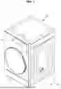


Sources:
- United States Patent and Trademark Office - verify current appl. status at the USPTO↗
Similar patent applications:
- » 20210047773
Apparatus for controlling clothes treating apparatus, clothes treating apparatus and method for controlling clothes treating apparatus - » 20250243616
CLOTHES TREATING APPARATUS AND METHOD FOR CONTROLLING CLOTHES TREATING APPARATUS - » 20240125032
LAUNDRY TREATING APPARATUS AND CONTROL METHOD OF LAUNDRY CLOTHING TREATING APPARATUS - » 20090241367
Cloth treating apparatus and controlling method thereof - » 20100132129
Clothes treating apparatus and controlling method thereof - » 20110005097
CLOTHES TREATING APPARATUS AND CONTROLLING METHOD THEREOF - » 20090241268
Cloth treating apparatus and controlling method thereof - » 20090260254
Clothes treating apparatus and controlling method thereof - » 20110030147
Controlling method of clothes treating apparatus - » 20160115638
Clothes treating apparatus and control method thereof
Recent applications in this class:
- » 20260168165 2026-06-18
METHOD TO DETERMINE AN END OF CYCLE CONDITION OF A LAUNDRY-DRYING CYCLE AND LAUNDRY DRYING MACHINE TO CARRY OUT SAID METHOD - » 20260132566 2026-05-14
ADJUSTABLE DRYER BASED ON WEATHER - » 20260071377 2026-03-12
ELECTRONIC DEVICE AND CONTROL METHOD THEREFOR - » 20260049444 2026-02-19
LAUNDRY DRYER CONTROL SYSTEM - » 20260049443 2026-02-19
DRYER AND METHOD FOR CONTROLLING THE SAME - » 20260028767 2026-01-29
CLOTHES TREATMENT APPARATUS - » 20250382738 2025-12-18
CONTROL METHOD FOR CLOTHES TREATING APPARATUS, CLOTHES TREATING APPARATUS, AND READABLE STORAGE MEDIUM - » 20250347046 2025-11-13
DRYER ACCESSORY AND DRYER - » 20250341045 2025-11-06
DRYER APPLIANCE AND METHOD FOR DRYER CYCLE CONTROL - » 20250341044 2025-11-06
DRYER APPLIANCE AND METHOD FOR DRYER CYCLE CONTROL