SYSTEM AND METHOD FOR PRODUCING FIBER MOLDED PRODUCTS
US20260185302A1
2026-07-02
19/552,412
2026-02-27
Smart Summary: A system has been created to make molded fiber products efficiently. It uses a wet press that can hold multiple molds to shape wet fiber mats. The wet press can move to align different molds in a cycle, allowing the production of two different fiber mats at the same time. After the wet pressing, the mats are transferred to a dry press that can dry both mats simultaneously. This method streamlines the process of making fiber molded items. 🚀 TL;DR
Abstract:
A system for producing molded fiber articles includes a wet press subsystem including a forming platen for carrying a single forming die, and a wet press platen assembly for carrying a plurality of wet press dies, including at least a first wet press die and a second wet press die. The wet press platen assembly is movable relative to the forming platen to alternately align the first and second wet press dies with the forming die in successive cycles of the wet press subsystem to produce one first wet pressed fiber mat and one second wet pressed fiber mat. The system further includes a dry press having at least a first dry press station and a second dry press station, the first dry press station and the second dry press station configured to receive one first wet pressed mat and one second wet pressed mat, respectively, and the dry press closable to simultaneously close the first and second dry press stations to produce dry pressed first and second fiber mats.
Applicant:
Interested in similar patents?
Get notified when new applications in this technology area are published.
Classification:
D21G9/0036 » CPC main
Other accessories for paper-making machines; Paper-making control systems controlling the press or drying section
D21J3/12 » CPC further
Manufacture of articles by pressing wet fibre pulp, or papier-mâché, between moulds of sheets; of diaphragms
D21G9/00 IPC
Other accessories for paper-making machines
Description
The present application is a continuation of International Application No. PCT/CA2024/051146, filed on Sep. 3, 2024, which claims the benefit of priority from co-pending U.S. provisional Ser. No. 63/580,169 , filed on Sep. 1, 2023, the entire contents of which are incorporated herein by reference in the entirety.
FIELD
The teaching disclosed herein relates to systems and method for producing fiber molded products, and in particular, to automated, high-volume production systems.
INTRODUCTION
U.S. Pat. No. 6,716,319 (Gale) discloses an apparatus for producing a molded pulp product from a fiber slurry comprising a dip tank containing a fiber slurry therein and having a liquid level. A platen is provided. A porous mold is carried by the platen. The platen and the mold carried thereby are lowered into the fiber slurry in a downward direction with the platen being disposed upwardly of the mold so that the mold is introduced through the liquid level into the fiber slurry. A vacuum is supplied to the platen and to the mold while the mold is disposed in the fiber slurry to cause fibers in the fiber slurry to collect onto the mold and form a wet molded pulp product. The platen and the mold with the wet molded product thereon are moved out of the fiber slurry through the liquid level to permit water to drain from the mold and the wet molded pulp product. The wet molded pulp product is then dried.
U.S. Pat. No. 11,479,919 (Parker) discloses contoured articles formed in a mold from a fiber slurry. The articles comprise a blend of cellulose fibers and cellulose ester, such as cellulose ester staple fibers. The articles are described as being suitable in a wide array of end uses, including as cups, lids, boxes or pouches, storage containers, trays, plates, food trays, cutlery, coffee cups, coffee cup lid, packaging, bowls, clam shells, bottle caps, straws, covers, and packaging inserts.
U.S. Pat. Appn. Publication No. 2022/0388201 (Knoll) discloses a first molding station for the partial-molding and pre-molding of molded parts made of fibrous material, a fiber molding system with such a first molding station and a method for operating this first molding station or the fiber molding system, and a molded part produced using such a method.
U.S. Pat. Appn. Publication No. 2023/0243107 (Hagenauer) discloses a fiber-forming process in a fiber-forming system having a molding station for molding, a preforming station for preforming, a hot-pressing station for final shaping a formed part made of environmentally-friendly-degradable fiber material. The fiber-forming system produces the formed part having the above stations by means of the method performed in the fiber-forming system as a fiber-forming process.
SUMMARY
The following summary is intended to introduce the reader to various aspects of the applicant's teaching, but not to define any invention.
In one aspect, a system for producing molded fiber articles includes: (a) a wet press subsystem including a forming platen with a forming die mounting surface for carrying a single forming die, and a wet press platen assembly with a plurality of wet press stations for carrying respective wet press dies, wherein the plurality of wet press stations includes at least a first wet press station and a second wet press station for carrying a first wet press die and a second wet press die, respectively, the wet press platen assembly movable relative to the forming platen to alternately align the first and second wet press dies with the forming die in successive cycles of the wet press subsystem to produce one first wet pressed fiber mat and one second wet pressed fiber mat in said successive cycles, respectively, wherein the first and second fiber mats correspond in size and shape to one or more of the molded fiber articles being produced, and (b) a dry press subsystem comprising a dry press having a plurality of dry press stations equal in quantity to the plurality of wet press stations and including at least a first dry press station and a second dry press station, the first dry press station and the second dry press station configured to receive one first wet pressed mat and one second wet pressed mat, respectively, and the dry press closable to simultaneously close the first and second dry press stations to produce dry pressed first and second fiber mats.
In some examples, the system further includes a wet-to-dry transfer subsystem, the wet-to-dry transfer subsystem having a first wet-to-dry carrier member alignable with the first wet press station to receive one of said first fiber mats therefrom, and a second wet-to-dry carrier member alignable with the second wet press station to receive one of said second fiber mats therefrom, and the wet-to-dry transfer subsystem configured to move each of the first and second wet-to-dry carrier members to the first and the second dry press respectively, and load the first and the second fiber mats into the first and second dry press stations, respectively.
According to some aspects, a system for producing molded fiber articles includes (a) a wet press subsystem comprising a single forming platen and a wet press platen assembly defining a plurality of wet press stations, the wet press subsystem configured to produce a plurality of wet pressed fiber mats, each wet press station producing a single wet pressed fiber mat in a corresponding single cycle of the wet press subsystem, and (b) a dry press subsystem comprising a plurality of dry press stations, each dry press station configured to receive a respective one of the wet pressed fiber mats produced by a respective wet press station of the plurality of wet press stations, and to simultaneously close the dry press stations to produce a corresponding plurality of dried fiber mats.
In some examples, the system further includes a wet-to-dry transfer subsystem, the wet-to-dry transfer subsystem comprising a plurality of wet-to-dry carrier members each corresponding to one of the plurality of wet press stations, the wet-to-dry transfer subsystem configured to load a wet pressed fiber mat from a respective wet press station in to a respective wet-to-dry carrier member, and to move each wet-to-dry carrier member to a dry press and load the wet pressed fiber mats into respective ones of the dry press stations.
According to some aspects, a method of operating a fiber molding system for producing molded fiber articles includes opening a dry press to simultaneously open a first dry press station and a second dry press station, loading a first wet fiber mat and a second wet fiber mat in parallel into the first and second dry press stations, respectively and unloading a first and second dried fiber mat in parallel out of the first and second dry press stations, respectively, wherein the dry press loading and unloading are performed at least partially simultaneously.
In some examples, the first and second wet fiber mats are loaded into first mold portions on one side of each dry press station, and the first and second dried fiber mats are unloaded from second mold portions of each dry press station opposite the first mold portions.
In some examples, the method further includes operating a wet press upstream of the dry press to produce the first wet fiber mat and the second wet fiber mat in alternating successive cycles of the wet press.
In some examples, producing the first wet fiber mat comprises engaging a first wet press die with a forming die, and producing the second fiber mat comprises engaging a second wet press die with the forming die.
In some examples, loading the first wet fiber mat and a second wet fiber mat into the first and second dry press stations, respectively, includes moving first and second carriers of a wet-to-dry transfer system into the first and second dry press stations, respectively.
In some examples, unloading the first and second dried fiber mats out of the first and second dry press stations, respectively, includes moving first and second carriers of a dry-to-trim transfer subsystem into the first and second dry press stations, respectively.
According to some aspects, a method of operating a dry press subsystem for producing a fiber pump molded product includes loading a plurality of wet fiber mats in parallel into a respective plurality of dry press stations and unloading a plurality of dried fiber mats in parallel out of the respective plurality of dry press stations, wherein loading and unloading are performed at least partially simultaneously.
In some examples, loading the plurality of wet fiber mats into the plurality of dry press stations, respectively, comprises moving respective upstream carriers of a wet-to-dry transfer system into the plurality of dry press stations, respectively.
In some examples, unloading the plurality of dried fiber mats out of the respective plurality of dry press stations comprises moving respective downstream carriers of a dry-to-trim transfer subsystem into the plurality of dry press stations, respectively.
According to some aspects, a system for producing fiber molded articles, the system includes a wet press subsystem that includes an open vessel for holding a fiber slurry, a wet press support frame, a forming platen having an attached forming die shaped to form the article, wherein the forming platen is rotatably attached to the wet press support frame to rotate between a dipping orientation in which the forming die is positioned to contact the fiber pulp slurry in the vessel, and a pressing orientation in which the forming die is positioned outside of the fiber pulp slurry in the vessel, a wet press platen assembly defining a plurality of wet press stations for holding a plurality of wet press dies, each wet press die shaped to cooperate with the forming die to form a fiber mat corresponding in size and shape one or more of the articles being produced, the wet press platen assembly rotatable relative to the wet press support frame to rotate each of the plurality of wet press dies, individually, into a pressing orientation in which the wet press die is disposed opposite to the forming die in the pressing orientation, wherein at least one of the forming platen or the plurality of wet press stations is movably attached to the wet press support frame to move between a wet press open configuration in which the forming platen and the plurality of wet press stations are spaced apart from each other, and a wet press closed configuration in which the forming platen in the pressing orientation and one of the wet press stations in the pressing orientation are positioned to compress the fiber mat between them.
In some examples, the wet press subsystem further includes a forming platen actuator coupled to the forming platen to drive rotation of the forming platen assembly between the dipping orientation and the pressing orientation, a wet press platen actuator coupled to the wet press platen assembly to selectively orient one of the wet press platen stations in the pressing orientation, and a compression actuator coupled to at least one of the forming platen and the wet press platen assembly to drive movement of at least one of the forming platen and the wet press platen assembly between the wet press open configuration and the wet press closed configuration, and a wet press controller comprising a processor operatively connected to the forming actuator, the wet press platen actuator, the compression actuator and a memory comprising a non-transitory computer-readable medium storing instructions executable by the processor to control the forming actuator to rotate the forming platen between the dipping orientation and the pressing orientation, control the wet press platen actuator to rotate each one of the plurality of wet press platen stations into the pressing orientation, and control the compression actuator to move at least one of the forming platen and the plurality of wet press platen stations between the wet press open configuration to the wet press closed configuration.
In some examples, the system further includes a trim press subsystem including a trim press having a pair of trim press platens adapted to trim the fiber mat, wherein the trim press is actuatable between (i) a trim press open configuration, in which the trim press platens are spaced apart from each other to permit ingress of the fiber mat between the trim press platens, and (ii) a trim press closed configuration, in which the trim press platens are positioned to compress the fiber mat between them, and a dry-to-trim transfer subsystem including a dry-to-trim transfer support frame and a plurality of dry-to-trim carrier members equal in number to the number of dry presses, with each one of the dry-to-trim carrier members associated with a different one of the dry press stations, wherein each of the dry-to-trim carrier members is shaped to hold the product and is movably attached to the dry-to-trim transfer support frame to move between a pick-up position to receive the product from the associated one of the dry press stations, and a drop-off position to place the product on the trim press.
Other aspects and features of the teachings disclosed herein will become apparent to those ordinarily skilled in the art, upon review of the following description of the specific examples of the present disclosure.
DRAWINGS
For a better understanding of the described examples and to show more clearly how they may be carried into effect, reference will now be made, by way of example, to the accompanying drawings in which:
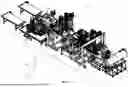
FIG. 1 is a left-rear perspective view of an embodiment of a system of the present disclosure for producing a fiber pulp molded product.
FIG. 2A is a left-rear perspective view of a first portion of the system of FIG. 1 at an enlarged scale relative to FIG. 1.
FIG. 2B is a left-rear perspective view of a second portion of the system of FIG. 1 at an enlarged scale relative to FIG. 1.
FIG. 3 is a top plan view of the system of FIG. 1.
FIG. 4 is a left side elevation view of the system of FIG. 1.
FIG. 5A is a left side elevation view of a first portion of the system of FIG. 1, at an enlarged scale relative to FIG. 4
FIG. 5B is a left side elevation view of a second portion of the system of FIG. 1, at an enlarged scale relative to Figure.
FIG. 6 is a functional block diagram of actuators and a controller of the system of FIG. 1.
FIGS. 7A to 7H are right-rear perspective views of the wet press subsystem of the system of FIG. 1, showing stages of motion of the wet press subsystem. FIG. 7A shows the forming platen in a dipping orientation and dipping position, and the first wet press platen in the pressing orientation. FIG. 7B shows the forming platen raised to an intermediate position. FIG. 7C shows the forming platen rotating from the dipping orientation toward the pressing orientation. FIG. 7D shows the forming platen in the pressing orientation. FIG. 7E shows the forming platen in the pressing orientation and the first wet press platen in the pressing orientation, and the forming platen and the first wet press platen in the wet press closed configuration. FIG. 7F shows the forming platen lowered to an intermediate position. FIG. 7G shows the forming platen in a dipping orientation and dipping position, and the second wet press platen in the pressing orientation. FIG. 7H shows the first and second wet press platens in their transfer orientations.
FIG. 8 is a right-rear perspective view of the wet press subsystem and wet-to-dry transfer subsystem of the system of FIG. 1.
FIG. 9 is a right-rear perspective view of the wet-to-dry transfer subsystem and dry press subsystem of the system of FIG. 1.
FIG. 10 is a left-rear perspective view of the wet-to-dry transfer subsystem and the dry press subsystem of the system of FIG. 1.
FIG. 11 is a left-rear perspective view of the dry press subsystem of the system of FIG. 1.
FIG. 12 is a left-front perspective view of the dry press subsystem of the system of FIG. 1.
FIG. 13 is a right-front perspective view of the dry press subsystem of the system of FIG. 1.
FIG. 14 is a right-rear perspective view of the dry press subsystem and the dry-to-trim transfer subsystem of the system of FIG. 1.
FIG. 15 is a right-rear perspective view of the dry press subsystem and the dry-to-trim transfer subsystem of the system of FIG. 1.
FIG. 16 is a left-rear perspective view of the dry press subsystem and the dry-to-trim transfer subsystem of the system of FIG. 1.
FIG. 17 is a left-rear perspective view of the dry-to-trim transfer subsystem of the system of FIG. 1.
FIG. 18 is a left-rear perspective view of the dry-to-trim transfer subsystem, the trim subsystem, and the conveyor belt subsystem of the system of FIG. 1.
FIG. 19 is a right-rear perspective view of the trim subsystem and the conveyor belt subsystem of the system of FIG. 1.
FIG. 20 is a bottom right-rear perspective view of the trim subsystem and the conveyor belt subsystem of the system of FIG. 1.
FIG. 21 is left-rear perspective view of the trim subsystem, the trim-to-conveyor transfer subsystem, and the conveyor belt subsystem of the system of FIG. 1.
FIG. 22 is right-rear perspective view of the trim subsystem, the trim-to-conveyor transfer subsystem, and the conveyor belt subsystem of the system of FIG. 1.
FIGS. 23A and 23B are side views of a prior art double press that may be used for the dry press subsystem of the system of FIG. 1. FIG. 23A shows the double press in the open configuration. FIG. 23B shows the double press in the closed configuration.
FIG. 24 is a plan view of the dry press subsystem, the wet-to-dry transfer subsystem, and the dry-to-trim transfer subsystem of FIG. 1, with the dry press subsystem in the open configuration.
The drawings included herewith are for illustrating various examples of apparatuses and methods of the teaching of the present specification and are not intended to limit the scope of what is taught in any way.
DETAILED DESCRIPTION
Various apparatuses or processes will be described below to provide an example of each claimed invention. No example described below limits any claimed invention and any claimed invention may cover processes or apparatuses that differ from those described below. The claimed inventions are not limited to apparatuses or processes having all of the features of any one apparatus or process described below or to features common to multiple or all of the apparatuses described below. It is possible that an apparatus or process described below is not an example of any claimed invention. Any invention disclosed in an apparatus or process described below that is not claimed in this document may be the subject matter of another protective instrument, for example, a continuing patent application, and the applicants, inventors, or owners do not intend to abandon, disclaim, or dedicate to the public any such invention by its disclosure in this document.
“Fiber pulp slurry”, as used herein, refers to a liquid in which fibers are suspended. In a non-limiting example, the liquid comprises water and the fibers comprise cellulosic material including (without limitation) fibers derived from paper materials such as (without limitation) recycled newsprint and/or cardboard.
“Platen”, as used herein, refers to a part of a press to which pressure may be applied so that the material between a pair of platens is subjected to the applied pressure. In a non-limiting example, a platen may have a substantially planar (i.e., plate) form and be made of steel. In other embodiments, a platen may have other shapes and be made of other materials.
“Mold part”, as used herein, refers to a portion of a mold having a shape conforming a side of a product to be produced. Mold parts that are complementary in shape with each other may be associated in a pair. For example, within such a pair, one mold part may be referred to as an A-side or cavity side, while the other mold part may be referred to as a B-side or a core side.
“Actuator”, as used herein, refers to a device that converts energy, such as electric voltage, pneumatic pressure, or hydraulic fluid pressure, into motion of a moving part. In some embodiments, an actuator may be a rotary actuator that includes an electrically powered stepper motor or servomotor. In some embodiments, an actuator may be a linear actuator that includes a hydraulically or pneumatically powered cylinder.
“Processor”, as used herein, refers to one or more electronic devices that is/are capable of reading and executing instructions stored on a memory to perform operations on data, which may be stored on a memory or provided in a data signal. Non-limiting examples of processors include devices referred to as microprocessors, microcontrollers, microcontroller units (MCU), central processing units (CPU), digital signal processors, field programmable gate arrays (FPGAs), and programmable logic controllers (PLCs).
“Memory”, as used herein, refers to a non-transitory tangible computer-readable medium for storing information in a format readable by a processor, and/or instructions readable by a processor to implement an algorithm. Non-limiting types of memory include solid-state, optical, and magnetic computer readable media. Memory may be non-volatile or volatile. Instructions stored by a memory may be based on a plurality of programming languages known in the art, with non-limiting examples including the C, C++, Python TM, MATLAB TM, and Java TM programming languages.
Overview of Systems
FIGS. 1 to 5B show an embodiment of a system 2 of the present disclosure for producing and processing molded fiber articles. As a non-limiting example, the molded fiber articles may be containers used for packaging of food items. The system 2 includes the following subsystems arranged from an upstream end of the process to a downstream end of the process, in the following order: a wet press subsystem 4; a wet-to-dry transfer subsystem 6, a dry press subsystem 8; a dry-to-trim transfer subsystem 10; a trim press subsystem 12; a trim-to-conveyor transfer subsystem 14, and a conveyor belt subsystem 16. The system 2 also includes, as shown in the functional block diagram of FIG. 6, a controller 18 operatively connected to actuators of the foregoing subsystems. The subsystems are described in greater detail below.
In the example illustrated, the process flow extends along a horizontal longitudinal axis (L) (see, e.g., FIG. 1). In this specification, three mutually orthogonal axes are referenced, namely, the horizontal longitudinal axis (L), a horizontal transverse axis (T), and a vertical axis (V). For more convenient description, the terms longitudinal and transverse are used herein to refer to directions that are parallel to the longitudinal axis and the transverse axis, respectively. The positive signs (+) and arrowheads on these axes indicate positive directions along these axes, whereas negative directions are opposite thereto. The positive and negative longitudinal directions may be referred to as forward and rearward directions, respectively. The positive and negative transverse directions may be referred to as leftward and rightward directions, respectively.
Wet Press Subsystem
FIGS. 7A to 7H show an embodiment of a wet press subsystem 4 in different stages of operation. A purpose of the wet press subsystem 4 is to produce a wet pressed article having a desired shape from a fiber pulp slurry. The wet press subsystem 4 includes an open vessel or slurry tank 20, a wet press support frame 22, a forming platen 24, a forming mold part (forming die) 26, and a forming platen actuator 28. The wet press subsystem 4 further includes, in the example illustrated, a wet press platen assembly 30 having a plurality of wet press die mounting surfaces defining a respective plurality of wet press stations 30a, 30b. A plurality of wet press dies (or mold parts) 32a, 32b are provided, each associated with a respective wet press station. The wet press subsystem 4 further includes a shaft 34, a wet press platen actuator 36, and a compression actuator (pressing actuator) 38. The wet press subsystem 4 also includes a controller 18 shown in the functional block diagram of FIG. 6.
The vessel 20 is used to contain a fiber pulp slurry. The vessel 20 is open to allow the forming platen 24 to be dipped into the fiber pulp slurry in the vessel 20.
The wet press support frame 22 is used to support the forming platen 24 and the wet press platens 30 on a floor surface or other structure, so that the forming platen 24 and the wet press platens 30 can be rotated relative to the wet press support frame 22.
The forming platen 24 has an attached forming die 26 (FIG. 7D) that is shaped to form a fiber mat that corresponds to a set of the molded fiber articles produced per cycle of the wet press subsystem. In the example illustrated, the fiber mat corresponds to a set of sixteen molded fiber articles. The forming mold part 26 generally defines, in the example illustrated, a core side of a mold.
The forming platen 24 is rotatably attached to the wet press support frame 22 such as by means of a shaft 40 that is supported in a journal bearing attached to the wet press support frame 22 so as to be rotatable about a transverse axis.
The forming platen actuator 28 is coupled (directly, or indirectly via a shaft) to the forming platen 24 to drive rotation of the forming platen 24 relative to the wet press support frame 22. In the embodiment shown in the Figures, the forming platen actuator 28 is in the form of a rotary actuator that includes an electrically powered stepper motor or servomotor. In other embodiments, the rotary actuator may be pneumatically or hydraulically powered. In still other embodiments, the forming platen actuator 28 may be a linear actuator that includes a hydraulic cylinder that is coupled to the forming platen 24 by a cam mechanism to convert linear motion of the hydraulic cylinder into rotational motion of the forming platen 24.
The forming platen actuator 28 drives rotation of the forming platen 24 between a dipping orientation and a pressing orientation. FIG. 7A shows the forming platen 24 in the dipping orientation (facing downwards) and dipping position in which the forming mold part 26 is positioned to contact the fiber pulp slurry in the vessel 20. FIG. 7B shows the forming platen 24 having moved upwardly. FIG. 7C shows the forming platen 24 rotating about the traverse axis to an intermediate orientation toward the pressing orientation. FIG. 7D shows the forming platen 24 rotated into the pressing orientation (facing upwards) in which the forming mold part 26 is disposed opposite to one of the wet press mold parts 32, as will be described below. Accordingly, in the embodiment shown in the Figures, the dipping orientation and the pressing orientation are separated by an angular displacement of 180 degrees.
In the example illustrated, the plurality of wet press stations consists of two wet press stations, namely, a first wet press station 30a and a second wet press station 30b. Other embodiments may have any integer number of wet press stations greater than two. Each of the wet press stations has an attached wet press mold part or die (i.e. a first wet press die 32a, second wet press die 32b) that is shaped to cooperate with the forming die to produce the desired wet pressed article. In the embodiment shown in FIG. 7A, each wet press die 32a, 32b corresponds to a cavity side of a mold. The wet press stations 30a, 30b are spaced apart from each other on the wet press assembly 30 and are separately alignable with the forming die. In the example illustrated, the first and second wet press stations 30a, 30b are spaced apart on opposite sides of the wet press platen axis. Accordingly, when one of wet press stations is oriented upwards, the other one of the wet press stations is oriented downwards. The shaft 34 is rotatably attached to the wet press support frame 22 such as by means of a journal bearing attached to the wet press support frame 22 that allows the shaft 34 and the attached wet press platen assembly 30 to rotate about the transverse wet press platen axis.
The wet press platen actuator 36 is coupled via the shaft 34 to drive rotation of the wet press platen assembly 30 relative to the wet press support frame 22. In the embodiment shown in the Figures, the wet press platen actuator 36 is in the form of a rotary actuator that includes an electrically powered stepper motor or servomotor. In other embodiments, the wet press platen actuator 36 may have different forms analogous to those described above in respect to the forming actuator.
The wet press platen actuator 36 drives rotation of the wet press platen assembly 30, to selectively (and sequentially) move each one of the wet press stations (i.e., one at a time), into a pressing orientation in which the wet press station is disposed opposite to the forming platen 24 when the forming platen is in the pressing position. For example, FIG. 7D shows the first wet press station 30a facing downward in the pressing orientation, while the second wet press station 30b is facing upwards. By rotating the wet press platen assembly 180 degrees (FIG. 7G), the first wet press station 30a is oriented to face upward, and the second wet press station 30b is oriented to face downwards.
The wet press platen assembly 30 is also rotatable into a transfer orientation in which the wet press stations 30a, 30b are oriented to facilitate engagement by a part handling apparatus (e.g. by a transfer subsystem). For example, as shown in FIG. 7H, when rotated to a transfer orientation, the first and second wet press stations 30a, 30b are oriented vertically, and directed transversely outwardly.
At least one of the forming platen 24 and the wet press platen assembly 30 is/are movably attached to the wet press support frame 22 to move between a wet press open configuration and a wet press closed configuration. The compression actuator 38 is coupled directly or indirectly to the forming platen 24 and/or the plurality of wet press platens 30 to drive movement of the forming platen 24 and/or the plurality of wet press platens 30 between the wet press open configuration and the wet press closed configuration. In the embodiment shown in the Figures, the compression actuator 38 is implemented by a rotary actuator that drives rotation of a chain lift mechanism attached to the forming platen 24 to raise or lower the forming platen 24. In the wet press open configuration, the forming platen 24 and the wet press platen assembly 30 are spaced apart from each other. For example, FIG. 7D shows the forming platen 24 and the wet press platen assembly 30 in the wet press open configuration. In the wet press closed configuration, the forming platen 24 is in the pressing orientation (facing upward) and a selected one of the wet press stations 30a, 30b is in a complimentary pressing position (facing downward), for compressing a fiber mat between them to form the wet pressed article. For example, FIG. 7E shows the forming platen 24 in the pressing orientation and the first wet press station 30a in a complimentary pressing orientation, so that the forming die is engaged with the first wet press die. The compression actuator 38 urges the forming platen upward, to press the forming die against the wet press die and form the wet pressed article. In other embodiments, it is possible that the compression actuator 38 only drives movement of the wet press platens 30, or drives movement of both the forming platen and the wet press platen assembly 30.
Referring to FIG. 6, the controller 18 (which may be referred to as a wet press controller in the context of controlling the wet press subsystem 4) includes a processor 42 that is operatively connected to the forming platen actuator 28, the wet press platen actuator 36, the compression actuator 38, and a memory 44. The memory 44 stores instructions executable by the processor 42 to control the forming platen actuator 28, the wet press platen actuator 36, and the compression actuator 38 so that these actuators control movement of the forming platen 24 and the wet press platens 30 in a coordinated manner to form the product, as follows. Referring to FIG. 7A, the forming platen 24 is in the dipping orientation and dipping position so that the forming platen 24 contact the fiber pulp slurry in the reservoir. Vacuum is applied, and as a result, a layer of the fiber pulp (fiber mat) is deposited on the forming die 26.
Referring to FIG. 7B, the compression actuator 38 then lifts the forming platen 24 to an intermediate position. Referring to FIGS. 7C to 7D, the forming platen actuator 28 rotates the forming platen 24 by 180 degrees about a transverse axis into the pressing orientation. Referring to FIG. 7E, the compression actuator 38 continues lifting the forming platen 24 into engagement with the first wet press station 30a (and die 32a) so that the fiber mat on the forming die 24 is compressed therebetween to form a first wet pressed fiber mat. Releasable retention of the first fiber mat on the first wet press die 32a may be vacuum-assisted.
Referring to FIG. 7G, the combined action of the forming platen actuator 28 and the compression actuator 38 returns the forming platen 24 to the dipping orientation and the dipping position so that the forming die 26 is recoated with a second fiber mat. Meanwhile, the wet press platen actuator 36 rotates the wet press platen assembly 30 by 180 degrees about the transverse axis so that the second wet press station 30b is in the pressing orientation. In a manner analogous to that previously described with reference to FIGS. 7B to 7E, the forming platen actuator 28 returns the forming platen 24 to the pressing orientation, and the compression actuator 38 lifts the forming platen 24 into engagement with the second wet press platen 30b in the pressing orientation so that the second fiber mat on the forming die 26 is compressed therebetween to form a second wet pressed fiber mat. Releasable retention of the second fiber mat on the second wet press die 32b may be vacuum-assisted.
As a result of this sequence of operations, the first wet press station 30a is loaded with a first fiber mat, while the second wet press station 30b is loaded with a second fiber mat. Referring to FIG. 7H, the compression actuator 38 lowers the forming platen 24 to an intermediate position, and the wet press platen actuator 36 rotates the wet press platens 30 into the transfer orientations for pick up by the wet-to-dry transfer subsystem 6 as described below. The foregoing sequence of motions may then be repeated to form additional instances of the first and second fiber mats.
Dry Press Subsystem
FIGS. 11 to 13 show different views of the dry press subsystem 8 in isolation.
A purpose of the dry press subsystem 8 is to compress and reduce the moisture content of the fiber mats formed by the wet press subsystem 4. It will be understood that the terms “wet” in “wet press” and “dry” in “dry press” are used to differentiate these presses from each other, and are not limited by any moisture content of the produced product.
The dry press subsystem 8 includes a plurality of dry press stations 46a, 46b (generally denoted 46). In the example illustrated, the dry press stations are part of a single dry press machine, and each station moves between mold-open and mold-closed positions synchronously with the dry press machine. The number of dry press stations is, in the example illustrated, equal to the number of wet press stations. In some embodiments the number of dry press stations may be greater than the number of wet press stations. In the embodiment illustrated, the wet press subsystem 4 has two wet press stations 30a, 30b, and the dry press subsystem 8 includes two dry press stations 46a, 46b. In the example illustrated, the first dry press station 46a is associated with the first wet press station 30a in the sense that the first dry press station 46a is used to process the first fiber mat formed using the first wet press station 30a. The second dry press station 46b is associated with the second wet press station 30b in the sense that the second dry press station 46b is used to process the second fiber mat formed using the second wet press station 30b.
Each of the dry press stations 46a, 46b is disposed between opposed platen faces of the dry press machine. In the example illustrated, the dry press machine is configured as a horizontal stack mold machine, with a base supporting a stationary platen, a movable platen, and a center platen disposed between the stationary and moving platens. The first dry press station 46a is disposed between opposed faces 48a, 48a of the stationary platen and the center platen. The second dry press is disposed between opposed faces 48b, 48b of the moving platen and the center platen.
Each dry press platen face 48a, 48b has a dry press mold part 50 mounted thereto, that is complementary to a shape of the fiber mat formed by the wet press subsystem 4. In embodiments, one or all of the dry press platens may be attached to or integrated with a heat source such as an electric heating element, or define conduits for through flow of a heated fluid (e.g. heated oil or steam) to heat the dry press mold parts 50. In this embodiment shown in the Figures, the dry press platens have vertically oriented faces to which the molds can be attached. In the example illustrated, the inner dry press mold parts 50 (i.e., those that are mounted to the center platen) are cavity side mold parts, whereas the outer dry press mold parts 50 (i.e., those that are mounted to the stationary and moving platens) are core side mold parts.
Each of the dry press stations 46a, 46b is actuatable between a dry press open configuration in which the dry press platens 48 are spaced apart from each other to permit ingress of the product between the dry press platens 48, and a dry press closed configuration in which the dry press platens 48 are positioned to compress the product between them. FIGS. 9 to 13 show the dry press platens 48 in the dry press open configuration. The dry press is closable to simultaneously close the first and second dry press stations to produce dry pressed first and second fiber mats in a single cycle of the dry press.
To assist understanding operation of the dry press machine configured as a two-station stack mold, reference is also made to the press 52 shown in FIGS. 23A and 23B, which is further described in U.S. patent application publication no. US2016/0303785 A1 (Segal; 2016-10-20), the entire contents of which are incorporated herein by reference, where permitted. The press 52 has two press stations 53a and 53b. For the first press station 53a, a mold part 54 is mounted on a stationary platen 56 and a mold part 58 mounted on an immediately adjacent side of a center platen 60. For the second press, a mold part 61 mounted on a moving platen 62 and a mold part 64 is mounted on the immediately adjacent side of the center section 60. The mold sections are mounted on and translate over tie bars 66. A linkage mechanism 68 includes a central link member 70 pivotally connected to the center section 60, a first link arm 72 which is pivotally connected at one end to the central link member 70 and pivotally connected at the other end to the stationary platen 56, and a second link arm 74 which is pivotally connected at one end to the central link member 70 and pivotally connected at the other end to the moving platen 62. A drive means (not shown) such as a hydraulic cylinder or a rotary actuator may be used to drive movement of the presses from the open configuration (FIG. 23A) to the closed configuration (FIG. 23B). It will be understood that the dry presses 46 shown in FIGS. 9 to 13 may operate in an analogous manner.
Wet-to-Dry Transfer System
FIG. 8 shows the wet press subsystem 4 in conjunction with an embodiment of a wet-to-dry transfer subsystem 6, and FIGS. 9 and 10 show different views of the wet-to-dry transfer subsystem 6 in conjunction with the dry press subsystem 8.
A purpose of the wet-to-dry transfer subsystem 6 is to move the products formed by the wet press subsystem 4 to the dry press subsystem 8. The wet-to-dry transfer subsystem 6 includes a wet-to-dry transfer support frame 76 and a plurality of wet-to-dry carrier members 78a, 78b (generally denoted 78). The number of wet-to-dry carrier members 78 is at least equal in number to the number of wet press platens 30. In the embodiment shown the figures, the wet press subsystem 4 has two wet press platens 30, and accordingly the wet-to-dry transfer subsystem 6 includes two wet-to-dry carrier members 78. The first wet-to-dry carrier member 78a is associated with the first wet press platen 30a and the first dry press 46a in the sense that the first wet-to-dry carrier member 78a is used to move the first product produced using the first wet press platen 30a to the first dry press 46a; the second wet-to-dry carrier member 78b is associated with the second wet press platen 30b and the second dry press 46b in the sense that the second wet-to-dry carrier member 78b is used to move the second product produced using the second wet press platen 30b to the second dry press 46b.
Each of the wet-to-dry carrier members 78 is shaped to hold the product and is movably attached to the wet-to-dry transfer support frame 76 to move between a pick-up position and a drop-off position. In the pick-up position, the wet-to-dry carrier member 78 is positioned to receive the product from the associated one of the wet press platens 30 in the transfer orientation. In the drop-off position, the wet-to-dry carrier member is positioned to place the product on the associated one of the dry presses 46. Releasable retention of the product on the wet-to-dry carrier members 78 may be vacuum-assisted.
At least one wet-to-dry actuator 80 (FIG. 6) is coupled to each one of the wet-to-dry carrier members 78 to drive movement of the wet-to-dry carrier member 78 relative to the wet-to-dry transfer support frame 76 between the pick-up position and the drop-off position. In the embodiment shown in the Figures, each wet-to-dry carrier member 78 is in the form of a core side mold part. A motor is coupled to the wet-to-dry carrier member 78 to drive its translational movement along an elongate boom 82a or 82b (generally denoted 82) that extends in the longitudinal direction. The boom 82 is movably attached to a gantry 84 that extends upwardly from the wet-to-dry transfer support frame 76. Chain drive mechanisms drive movement of the boom 82 vertically, longitudinally, and transversely in relation to the gantry 84. The motor and the chain drive mechanisms may be considered to be embodiments of the at least one wet-to-dry actuator 78. For example, FIG. 8 shows the first wet-to-dry carrier member 78a in the pick-up position to receive the first product from the first wet press platen 30a in the transfer orientation. This is achieved by moving the first boom 82a into the rearmost position relative to the gantry 84, and moving the first wet-to-dry carrier member 78a into the rearmost position along the first boom 82a. For example, FIG. 9 shows the second wet-to-dry carrier member 78b in the drop-off position to place the second product in the second dry press 46b, by placing it onto the inner dry press platen 48b of the second dry press 46b. This is achieved by moving the second boom 82b into the forwardmost position relative to the gantry 84, and moving the second wet-to-dry carrier member 78b into the forwardmost position along the second boom 82b.
The wet-to-dry transfer subsystem 6 also includes the controller 18 (which may be referred to as a wet-to-dry controller in the context of controlling the wet-to-dry transfer subsystem 6) shown in the functional block diagram of FIG. 6. The memory 44 stores instructions executable by the processor 42 to control the wet-to-dry actuator 80 to move each of the wet-to-dry carrier members 82 between the pick-up position when the associated one of the wet press platens 30 is in the transfer position and loaded with the product, and the drop-off position when the associated one of the dry presses 46 is in the dry press open configuration to place the product in the associated dry press 46. In embodiments, the first and second wet-to-dry carrier members 78 may move either simultaneously from their respective pick-up positions to their respective drop-off positions so that the first and second products are simultaneously loaded into the first and second dry presses 46, respectively. Therefore, a single wet press subsystem 4 may simultaneously service a plurality of dry presses 46, to increase the productivity of the time used for dry pressing of the products.
Trim Press Subsystem FIGS. 18 to 22 show different views of the trim press subsystem 12.
A purpose of the trim press subsystem 12 is to cut excess portions (e.g., mold flashing on the periphery of the product) off of the product formed by the wet press subsystem 4 and dried by the dry press subsystem 8.
The trim press subsystem 12 includes a trim press 86 comprising a pair of trim press platens 88a, 88b (generally denoted 88) adapted to trim the product. For example, FIGS. 18 to 22 show the trim press 86 having a lower trim press platen 88a and an upper trim press platen 88b. The trim press 86 is actuatable between a trim press open configuration and a trim press closed configuration. In the trim press open configuration, the trim press platens 88 are spaced apart from each other to permit ingress of the product between the trim press platens 88, as shown in FIG. 18 to 22. In the trim press closed configuration, the trim press platens 88 are positioned to compress the product between them, and thereby cut excess portions off of the product. In the embodiment shown, the trim press closed configuration is achieved by lowering the upper trim press platen relative to the lower trim press platen. (While the trim press closed configuration is not shown in the Figures, the operation of the trim press 86 in this regard is conventional.)
Dry-to-Trim Transfer System
FIGS. 14 to 16 show views of the dry press subsystem 8 in conjunction with the dry-to-trim transfer subsystem 10. FIG. 17 shows the dry-to-trim press subsystem 12 in isolation. FIG. 18 shows a view of the dry-to-trim press subsystem 12 in conjunction with the trim press subsystem 12.
A purpose of the dry-to-trim transfer subsystem 10 is to move the products processed by the dry press subsystem 8 to the trim press subsystem 12. The dry-to-trim transfer subsystem 10 includes a dry-to-trim transfer support frame 90 and a plurality of dry-to-trim carrier members 92a, 92b (generally denoted 92). The number of dry-to-trim carrier members 92 is at least equal in number to the number of dry presses 46. In the embodiment shown the figures, the dry press subsystem 8 has two dry presses 46, and accordingly the dry-to-trim transfer subsystem 10 includes two dry-to-trim carrier members 92a, 92b. The first dry-to-trim carrier member 92a is associated with the first dry press 46a in the sense that the first dry-to-trim carrier member 92a is used to move the first product processed by the first dry press 46a to the trim press 86; the second dry-to-trim carrier member 92b is associated with the second dry press 46b in the sense that the second dry-to-trim carrier member 92b is used to move the second product processed by the second dry press 46b to the trim press 86.
Each of the dry-to-trim carrier members 92 is shaped to hold the product and movably attached to the dry-to-trim transfer support frame 90 to move between a pick-up position and a drop-off position. In the pick-up position, the dry-to-trim carrier member is positioned to receive the product from the associated one of dry presses 46. In the drop-off position, the dry-to-trim carrier member 92 is positioned to place the product on the trim press 86. Releasable retention of the product on the dry-to-trim carrier members 92 may be vacuum-assisted.
At least one dry-to-trim actuator 94 (FIG. 6) is coupled to each one of the dry-to-trim carrier members 92 to drive movement of the dry-to-trim carrier member 92 relative to the dry-to-trim support frame between the pick-up position and the drop-off position. In the embodiment shown in the Figures, each dry-to-trim carrier member 92 is in the form of a cavity side mold part. A motor is coupled to the dry-to-trim carrier member 92 to drive its translational movement along an elongate boom 96a or 96b (generally denoted 96) that extends in the longitudinal direction. The boom 96 is movably attached to a gantry 98 that extends upwardly from the dry-to-trim transfer support frame 90. Chain drive mechanisms drive movement of the boom 96 vertically, longitudinally, and transversely in relation to the gantry 98. In addition, a motor drives rotation of the boom 96 along its elongate axis so that the dry-to-trim carrier member and the product retained by it can be rotated from a vertical orientation to pick up the product from the dry press 46, to a horizontal orientation to place the product into the trim press. The motors and the chain drive mechanisms may be considered to be embodiments of the at least one dry-to-trim actuator 94. Referring to FIG. 14, positioning the dry-to-trim carrier member 92 in the pick-up position to receive the product from the dry press is achieved by moving the boom 96 into the rearmost position relative to the gantry 98, and moving the dry-to-trim carrier member 92 into the rearmost position along the boom 96 so that it can pick up the product from the outer dry press platen 48 of the dry press 46. Conversely, the drop-off position is achieved by moving the boom 96 into the forwardmost position relative to the gantry 98, and moving the dry-to-trim carrier member into the forwardmost position along the boom 96, and rotating the boom 96 about its elongate axis to move the dry-to-trim carrier member 92 from a vertical orientation to a horizontal orientation, and moving the boom 96 transversely inward to the trim press 86.
In FIGS. 14-18, the booms 96a and 96b and the dry-to-trim carrier members 92a and 92b and associated elements are shown in orientations that are not necessarily the same as they are during operation. It will be understood by one skilled in the art, and based on the description provided herewith what suitable orientations these components would have during operation.
The dry-to-trim transfer subsystem 10 also includes the controller 18 (which may be referred to a dry-to-trim controller in the context of controlling the dry-to-trim transfer subsystem 10) shown in the functional block diagram of FIG. 6. The memory 44 stores instructions compression executable by the processor 42 to control the dry-to-trim actuator 94 to move each of the dry-to-trim carrier members 92 between the pick-up position when the associated one of the dry presses 46 is in the dry press open configuration, and the drop-off position when the trim press 86 is in the trim press open configuration. In embodiments, the first and second dry-to-trim carrier members 92 may move in sequence from their respective pick-up positions to their respective drop-off positions so that the first and second products are loaded one at a time into the trim press 86. In other embodiments, where the size of the trim press is sufficient to accommodate two products at the same time, first and second dry-to-trim carrier members 92 may move simultaneously from their respective pick-up positions to their respective drop-off positions so that the first and second products are loaded simultaneously into the trim press 86. In either case, a single trim press 86 is used to service a plurality of dry presses 46.
Conveyor Belt Subsystem
FIGS. 18 to 22 show different views of the conveyor belt subsystem 16 in conjunction with the trim subsystem.
A purpose of the conveyor belt subsystem 16 is to transport to the products processed by the trim press away from the trim press. The conveyor belt subsystem 16 includes a pair of motorized conveyor belts 100a and 100b (generally denoted 100). A first conveyor belt 100a is used to transport the first product processed by the trim press, and a second conveyor belt 100b is used to transport the second product away from the trim press. Each of the first and second conveyor belt 100b has a conveyor belt first portion transversely adjacent to the trim press, and a conveyor belt second portion that extends longitudinally forward from the conveyor first portion. A stacking subsystem (not shown) is used to transfer and stack products from the conveyor belt first portions to and on the conveyor belt second portions.
Trim-to-Conveyor Transfer Subsystem
FIGS. 21 and 22 show views of the trim-to-conveyor transfer subsystem 14 in conjunction with the trim press subsystem 12 and the dry-to-trim transfer subsystem 10.
A purpose of the trim-to-conveyor transfer subsystem 14 is to move the products processed by the trim press subsystem 12 to the conveyor belts 100. The trim-to-conveyor transfer subsystem 14 includes a trim-to-conveyor transfer support frame 102 and a plurality of trim-to-conveyor carrier members 104a and 104b (generally denoted 104). The number of trim-to-conveyor carrier members 104 is at least equal in number to the number of dry presses 46. In the embodiment shown the figures, the dry press subsystem 8 has two dry presses 46, and accordingly the trim-to-conveyor transfer subsystem 14 includes two trim-to-conveyor carrier members 104. The first trim-to-conveyor carrier member 104a is used to move the first product processed by the trim press to the first conveyor belt 100a, and associated with the first conveyor belt 100a in this sense; the second trim-to-conveyor carrier member 104b is used to move the second product produced by the trim press to the second conveyor belt 100b, and associated with the second conveyor belt 100b in this sense.
Each of the trim-to-conveyor carrier members 104 is shaped to hold the product and movably attached to the trim-to-conveyor transfer support frame 102 to move between a pick-up position and a drop-off position. In the pick-up position, the trim-to-conveyor carrier member 104 is positioned to receive the product from the trim press. In the drop-off position, the trim-to-conveyor carrier member 104 is positioned to place the product on the associated one of the conveyor belts 100. Releasable retention of the product on the trim-to-conveyor carrier members 104 may be vacuum-assisted.
At least one trim-to-conveyor actuator 106 (FIG. 6) is coupled to each one of the trim-to-conveyor carrier members 104 to drive movement of the trim-to-conveyor carrier member relative to the trim-to-conveyor support frame between the pick-up position and the drop-off position. In the embodiment shown in the Figures, each trim-to-conveyor carrier member 104 is in the form of a core side mold part. The trim-to-conveyor carrier member 104 is attached to an L-shaped arm 108a and 108b (generally denoted 108). A motor drives rotation of the trim-to-conveyor carrier member 104 along a longitudinal axis relative to the arm 108. The arm 108 is attached to a gantry 110 that extends upwardly from the trim-to-conveyor support frame. Chain drive mechanisms drive movement of the arm 108 vertically and transversely in relation to the gantry 110. The motor and the chain drive mechanisms may be considered to be embodiments of the at least one trim-to-conveyor actuator 106. FIG. 21 shows the first trim-to-conveyor carrier member 104a in the drop-off position to place a first product on the first conveyor belt 100a. FIG. 22 shows the second trim-to-conveyor carrier member 104b in the pick-up position to pick-up a second product from the trim press 86.
The trim-to-conveyor transfer subsystem 14 also includes a controller 18 (which may be referred to as a trim-to-conveyor controller in the context of controlling the trim-to-conveyor subsystem 14) shown in the functional block diagram of FIG. 6. The memory 44 stores instructions compression executable by the processor 42 to control the trim-to-conveyor actuator 106 to move each of the trim-to-conveyor carrier members 104 between the pick-up position when the trim press is in the trim press open configuration, and the drop-off position. In embodiments, the first and second trim-to-conveyor carrier members 104a and 104b move in sequence from their respective pick-up positions to their respective drop-off positions so that the first and second products are unloaded one at a time from the trim press 86 on to the conveyor belts 100. In other embodiments, where the size of the trim press is sufficient to accommodate two products at the same time, the first and second trim-to-conveyor carrier members 104a and 106 may move simultaneously from their respective pick-up positions to their respective drop-off positions so that the first and second products are unloaded simultaneously from the trim press 86.
Overview of System Operation
The subsystems of the system 2 as described above may be used in combination with each other to produce and process fiber molded products. That is, the wet press subsystem 4 forms the slurry into two products in sequence. The wet-to-dry transfer subsystem 6 moves the formed products, in parallel, to the dry presses 46 to dry the products at the same time. The dry-to-trim transfer subsystem 10 moves the dried products to the trim press 86 to trim the product, one after another. The trim-to-conveyor transfer subsystem 14 moves the trimmed products, one at a time, from the trim press 86 to the conveyor belts 100. The foregoing sequence may be performed under the control of the controller 18 as shown in FIG. 6.
Loading and Unloading the Dry Press Subsystem
Referring to FIG. 24, the dry press subsystem 8 is loaded and unloaded with the wet-to-dry transfer subsystem 6 and the dry-to-trim transfer subsystem 10 respectively. In the example illustrated, the dry press subsystem 8 may be loaded and unloaded simultaneously, with each dry press 46 being loaded in parallel and unloaded in parallel.
In the example illustrated, when the dry presses 46 of the dry press subsystem 8 are in the dry press open configuration, the wet-to-dry carrier members 78 are positioned within each dry press 46, and the dry-to-trim carrier members 92 are each positioned within each dry press 46. The wet-to-dry carrier members 78 load each dry press 46 with the formed product at the same time as the dried product is unloaded from each dry press 46 with the dry-to-trim carrier members 92.
By simultaneous and parallel loading and unloading of the dry presses 46 of the dry press subsystem, the throughput of the overall system and method described herein may be increased, as less idle time is required to load and unload the dry press subsystem 8 when performing both operations simultaneously.
In some examples, the loading and unloading operations described herein may instead be performed partially simultaneously, with at least some portion of the loading and unloading processing occurring simultaneously.
What has been described above is intended to be illustrative of examples of the teaching disclosed herein, without limiting the scope of patent claims granted herefrom. The scope of such claims should be given the broadest interpretation consistent with the description as a whole.
Claims
1. A system for producing molded fiber articles, the system comprising:
a) a wet press subsystem including a forming platen with a forming die mounting surface for carrying a single forming die, and a wet press platen assembly with a plurality of wet press stations for carrying respective wet press dies, wherein the plurality of wet press stations includes at least a first wet press station and a second wet press station for carrying a first wet press die and a second wet press die, respectively, the wet press platen assembly movable relative to the forming platen to alternately align the first and second wet press dies with the forming die in successive cycles of the wet press subsystem to produce one first wet pressed fiber mat and one second wet pressed fiber mat in said successive cycles, respectively, wherein the first and second fiber mats correspond in size and shape to one or more of the molded fiber articles being produced; and
b) a dry press subsystem comprising a dry press having a plurality of dry press stations equal in quantity to the plurality of wet press stations and including at least a first dry press station and a second dry press station, the first dry press station and the second dry press station configured to receive one first wet pressed mat and one second wet pressed mat, respectively, and the dry press closable to simultaneously close the first and second dry press stations to produce dry pressed first and second fiber mats.
2. The system of claim 1, further comprising a wet-to-dry transfer subsystem, the wet-to-dry transfer subsystem comprising a first wet-to-dry carrier member alignable with the first wet press station to receive one of said first fiber mats therefrom, and a second wet-to-dry carrier member alignable with the second wet press station to receive one of said second fiber mats therefrom, and the wet-to-dry transfer subsystem configured to move each of the first and second wet-to-dry carrier members to the first and the second dry press respectively, and load the first and the second fiber mats into the first and second dry press stations, respectively.
3. The system of claim 1, further comprising a wet press platen actuator coupled to the wet press platen assembly for said alternately aligning the first and second wet press dies with the forming die.
4. The system of claim 3, further comprising a wet press controller comprising a processor operatively connected to the wet press platen actuator, the wet press controller including a memory comprising a non-transitory computer-readable medium storing instructions executable by the processor for controlling the wet press platen actuator to rotate the wet press platen assembly to alternately bring the first and second wet press dies into alignment with the forming die.
5. A system for producing molded fiber articles, the system comprising:
a) a wet press subsystem comprising a forming platen and a wet press platen assembly defining a plurality of wet press stations, the wet press subsystem configured to produce a plurality of wet pressed fiber mats, each wet press station producing a single wet pressed fiber mat in a corresponding single cycle of the wet press subsystem; and
b) a dry press subsystem comprising a plurality of dry press stations, each dry press station configured to receive a respective one of the wet pressed fiber mats produced by a respective wet press station of the plurality of wet press stations, and to simultaneously close the dry press stations to produce a corresponding plurality of dried fiber mats.
6. The system of claim 5, further comprising a wet-to-dry transfer subsystem, the wet-to-dry transfer subsystem comprising a plurality of wet-to-dry carrier members each corresponding to one of the plurality of wet press stations, the wet-to-dry transfer subsystem configured to load a wet pressed fiber mat from a respective wet press station in to a respective wet-to-dry carrier member, and to move each wet-to-dry carrier member to a dry press and load the wet pressed fiber mats into respective ones of the dry press stations.
7. The system of claim 5, further comprising a wet press platen actuator coupled to the wet press platen assembly for said alternately aligning the first and second wet press dies with the forming die.
8. The system of claim 7, further comprising a wet press controller comprising a processor operatively connected to the wet press platen actuator, the wet press controller including a memory comprising a non-transitory computer-readable medium storing instructions executable by the processor for controlling the wet press platen actuator to rotate the wet press platen assembly to alternately bring the first and second wet press dies into alignment with the forming die.
9. A system for producing fiber molded articles, the system comprising a wet press subsystem that includes:
a) an open vessel for holding a fiber slurry;
b) a wet press support frame;
c) a forming platen having an attached forming die shaped to form the article; wherein the forming platen is rotatably attached to the wet press support frame to rotate between a dipping orientation in which the forming die is positioned to contact the fiber pulp slurry in the vessel, and a pressing orientation in which the forming die is positioned outside of the fiber pulp slurry in the vessel;
d) a wet press platen assembly defining a plurality of wet press stations for holding a plurality of wet press dies, each wet press die shaped to cooperate with the forming die to form a fiber mat corresponding in size and shape one or more of the articles being produced; the wet press platen assembly rotatable relative to the wet press support frame to rotate each of the plurality of wet press dies, individually, into a pressing orientation in which the wet press die is disposed opposite to the forming die in the pressing orientation;
wherein at least one of the forming platen or the plurality of wet press stations is movably attached to the wet press support frame to move between a wet press open configuration in which the forming platen and the plurality of wet press stations are spaced apart from each other, and a wet press closed configuration in which the forming platen in the pressing orientation and one of the wet press stations in the pressing orientation are positioned to compress the fiber mat between them.
10. The system of claim 9, wherein the wet press subsystem further includes:
a) a forming platen actuator coupled to the forming platen to drive rotation of the forming platen assembly between the dipping orientation and the pressing orientation;
b) a wet press platen actuator coupled to the wet press platen assembly to selectively orient one of the wet press platen stations in the pressing orientation; and
c) a compression actuator coupled to at least one of the forming platen and the wet press platen assembly to drive movement of at least one of the forming platen and the wet press platen assembly between the wet press open configuration and the wet press closed configuration; and
d) a wet press controller comprising a processor operatively connected to the forming actuator, the wet press platen actuator, the compression actuator and a memory comprising a non-transitory computer-readable medium storing instructions executable by the processor to:
i) control the forming actuator to rotate the forming platen between the
ii) dipping orientation and the pressing orientation;
iii) control the wet press platen actuator to rotate each one of the plurality of wet press platen stations into the pressing orientation; and
iv) control the compression actuator to move at least one of the forming platen and the plurality of wet press platen stations between the wet press open configuration to the wet press closed configuration.
11. The system of claim 9, further comprising:
a) a trim press subsystem including a trim press having a pair of trim press platens adapted to trim the fiber mat; wherein the trim press is actuatable between (i) trim press open configuration, in which the trim press platens are spaced apart from each other to permit ingress of the fiber mat between the trim press platens, and (ii) a trim press closed configuration, in which the trim press platens are positioned to compress the fiber mat between them; and
b) a dry-to-trim transfer subsystem including a dry-to-trim transfer support frame and a plurality of dry-to-trim carrier members equal in number to the number of dry presses, with each one of the dry-to-trim carrier members associated with a different one of the dry press stations; wherein each of the dry-to-trim carrier members is shaped to hold the product and is movably attached to the dry-to-trim transfer support frame to move between a pick-up position to receive the product from the associated one of the dry press stations, and a drop-off position to place the product on the trim press.
Images & Drawings included:


Sources:
- United States Patent and Trademark Office - verify current appl. status at the USPTO↗
Similar patent applications:
Recent applications in this class:
- » 20260168174 2026-06-18
A PAPER MACHINE - » 20250109553 2025-04-03
METHOD OF CONTROLLING SHEET MANUFACTURING APPARATUS - » 20250027272 2025-01-23
METHOD OF CONTROLLING SHEET MANUFACTURING APPARATUS - » 20250012012 2025-01-09
METHODS, DEVICES, AND SYSTEMS FOR SEAL STRIP ZONE MODULE STRIP POSITION DETERMINATION - » 20240200269 2024-06-20
METHOD AND DEVICE FOR MONITORING AND REGULATING A WALL THICKNESS DISTRIBUTION IN A PRODUCTION PROCESS OF CONTAINERS COMPRISING FIBERS, CONTAINER COMPRISING FIBERS AND DEVICE FOR PRODUCING A CONTAINER COMPRISING FIBERS - » 20240125049 2024-04-18
ADJUSTING ROLLS - » 20230407567 2023-12-21
METHOD OF CONTROLLING THE DRYING OF CELLULOSE PULP IN A DRYING STEP OF A PULP PRODUCTION PROCESS - » 20230383466 2023-11-30
MACHINE FOR PRODUCING CARDBOARD - » 20210189653 2021-06-24
Suction roll - » 20210115626 2021-04-22
METHOD FOR OPERATING A PAPERMAKING MACHINE, DRIVE SYSTEM AND PAPERMAKING MACHINE