Post Frame Moment Base
US20260185347A1
2026-07-02
19/434,618
2025-12-29
Smart Summary: A new type of connector helps join two structural members together. It has a U-shaped part that holds the first member in place, resting on a base. The connector also has several anchor pieces that go into the second structural member for extra support. Fasteners are used to secure the first member to the connector. This design makes the connection stronger and more stable. 🚀 TL;DR
Abstract:
A connection between a first structural member and a second structural member made with a connector that has a u-shaped portion that receives the first structural member between opposed side members with the end of the first structural member resting on or situated above a base of the connector, the connector having a plurality of depending anchor members that are received and embedded in the second building structural member and the connector being attached to the first structural member with a plurality of separate fasteners.
Inventors:
- Larry Randall Daudet 2 🇺🇸 Prosser, WA, United States
- Dallas Hinds 3 🇺🇸 Pleasanton, CA, United States
Applicant:
Interested in similar patents?
Get notified when new applications in this technology area are published.
Classification:
E04B1/41 » CPC main
Constructions in general; Structures which are not restricted either to walls, e.g. partitions, or floors or ceilings or roofs; Connections for building structures in general; Separate connecting elements Connecting devices specially adapted for embedding in concrete
Description
BACKGROUND OF THE INVENTION
The present invention relates to a connector for anchoring a first building structural member to a second building structural member. The connector has a u-shaped portion that receives the first building structural member between opposed side members with the end of the first structural member resting on or situated above the base of the connector. The connector has a plurality of depending anchor members that are received and embedded in the second building structural member. The connector is attached to the first building structural member with a plurality of separate fasteners.
Earthquakes and high winds impose uplift forces on buildings that can cause structural failure. To counteract these forces, it has become common practice to add additional ties or strengthen the ties between the structural members of a building where these forces are concentrated. In particular, it has become common practice to connect posts and walls to the foundations they rest upon so that the post and walls resist upward movement. Two common connectors designed for this purpose are holdowns and post bases. Holdowns and post bases are commonly used to anchor upright members to the foundation on which the post or upright member sits. The holdowns or post bases restrain the wall posts or studs against uplift, while also transferring compression forces from the post or upright member to the foundation.
There is a wide variety of patented holdowns and post bases where the connector receives the post or upright member between opposed, upright side members and the post or upright member rests upon or transfers compressive forces through a base member disposed between the upright side members. U.S. Pat. No. 5,203,817 teaches a connector that anchors a post in a concrete foundation. The connector has side members that engage the sides of the post and the side members have extensions that are embedded in the foundation. U.S. Pat. No. 6,513,290, invented by William F. Leek teaches a holdown that receives the bottom end of a post or stud. U.S. Pat. Nos. 7,444,787 and 7,454,872 teach post bases that receive the post between upstanding side members with the post resting on the base of the post base. Anchors that extend into the concrete foundation for the post are attached to the side members, and the side members extend into the foundation. US Patent Publication 2008/0277543 teaches a connector having one or more side members that connect to the sides of a post and anchors that extend into the concrete foundation are attached to the side members. U.S. Pat. No. 8,572,905 teaches a post base that has side members that encapsulate the base of the post. Anchors that extend into the foundation are attached to the base of the post that extends beyond the side members. The base of the post also includes depending flanges that extend into the foundation and additional anchors are attached to the depending flanges.
The present invention provides a connector that is economical to produce and amenable to current building practices, particularly for the construction of post frame buildings.
SUMMARY OF THE INVENTION
The present invention is a connection between a post or upright member and a cementitious member supporting the post or upright member made with a connector having anchor members embedded in the cementitious member. The connector includes a u-shaped or channel-shaped portion having upstanding side members connected by a base member. The u-shaped portion receives the post or upright member between the side members of the connector. The side members of the connector are attached to the post by separate fasteners that pass through the side members and into the side faces of the post or upright member. Anchor members that extend into the cementitious member are attached to the outer faces of the side members. The anchor members are received by and firmly engage the second structural member when the cementitious member hardens and sets.
In the present invention, the bottom of the post, or a compression member placed under the post, rests on the base of the connector, and the base of the connector rests upon the upper surface of the cementitious member.
The present invention includes a connector that is economical to produce and effectively transfers tension loads from the post to the cementitious member.
The present invention provides a connection that is easy to construct. The embedded portions of the anchor members of the connector are pushed into the cementitious member while the concrete is still wet and malleable. The connector is set so that the base member rests on the top surface of the cementitious member. When the cementitious member hardens the post or upright member is set on the connector with the base of the post, or a spacer below the base of the post resting, on the base member. Separate fasteners are then used to connect the side members of the connector to the side faces of the post. The side members of the u-shaped portion include fastener openings for directing the installer to place the fasteners in the optimal locations to prevent splitting of the post or upright member.
BRIEF DESCRIPTION OF THE DRAWINGS
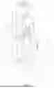
FIG. 1 is a perspective view the connection of the present invention.
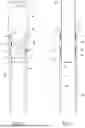
FIG. 2 is a side elevation view of one embodiment of the connector of the present invention.
FIG. 3 is a side elevation view of one embodiment of the connector of the present invention.
FIG. 4 is a front elevation view of one embodiment of the connector of the present invention.
FIG. 5 is a front elevation view of one embodiment of the connector of the present invention.
FIG. 6 is a top plan view of the connector of the present invention.
FIG. 7 is a bottom plan view of the connector of the present invention.
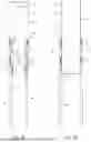
FIG. 8 is a side elevation view of one embodiment of the connector of the present invention.
FIG. 9 is a front elevation view of one embodiment of the connector of the present invention.
FIG. 10 is a side elevation view of one embodiment of the connector of the present invention.
FIG. 11 is a front elevation view of one embodiment of the connector of the present invention.
FIG. 12 is a side elevation view of one embodiment of connector of the present invention.
FIG. 13 is front elevation view of one embodiment of the connector of the present invention.
DETAILED DESCRIPTION OF THE INVENTION
As shown in FIG. 1, the present invention is a building connection 1 including a first structural member 2, a second structural member 3, and a connector 4 that receives the first end portion 5 of the first structural member 2. The connector 4 has a plurality of anchor members 6 that are received in the second structural member 3. A plurality of separate fasteners 7 attach the connector to the first structural member 2.
The first structural member 2 includes a bottom end 25 that is generally flat, a first side face 28 that is substantially planar, and an opposed second side face 29 that is substantially planar. The bottom end 25 has a width 26, as shown in Fig XX.
The second structural member 3 includes an upper surface 36 that supports the first structural member 2. The upper surface 36 is generally flat.
The connector 4 includes first and second side members 8 and 9. The first and second side members preferably do not extend into the second structural member 3. The first side member 8 is attached to the first side face 28 of the first structural member 2, and the second side member 9 is attached to the second side face 29 of the first structural member 2. The first and second side members are generally plate-like members that closely interface with the first and second side faces 28 and 29 of the first structural member. Preferably, separate fasteners 7 connect the two side members 8 and 9 of the connector 4 to the first structural member 2. The plurality of fasteners 7 are preferably mechanical fasteners that are self-drilling wood screws, but other types of screws, or nails or bolts may be used. The side members 8 and 9 may also be attached to the first structural member 2 using chemical bonds or adhesives.
The connector 4 includes a base member 10 located between the bottom end 25 of the first structural member 2 and the upper surface 36 of the second structural member 3. The base member 10 is substantially similar in width to the width 26 of the bottom end 25 of the first structural member 2.
Preferably, the first structural member 2 is received between the side members 8 and 9 of the connector 4, and the bottom end 25 of the first structural member 2 rests on a bearing surface 11 of the base member 10. The bearing surface 11 of the base member is preferably generally flat. Preferably, the base member 10 has a generally flat lower surface 12 that rests on the upper surface 36 of the second structural member 3.
The anchor members 6 are restrained by the second structural member 3. The anchor members 6 include lower portions 65 that are embedded in the second structural member 3. The anchor members 6 include upper portions 66 that extend above the second structural member 3 and are attached to the either the first or second side members 8 or 9. The first and second side members 8 and 9 are preferably formed with inward faces 38 and 39 that interface with the first and second side faces 28 and 29 of the first structural member 2 and outer faces 48 and 49. The outer face 48 of the first side member 8 is connected to the upper portions 66 of one or more of the anchor members 6, and the outer face 49 of the second side member 9 is connected to upper portions 66 of one or more of the anchor members 6.
Preferably, the first and second side members 8 and 9 and the base member 10 are formed from a single-piece of sheet metal into a channel-shaped portion 13. Preferably, the channel-shaped portion 13 of the connector 4 is cold-formed from a single piece of sheet steel. The first side member 8 is preferably formed with a bottom edge 58 and the second side member 9 is formed with a bottom edge 59 and the base member 10 connects to the first and second side members 8 and 9 at the bottom edges 58 and 59 such that the first and second side members 8 and 9 extend upwardly from the base member 10 and are not received in the second structural member 3.
The anchor members 6 are made from steel and are attached to the first and second side members 8 and 9 by welds 14. The preferred welds are flare-bevel groove welds 14. The anchor members 6 are preferably elongated members that have top ends 61. The top ends 61 of the anchor members 6 preferably extend to a middle portion 44 of the first or second side member 8 or 9. Each of the first and second side members 8 and 9 is also formed with an upper portion 46 that is disposed above the middle portion of the first or second side member 8 or 9. The first side member 8 of the channel-shaped portion 13 has an upper end 18 and the second side member 9 of the channel-shaped portion 13 has an upper end 19. The top ends 61 of the anchor members are spaced from the upper ends 18 and 19 of the first and second side members 8 and 9.
In the preferred embodiments, two anchor members 6, consisting of a left anchor member 62 and a right anchor member 63 attach to each side member 8 or 9 of the connector 4. Preferably the left anchor member 62 is closely spaced with a left side 42 of the first or second side member 8 or 9 of the connector 4, and the right anchor member 63 is closely spaced with a right side 43 of the first or second side member 8 or 9 of the connector 4.
A first plurality of fastener openings 15 in each of the first and second side members 8 and 9 that receive separate fasteners 7 are disposed between the upper portion 66 of the left anchor member 62 and the upper portion 66 of the right anchor member 63. The first plurality of fastener openings 15 in each of the first and second side members 8 and 9 that receive separate fasteners 7 are also disposed between the top ends 61 of the anchor members 6 and the bottom edges 58 and 59 of the first and second side members 8 and 9. In some embodiments of the present invention, the first plurality of fastener openings 15 has four such openings that receive separate fasteners 7, and in other embodiments of the present invention, the first plurality of fastener openings 15 has five such openings that receive separate fasteners 7.
A second plurality of fastener openings 16 in each of the first and second side members 8 and 9 that receive separate fasteners 7 are disposed in the upper portions 45 of the first and second side members 8 and 9 above the middle portions of 44 of the first and second side members. The second plurality of fastener openings 16 is disposed closer to the upper ends 18 or 19 of the first or second side members 8 or 9 than they are to the top ends 61 of the anchor members 6. In some embodiments of the present invention, the second plurality of fastener openings 16 has four such openings that receive separate fasteners 7, and in other embodiments of the present invention, the first plurality of fastener openings 15 has five such openings that receive separate fasteners 7.
In some embodiments, a third plurality of fastener openings 17 in each of the first and second members 8 and 9 that receive separate fasteners 7 are disposed in the middle portion 44 of the first and second side members 8 and 9 and above the top ends 61 of the anchor members 6 and closer to the top ends 61 of the anchor members 6 than they are to the upper end 18 of the first side member 8 or the upper end 19 of the second side member 9. In the preferred embodiment where the third fastener openings 17 are present there are two such fastener openings 17 and one of the fastener openings 17 is placed in alignment with the left anchor member 62 and one of the fastener openings 17 is placed in alignment with the right anchor member 63.
In the preferred embodiments the welds 14 that attach the anchor members 6 to the first and second side members 8 and 9 are generally 2 inches long. When the anchor members 6 are attached to the first and second side members 8 and 9, each anchor member 8 has a left side and an opposed right side when the side members 8 or 9 are viewed face on, and if more than one weld 14 attaches an anchor member 6 on either the left or right side of the anchor member, the welds are preferably spaced at least 6 inches apart.
As shown in FIG. 2, in one preferred embodiment of the connector 4, the left anchor member 62 is attached to the first side member 8 with two welds 14 on the left side of the left anchor member 62. The upper weld 14 of the two welds 14 extends downwardly from the top end 61 of the left anchor member 62 on the left side of the left anchor member 62. The lower weld 14 of the two welds 14 is disposed close to the bottom edge 58 or first side member 8. The left anchor member 62 is also attached with a weld 14 on the right side of the left anchor member 62 that is disposed generally centered between the upper and lower welds 14 on the left side of the left anchor member 62. As is also shown in FIG. 2, in one preferred embodiment of the connector 4, the right anchor member 63 is attached to the first side member 8 with two welds 14 on the right side of the right anchor member 63. The upper weld 14 of the two welds 14 extends downwardly from the top end 61 of the right anchor member 63 on the right side of the right anchor member 63. The lower weld 14 of the two welds 14 is disposed close to the bottom edge 58 of the first side member 8. The right anchor member 63 is also attached with a weld 14 on the left side of the right anchor member 63 that is disposed generally centered between the upper and lower welds 14 on the right side of the right anchor member 63.
As shown in FIG. 3, in one preferred embodiment of the connector 4, the left anchor member 62 is attached to the first side member 8 with two welds 14 on the right side of the left anchor member 62. The upper weld 14 of the two welds 14 extends downwardly from the top end 61 of the left anchor member 62 on the right side of the left anchor member 62. The lower weld 14 of the two welds 14 is disposed close to the bottom edge 58 or first side member 8. The left anchor member 62 is also attached with a weld 14 on the left side of the left anchor member 62 that is disposed generally centered between the upper and lower welds 14 on the right side of the left anchor member 62. As is also shown in FIG. 2, in one preferred embodiment of the connector 4, the right anchor member 63 is attached to the first side member 8 with two welds 14 on the left side of the right anchor member 63. The upper weld 14 of the two welds 14 extends downwardly from the top end 61 of the right anchor member 63 on the left side of the right anchor member 63. The lower weld 14 of the two welds 14 is disposed close to the bottom edge 58 of the first side member 8. The right anchor member 63 is also attached with a weld 14 on the right side of the right anchor member 63 that is disposed generally centered between the upper and lower welds 14 on the left side of the right anchor member 63.
As shown in FIG. 10, in one preferred embodiment of the connector 4, the left anchor member 62 is attached to the first side member 8 with two welds 14 on the left side of the left anchor member 62. The upper weld 14 of the two welds 14 extends downwardly from the top end 61 of the left anchor member 62 on the left side of the left anchor member 62. The lower weld 14 of the two welds 14 is disposed closer to the bottom edge 58 or first side member 8. The left anchor member 62 is also attached with two welds 14 on the right side of the left anchor member 62. The upper weld 14 is disposed generally centered between the upper and lower welds 14 on the left side of the left anchor member 62. The lower weld 14 on the right side of the left anchor member 62 is disposed close to the bottom edge 58 of the first side member 8. As is also shown in FIG. 2, in one preferred embodiment of the connector 4, the right anchor member 63 is attached to the first side member 8 with two welds 14 on the right side of the right anchor member 63. The upper weld 14 of the two welds 14 extends downwardly from the top end 61 of the right anchor member 63 on the right side of the right anchor member 63. The lower weld 14 of the two welds 14 is disposed closer to the bottom edge 58 of the first side member 8. The right anchor member 63 is also attached with two welds 14 on the left side of the right anchor member 63. The upper weld 14 is disposed generally centered between the upper and lower welds 14 on the right side of the right anchor member 63. The lower weld 14 on the left side of the right anchor member 63 is disposed close to the bottom edge 58 of the first side member 8.
Preferably, the first building structural member 2 is a post for a post frame building. Preferably, the second structural member 3 is a concrete foundation 3.
Claims
We claim:1. A building connection between a first structural member and a second structural member made with a connector and separate fasteners, the connection comprising:
a. the first structural member having a first side face, an opposed second side face and a bottom end;
b. the second structural member having an upper surface that supports the first structural member;
c. the connector which receives a first end portion of the first structural member, the connector having a plurality of anchor members, the plurality of anchor members each having a lower portion and an upper portion with the lower portions of the anchors being received in and restrained by the second structural member, the connector including a first side member that is attached to the first side face of the first structural member and a second side member that is attached to the second side face of the first structural member, the connector having a base member that connects the first and second side members with the base member resting on the upper surface of the second structural member, the first and second side members being formed with inward faces that interface with the first and second side faces of the first structural member and outer faces, the outer face of the first side member being connected to the upper portions of one or more of the anchor members, and the outer face of the second side member being connected to upper portions of one or more of the anchor members; and
d. a plurality of separate fasteners attaching the first side member to the first side face of the first structural member and the second side member to the second side face of the first structural member.
2. The connection of claim 1, wherein:
the base of the connector has a width, and the width of the lower portion of the post is similar to the width of the base of the connector.
3. The connection of claim 1, wherein:
the plurality of fasteners are preferably mechanical fasteners that are self-drilling wood screws.
4. The connection of claim 1, wherein:
the bottom end of the first structural member rests on the base member.
5. The connection of claim 1, wherein:
the first and second side members and the base member are formed from a single-piece of sheet metal into a channel-shaped portion.
6. The connection of claim 1, wherein:
the side members have a plurality of fastener openings.
7. The connection of claim 1, wherein:
the first building structural member is a post for a post frame building.
8. The connection of claim 1, wherein:
the second structural member is a cementitious member.
Images & Drawings included:


Sources:
- United States Patent and Trademark Office - verify current appl. status at the USPTO↗
Recent applications in this class:
- » 20260078579 2026-03-19
UNIVERSAL ANCHOR FOR USE WITH A GRATING FRAME - » 20260015854 2026-01-15
ANCHOR PLATE FOR MASONRY AND CONCRETE AND METHOD THEREOF - » 20250250789 2025-08-07
COIL DISK ANCHOR - » 20250179791 2025-06-05
System for Tracking and Identifying Cast-In Place Anchors - » 20250129596 2025-04-24
ANCHOR FOR A CONCRETE FLOOR - » 20250092669 2025-03-20
ATTACHMENT DEVICE FOR A ROOF NAILER PANE. - » 20250012073 2025-01-09
UNIVERSAL ANCHOR FOR USE WITH A GRATING FRAME - » 20240254755 2024-08-01
STUD RAIL SYSTEMS AND METHODS FOR USE IN REINFORCED CONCRETE STRUCTURES - » 20240200324 2024-06-20
CONNECTOR FOR A MODULAR BUILDING - » 20230203803 2023-06-29
MULTI-STORY MODULAR HOUSE AND CONNECTION ASSEMBLY THEREOF