THERMALLY ISOLATED WALL ANCHOR
US20260185348A1
2026-07-02
19/412,541
2025-12-08
Smart Summary: A new type of wall anchor helps keep the temperature stable between the inside and outside parts of a wall. It has a strong body that holds everything together. There is a support block that surrounds a plate, which helps with stability. Additionally, a connection bar block is placed around a bar that connects different parts of the anchor. This design helps improve energy efficiency by reducing heat transfer through the wall. 🚀 TL;DR
Abstract:
A wall anchor provides thermal isolation between an inner wythe and an outer wythe of a cavity wall. The wall anchor includes a structural body. A support block is about a support plate of the structural body and a connection bar block is about a connection bar of the structural body.
Assignee:
- Hohmann & Barnard, Inc. 17 🇺🇸 Hauppauge, NY, United States
Applicant:
Interested in similar patents?
Get notified when new applications in this technology area are published.
Classification:
E04B1/4185 » CPC main
Constructions in general; Structures which are not restricted either to walls, e.g. partitions, or floors or ceilings or roofs; Connections for building structures in general; Separate connecting elements; Connecting devices specially adapted for embedding in concrete; Masonry wall ties for cavity walls with both wall leaves made of masonry
E04B1/7616 » CPC further
Constructions in general; Structures which are not restricted either to walls, e.g. partitions, or floors or ceilings or roofs; Insulation or other protection; Elements or use of specified material therefor; Heat, sound or noise insulation, absorption, or reflection . Other building methods affording favourable thermal or acoustical conditions, e.g. accumulating of heat within walls specifically with respect to heat only comprising a prefabricated insulating layer, disposed between two other layers or panels in combination with an air space with insulation-layer locating devices combined with wall ties
E04B1/41 IPC
Constructions in general; Structures which are not restricted either to walls, e.g. partitions, or floors or ceilings or roofs; Connections for building structures in general; Separate connecting elements Connecting devices specially adapted for embedding in concrete
E04B1/76 IPC
Constructions in general; Structures which are not restricted either to walls, e.g. partitions, or floors or ceilings or roofs; Insulation or other protection; Elements or use of specified material therefor; Heat, sound or noise insulation, absorption, or reflection . Other building methods affording favourable thermal or acoustical conditions, e.g. accumulating of heat within walls specifically with respect to heat only
Description
CROSS-REFERENCE TO RELATED APPLICATIONS
The present application claims priority to U.S. Provisional Patent Application Ser. No. 63/739,172 filed on Dec. 27, 2024, the contents of which are hereby incorporated by reference in its entirety
FIELD OF THE DISCLOSURE
The present disclosure relates to a wall anchor, and more particularly, to a wall anchor for veneer or facade mounting that provides thermal isolation between an inner wythe and an outer wythe of a cavity wall.
BACKGROUND
Wall anchors form a part of a mounting system that bridge an internal cavity of a wall between an inner wythe and an outer wythe. Wall anchors secure to the inner wythe and a tie, frequently a wire anchoring tie, connects the wall anchor to the outer wythe constructed as a veneer. In a brick masonry or stone veneer construction, the tie is embedded in the mortar bed joint between adjacent bricks or stones.
Various wall anchors and mounting systems are known in the field, including, but not limited to, the following earlier patent disclosures by the Applicant, the contents of each of which are hereby incorporated by reference in their entireties.
U.S. Pat. No. 7,325,366 entitled, “Snap-In Wire Tie,” discloses a seismic construction system for a cavity wall.
U.S. Pat. No. 8,613,175 entitled, “High-Strength Pintles and Anchoring Systems Utilizing the Same,” discloses a high-strength ribbon pintle and cavity wall anchoring system.
U.S. Pat. No. 8,833,003 entitled, “High-Strength Rectangular Wire Veneer Tie and Anchoring Systems Utilizing the Same,” discloses a high-strength rectangular pintle veneer tire and cavity wall anchoring system.
U.S. Pat. No. 9,080,327 entitled, “Thermally Coated Wall Anchor and Anchoring Systems with In-Cavity Thermal Breaks” discloses a thermally-isolating wall anchors and anchoring systems.
The internal cavity of the wall may be filled with insulation and/or provide an air passage for environmental control. The mounting system of the tie and wall anchor, however provide a thermal bridge from the interior of the outer wythe, across the cavity and any filling contents therein, into the inner wythe, particularly when fasteners for the wall anchors are additionally considered. This thermal bridge provides a path for heat transfer, resulting in a less thermally efficient building construction. Therefore, solutions to reduce thermal bridging are desired to lead to improved building efficiency.
SUMMARY
Various embodiments of the present disclosure provide examples of wall anchors for use in building construction. A wall anchor may include a structural body that includes a support plate, extension arms extending away from the support plate, and a connection bar extending between the ends of the extension arms opposite the support plate.
A wall anchor includes a structural body that has a support plate, extension arms extending away from the support plate, and a connection bar extending between the ends of the extension arms opposite the support plate. A support plate block surrounds the support plate. There is a first aperture through the support plate and a second aperture through the support plate block, with the second aperture located radially interior to the first aperture and having a smaller diameter than the first aperture. A connection bar block surrounds the connection bar, and there is a third aperture through the connection bar and a fourth aperture through the connection bar block, with the fourth aperture located interior to the third aperture and having a smaller area than the third aperture.
The wall anchor may also have a fifth aperture through the connection bar and a sixth aperture through the connection bar block, with the sixth aperture having a smaller area than the fifth aperture and being located interior to the fifth aperture. The extension arms may include a first extension arm and a second extension arm, with the third aperture centered on a length axis of the first extension arm and the fourth aperture centered on a length axis of the second extension arm. The third aperture may have a first major axis larger than a first minor axis, and the fourth aperture may have a second major axis larger than a second minor axis, with the first major axis and first minor axis both larger than the second major axis and second minor axis. The ratio of the first major axis to the first minor axis may be larger than the ratio of the second major axis to the second minor axis. The support plate block and the connection bar block may be over-molded around the support plate and connection bar, respectively, and both may be made of thermoplastic. The extension arms may extend perpendicularly from a lower edge of the support plate, and an open interior may be defined by the support plate, extension arms, and connection bar.
The third aperture may be centered on a length axis of a first extension arm, and the fourth aperture may be centered on the length axis of the first extension arm. The third and fourth apertures may be centered along a widthwise axis of the connection block, or the fourth aperture may be offset from the length axis of the first extension arm. The anchor may also have a seal gasket secured to a back side of the support block, with the back side being opposite the connection block. The seal gasket may cover an area of the second aperture and may be made of a material with a lower durometer than the material of the support plate block. The seal gasket may be secured to the support plate block by adhesive or may be co-molded to the support plate block.
Additionally, the wall anchor may have an insulation washer with a pair of arms defining a slot between them, where the slot is configured to receive a portion of the connection bar block or a portion of the extension arms at a location between a center point of the fourth aperture and the support plate block. The anchor may also include a veneer tie with a portion of the veneer tie inserted through the third and fourth apertures, with insulation positioned between the support plate block and the veneer tie and the insulation washer positioned between the veneer tie and the insulation.
BRIEF DESCRIPTION OF THE DRAWINGS
FIG. 1 is a perspective view of an example of a cavity wall structure within which the disclosed wall anchors may be used.
FIG. 2 is a perspective view of an example of a wall anchor.
FIG. 3 is a sectional view taken along line 3-3 of FIG. 2.
FIG. 4 is a sectional view taken along line 4-4 of FIG. 2.
FIG. 5 is a sectional view taken along line 5-5 of FIG. 2.
FIG. 6 is a perspective view of an example of an insulation washer.
FIG. 7 is a perspective view of an example of a cavity wall structure using an example of the wall anchor.
DETAILED DESCRIPTION
While the present disclosure may be implemented in various forms, embodiments are disclosed herein with the understanding that such disclosure is to be considered exemplification and is not intended to limit the disclosure to the specific embodiments illustrated.
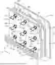
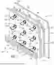
FIG. 1 depicts a perspective view of an example of a cavity wall structure 100 with an interior wythe 102 having opposing facings 104 of wallboard. Wall anchors 106 (which in the depiction of FIG. 1 are not the ones as described herein, but which the presently disclosed wall anchors can replace with improved functionality described herein) are secured through the facing 104 into the interior wythe 102, and, for example, into a vertical structural channel 108 of the interior wythe 102. The wall anchors 106 extend into a cavity 110 of the wall structure 100 between the interior wythe 102 and an exterior wythe 112, exemplarily in the form a veneer 114 constructed of facing brick 116 or stone connected by masonry bed joints 118.
The wall anchor 106 and a wire tie member 122 together form a tie system 120. The wire tie member 122 connects to the wall anchor 106. The wire tie member 122 extends across the cavity 110 and is embedded within the masonry bed joints 118 of the veneer 114.
FIG. 2 depicts a perspective view of an example of the wall anchor 200 of the present disclosure. As described herein with respect to FIG. 7, the wall anchor 200 may be used in a similar wall structure 100 as shown in FIG. 1, while replacing the wall anchor 106. FIG. 3 is a sectional view taken along line 3-3 of FIG. 2. FIG. 4 is a sectional view taken along line 4-4. FIG. 5 is a sectional view taken along line 5-5 of FIG. 2. Taken as a whole, these figures depict an example of the presently disclosed wall anchor 200. The wall anchor 200 is constructed of a structural body 202. The structural body 202 is exemplarily stainless steel. In further examples, the structural body 202 may be formed of a unitary piece of stainless steel shaped by punching and bending to the structure as described herein. The structural body 202 may be formed of other manufacturing or machining methods and may further be constructed of multiple interconnected pieces, while remaining within the scope of the present disclosure. The structural body 202 includes a support plate 204 that is exemplarily rectangular. The support plate 204 is connected to extension arms 208 which exemplarily extend perpendicularly from the support plate 204. The structural body further includes a connection bar 210 that extends between the ends of the extension arms 208 opposite the support plate 204.
The support plate 204 extends in a generally vertical dimension between a lower edge 203 and an upper edge 205. The support plate 204 may include chamfered corners 209 between the respective side edges 211 and the upper edge 207. The corners 209 may alternatively be rounded or other shapes of the corners will be recognized from the present disclosure. In examples, a corner rather than a 90 degree bend may create additional material and strength for the support plate block 216 described in further detail herein. The support plate 204 further includes at least one fastener aperture 206 therethrough. While FIG. 2 depicts a single fastener aperture 206, it will be recognized that the support plate 204 may include more than one fastener aperture 206. The at least one fastener aperture 206 is dimensioned, as described in further detail herein, to receive a fastener (not depicted) therethrough to secure the wall anchor 200 to the inner wythe (FIG. 1).
Extension arms 208 extend from the lower edge 203 of the support plate. The extension arms are perpendicular, or generally perpendicular, to the support plate 204. Generally perpendicular may mean to be within an expected tolerance of perpendicular suitable for the commercial use and purpose of the wall anchor 200 as described herein. As noted above, when the structural body 202 is a unitary construction, the extension arms 208 meet the support plate 204 at a corner 217, the corner may be formed of a rounded bend from the plane of the support plate 204 to the plane of the extension arms 208. As exemplarily shown in FIG. 4, a punching and bending construction of the structural body 202 may also form a protrusion 215 of the support plate 204 between the extension arms 208 at the corners 217. In examples, wall anchors 200 may be provided with a variety of lengths of extension arms 208 so as to accommodate a variety of sizes of wall cavities 110 (FIG. 1). As will be discussed in further detail herein, the length of the extension arms 208 may be dimensioned at least in part based upon a thickness of insulation to be positioned between the wallboard 104 and the veneer 112.
A connection bar 210 extends between the two extension arms 208 at ends of the extension arms 208 opposite the support plate 204. The connection bar 210 extends in the same plane as the extension arms 208. The spaced apart extension arms 208 and the connection bar 210 define an open interior 214 of the wall anchor 200. As previously noted, the open interior 214 may be stamped out from a unitary piece of stainless steel, defining the support plate 204, extension arms 208, and the connection bar 210 therefrom. The connection bar 210 includes two tie apertures 212 therethrough. The tie apertures 212 may be centered, or generally centered to a lengthwise axis (L) of a respective extension arm 208. The tie apertures 212 may also be centered or generally centered to a widthwise axis of the connection bar 210. As will be described in further detail below, the tie apertures 212 may also be positioned relative to widthwise axis (W) of the connection bar block 220. The tie apertures 212 are exemplarily oblong with a minor axis in the direction of the lengthwise axis (L) of the respective extension arm 208, and a major axis perpendicular to that, in the direction of the widthwise axis (W) of the connection bar block 220 extending between the extension arms 208. In a non-limiting example, the minor axis is 0.485 inch and the major axis is 0.563 inch. It will be recognized that in other examples, the tie apertures 212 may be circular.
The wall anchor 200 includes a support plate block 216 that surrounds the support plate 204. The support plate block 216 is exemplarily constructed as an over mold of thermoplastic material. As a further example, the support plate block 216 is constructed of nylon 6 material (e.g. UL94 nylon). The support plate block 216 exemplarily extends 0.125 in outwards from the support plate 204 in the width dimension, and exemplarily extends 0.085 in exterior of the support plate 204 in the thickness dimension. Like the support plate 204, the support plate block 216 includes at least one fastener aperture 218. The support plate block 216 includes a matching number and position of fastener apertures 218 as the support plate includes fastener apertures 206. The fastener aperture 218 through the support plate block 216 has a smaller diameter than the fastener aperture 206 through the support plate 204. In a non-limiting example, a diameter of the fastener aperture 218 may be between about 5-15% smaller than a diameter of the fastener aperture 206. In a further non-limiting example, the fastener aperture 206 may have a diameter of 0.313 in, while the fastener aperture 218 has a diameter of 0.281 in. In an example, the fastener aperture 218 may be concentric to the fastener aperture 206.
In examples, the support plate 204 is thus encased within the support plate block 216, including an inside circumference 213 of the fastener aperture 218 that is interior of the fastener aperture 206. This creates a barrier of the support plate block material between any fastener received within the fastener apertures 206, 218 and the support plate 204. The support plate block 216 further extends about the lower edge 203, the upper edge 205 and side edges 211 of the support plate 204. In examples, the aforementioned corners 209 which are exemplarily chamfered or rounded, provide an additional volume of continuous material for the support plate block 216 beyond the corners 209 of the support plate 204 which may provide strength and/or durability to the support plate block 216. The inside circumference 213 of the
The support plate block 216 may further include a seal gasket 230 secured to a back side 232 of the support plate block 216, the back side 232 being the side further away from the connection bar 210. The seal gasket 230 may be a separate component that may be constructed of silicone or other polymer material and may be secured to the back side 232 of the support plate block 216. The seal gasket 230 may be applied as liquid or flowable state and may be dried or cured to form an ambiently stable structure. If curing is used, such curing may exemplarily include, but is not limited to chemical, light, or heat curing. In other examples, the seal 230 may be secured to the support plate block 216 with adhesive. In an example of a seal gasket 230 secured to the support plate block 216 by a secondary process, including but not limited to the ones noted above, the seal gasket 230 may be constructed of ethylene propylene diene monomer (EPDM) rubber. EPDM provides a non-limiting example of a material for the seal gasket 230 with a Shore A hardness between 30-90, other suitable materials will be recognized based upon this disclosure.
In a still further example, the seal gasket 230 is co-molded with the support plate block 216 in position around the support plate 204. The seal gasket 230 may thus be made of a suitable thermoplastic for co-molding. In an example, however, the seal gasket 230 is constructed of a lower durometer material than the material of the support plate block 216. As discussed above, the support plate block 216 may be constructed of nylon 6, which exemplarily has a Shore A hardness of 120. The material for the seal gasket 230 may exemplarily be a thermoplastic elastomer (TPE) which exemplarily has a Shore A hardness between 30-90, between 50-80, or between 60-70. The TPE material and specific hardness thereof may be selected to be compatible with the support plate block substrate. The seal gasket 230 exemplarily extends across the entire area of the back side 232 of the support plate block 216. The seal gasket 230 further extends across the surface area of the fastener aperture 218. In examples, the comparative softness of the material of the seal gasket 230 forms a flexible and airtight seal between the wall anchor 200 and the facing 104. Additionally, the seal gasket 230 deforms around a fastener secured through the aperture 218 creating an airtight seal about the fastener into the facing 104. This creates a further barrier against air infiltration along the fastener.
The wall anchor 200 further includes a connection bar block 220. The connection bar block 220 surrounds the connection bar 210. The connection bar block 220 is exemplarily constructed as an over mold of thermoplastic material. As a further example, the connection bar block 220 is constructed of nylon 6 material. The connection bar block 220 extends about some or all of the connection bar 210. The connection bar block 220 exemplarily extends 0.125 in outwards from the connection bar 210 in the width dimension, and exemplarily extends 0.085 in exterior of the connection bar 210 in the thickness dimension. While in some examples, the connection bar block 220 extends about the connection bar 210 in all directions with only the extension arms 208 extending exterior of the connection bar block 220, as FIGS. 2 and 5 exemplarily show an example of an interior edge of the connection bar 210 extending exterior of an interior side of the connection bar block 220.
Like the connection bar 210, the connection bar block 220 includes two tie apertures 222. The tie apertures 222 are exemplarily smaller in cross-sectional area than the tie apertures 212. In examples, the tie apertures 222 are also oblong with a similarly-oriented major and minor axes. However, in other examples, the tie apertures 222 may be circular. In a still further example, the tie apertures 222 are oblong, but to a lesser degree than the tie apertures 212. In an example, the major axis of the tie aperture 222 is 0.375 in and the minor axis of the tie aperture 222 is 0.354 in. In other examples, the tie aperture 222 may be circular and have diameters between about 0.35 in. and 0.375 in. In still further examples, a cross-sectional area of the tie aperture 222 may be between 40-60% of the cross-sectional area of the tie aperture 212. Additionally, the major axis and the minor axis of the tie aperture 222 is less than a respective major axis and minor axis of the tie aperture 212. It will be recognized that the tie aperture 222, being smaller than the tie aperture 212 is located within the outer perimeter of the tie aperture 212.
The tie aperture 212 and the tie aperture 222 are exemplarily centered on the widthwise axis (W) of the connection bar block 220, although in other examples the tie apertures 212, 222 are centered on an axis of the connection bar 210. The tie apertures 212, 222 may be located in other positions through the connection bar 210 and connection bar block 220 as well. The tie aperture 222 may be centered within the tie aperture 212 or may be offset to one side or the other within the tie aperture 212. In the example provided in FIG. 5, the center of the tie aperture 222 is exteriorly offset in the widthwise dimension from the center of the tie aperture 212, while the tie aperture 222 is on the same widthwise axis (W) of the connection bar block 220, thus aligning the tie apertures 212, 222 in the lengthwise direction. In examples, the connection bar 210 is thus encased within the connection bar block 220, including an inside circumference 223 of the tie aperture 222 that is interior of the tie aperture 212. This creates a barrier of the support plate block material between any veneer tie received within the tie apertures 212, 222 and the support plate connection bar 210.
The wall anchor 200 as disclosed herein provides improved functionality and thermal barrier over existing anchor solutions, including those using coatings or gaskets between components. The support plate block 216 and the connection bar block 220 exemplarily are dimensioned to locate the nylon material at the regions of contact between the wall anchor 200 and subsequent components of a wall system, providing increased thickness of insulative material at these points of contact. Either between the wall anchor 200 to the veneer tie or to the inner wythe. Additionally, because the wall anchor 200 uses a construction of multiple components, the structural body 202 of stainless steel provides strength and rigidity to the wall anchor and provides additional fire resistance in the event of a fire in the wall cavity, retaining the veneer to the structure compared to a monolithic polymer design. The wall anchor 200 exemplarily uses a single fastener aperture 218 to minimize air barrier penetrations by the fastener received therethrough. The support plate block 216 further provides thermal isolation between the back of the support plate 204 and the interior wythe and also between the fastener (not depicted and any of the metal material of the support plate. The fastener aperture 218 may further deform and provide a seal about the fastener further limiting air infiltration at this location.
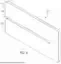
Additionally, the connection bar block 220 further provides a retention ledge 225 to hold an insulation washer 224 in place, providing further thermal isolation to the system. FIG. 6 depicts and example of the insulation washer 224. FIG. 7 depicts an example of the wall anchor 200 in use with and optionally with the insulation washer 224. The insulation washer 224 is exemplarily constructed of high impact PVC. The insulation washer 224 includes a pair of arms 226 that define a slot 228 therebetween. In use, insulation 124 is disposed in the region defined between the facing 104 and the veneer tie 122. In further use, the wall anchor 200 is secured to the facing 104 and the insulation is positioned between the support plate block and the veneer tie 122, and more specifically between the support plate block 216 and a center point of the apertures 222. The insulation washer 224 is secured to the wall anchor 200 between the insulation 124 and the veneer tie 122. A portion of the wall anchor 200 is received within the slot 228. The insulation washer 224 provides an additional barrier between the veneer tie 122 and the insulation 124, while also, in some examples placing additional retentive force on the veneer tie 122 in a direction away from support plate block 216 to seat and retain the veneer tie 122 within the tie apertures 222. This may remove any dimensional slop between the veneer tie 122 and the tie apertures 222, more securely retaining the veneer tie 122 to the wall anchor. In examples, the connection bar block 220 is received within the slot 228, while in other examples, the extension arms 208 may be received within the slot 228. In either example, the slot 228 may be dimensioned such as to have a resilient fit with the intended structure to be received within the slot 228.
In the present disclosure, the words “a” or “an” are to be taken to include both the singular and the plural. Conversely, any reference to plural items shall, where appropriate, include the singular. All percentages are percentages by weight, unless otherwise noted.
It will also be appreciated by those skilled in the art that the relative directional terms such as sides, upper, lower, top, bottom, rearward, forward and the like are for explanatory purposes only and are not intended to limit the scope of the disclosure.
Citations to a number of references are made herein. The cited references are incorporated by reference herein in their entireties. In the event that there is an inconsistency between a definition of a term in the specification as compared to a definition of the term in a cited reference, the term should be interpreted based on the definition in the specification.
In the above description, certain terms have been used for brevity, clarity, and understanding. No unnecessary limitations are to be inferred therefrom beyond the requirement of the prior art because such terms are used for descriptive purposes and are intended to be broadly construed. The different systems and method steps described herein may be used alone or in combination with other systems and methods. It is to be expected that various equivalents, alternatives, and modifications are possible within the scope of the appended claims.
This written description uses examples to disclose the invention, including the best mode, and also to enable any person skilled in the art to make and use the invention. The patentable scope of the invention is defined by the claims and may include other examples that occur to those skilled in the art. Such other examples are intended to be within the scope of the claims if they have structural elements that do not differ from the literal language of the claims, or if they include equivalent structural elements with insubstantial differences from the literal languages of the claims.
Claims
What is claimed is:1. A wall anchor comprising:
a structural body comprising a support plate, extension arms extending away from the support plate, and a connection bar extending between the ends of the extension arms opposite the support plate;
a support plate block surrounding the support plate;
a first aperture through the support plate;
a second aperture through the support plate block, wherein the second aperture is radially interior of the first aperture and a diameter of the second aperture is smaller than a diameter of the first aperture;
a connection bar block surrounding the connection bar;
a third aperture through the connection bar; and
a fourth aperture through the connection bar block, wherein the fourth aperture is located interior of the third aperture and an area of the fourth aperture is smaller than an area of the third aperture.
2. The wall anchor of claim 1, further comprising a fifth aperture through the connection bar and a sixth aperture through the connection bar block, wherein an area of the sixth aperture is smaller than an area of the fifth aperture and the sixth aperture is located interior of the fifth aperture.
3. The wall anchor of claim 2, wherein the extension arms comprise a first extension arm and a second extension arm and the third aperture is centered on a length axis of the first extension arm an the fourth aperture is centered on a length axis of the second extension arm.
4. The wall anchor of claim 1, wherein the third aperture comprises a first major axis larger than a first minor axis, and the fourth aperture comprises a second major axis larger than a second minor axis, wherein the first major axis is larger than the second major axis and the first minor axis is larger than the second minor axis.
5. The wall anchor of claim 4, wherein a ratio of the first major axis to the first minor axis is larger than a ratio of the second major axis to the second minor axis.
6. The wall anchor of claim 1, wherein the support plate block is over-molded around the support plate and the connection bar block is over-molded around the connection bar.
7. The wall anchor of claim 6, wherein the support plate block is a thermoplastic and the connection bar block is a thermoplastic.
8. The wall anchor of claim 1, wherein the extension arms extend perpendicularly from a lower edge of the support plate.
9. The wall anchor of claim 8, wherein an open interior is defined by the support plate, extension arms, and the connection bar.
10. The wall anchor of claim 1, wherein the third aperture is centered on a length axis of a first extension arm of the extension arms.
11. The wall anchor of claim 10, wherein the fourth aperture is centered on the length axis of the first extension arm.
12. The wall anchor of claim 10, wherein the third aperture and the fourth aperture are centered along a widthwise axis of the connection block.
13. The wall anchor of claim 10, wherein the fourth aperture is offset from the length axis of the first extension arm.
14. The wall anchor of claim 1, further comprising a seal gasket secured to a back side of the support block, the back side of the support block being a side opposite of the connection block.
15. The wall anchor of claim 14, wherein the seal gasket covers an area of the second aperture.
16. The wall anchor of claim 15, wherein the seal gasket is of a material having a lower durometer than a material of the support plate block.
17. The wall anchor of claim 15, wherein the seal gasket is secured to the support plate block by adhesive.
18. The wall anchor of claim 15, wherein the seal gasket is co-molded to the support plate block.
19. The wall anchor of claim 1, further comprising an insulation washer, the insulation washer having a pair of arms defining a slot therebetween, wherein the slot is configured to receive a portion of the connection bar block or a portion of the extension arms at a location between a center point of the fourth aperture and the support plate block.
20. The wall anchor of claim 19, further comprising a veneer tie with a portion of the veneer tie inserted through the third and fourth apertures, wherein insulation is positioned between the support plate block and the veneer tie and the insulation washer is positioned between the veneer tie and the insulation.
Images & Drawings included:


Sources:
- United States Patent and Trademark Office - verify current appl. status at the USPTO↗
Similar patent applications:
Recent applications in this class:
- » 20230349148 2023-11-02
Printed Wall Stabilizing Method and Assembly - » 20210348381 2021-11-11
Wall anchor system and washer for connecting to a veneer tie - » 20200308825 2020-10-01
Method for constructing a multi-stage block wall - » 20200102734 2020-04-02
Adjustable masonry anchor - » 20180371744 2018-12-27
Bridge for use in constructing a multi-stage block wall - » 20170159286 2017-06-08
Wall anchor with hollow body - » 20160289952 2016-10-06
Bridge systems for multi-stage walls - » 20150330069 2015-11-19
Masonry anchor - » 20150252560 2015-09-10
Thermally coated wall anchor and anchoring systems with in-cavity thermal breaks for cavity walls - » 20150059280 2015-03-05
Anchoring system having high-strength ribbon loop anchor
Recent applications for this Assignee:
- » 20240360678 2024-10-31
THERMAL BRICK SUPPORT MOUNTING BRACKET - » 20240093505 2024-03-21
DUAL-SIDED MOUNTING BRACKET - » 20230392385 2023-12-07
Rainscreen support system - » 20220243480 2022-08-04
Facade support system - » 20220170501 2022-06-02
Wall anchor system and washer for connecting to a veneer tie - » 20220018116 2022-01-20
Facade support system - » 20210238861 2021-08-05
Facade support system - » 20200001350 2020-01-02
Cold formed, dual seal anchor and method of making - » 11199108 2008-02-05
Snap-in wire tie - » 11111609 2006-02-14
Backer rod for expansion joints