ASSEMBLY METHOD FOR BATH STEPS
US20260185359A1
2026-07-02
19/398,927
2025-11-24
Smart Summary: Bath steps can be easily assembled by connecting at least two steps together. The sides of the steps have grooves that allow them to interlock securely. An interlocking member is inserted from the bottom or sides to hold the steps firmly in place. Different heights of steps can be combined to meet various needs and preferences. This design makes it simple to put together or take apart the bath steps, making them versatile for many uses. 🚀 TL;DR
Abstract:
An assembly method for bath steps, including preparing at least two bath steps, interlocking sides of the at least two bath steps to form at least two levels of steps. The present disclosure splices adjacent bath steps together by forming an interlocking slot through open grooves between the side panels, and inserting interlocking member from the bottom of the bath steps and/or the side panels into the interlocking slot to lock the adjacent side panels and/or adjacent bath steps together, which creates a stable and sturdy splice and improving the stability and support of the entire bath steps. Furthermore, steps of different heights can be freely combined to suit specific usage scenarios and user groups. It is simple and convenient to assemble and disassemble the bath steps, and the bath steps have a wide range of applications.
Applicant:
Interested in similar patents?
Get notified when new applications in this technology area are published.
Classification:
E04F11/035 » CPC main
Stairways, ramps, or like structures ; Balustrades; Handrails; Stairways; Layouts thereof characterised by the supporting structure Stairways consisting of a plurality of assembled modular parts without further support
A47K17/02 » CPC further
Other equipment, e.g. separate apparatus for deodorising, disinfecting or cleaning devices without flushing for toilet bowls, seats or covers; Holders for toilet brushes Body supports, other than seats, for closets, e.g. handles, back-rests, foot-rests; Accessories for closets, e.g. reading tables
Description
CROSS-REFERENCE TO RELATED APPLICATIONS
This application claims priority to Chinese Patent Application No. 202411951772.3 filed on December 27, 2024, which is incorporated by reference in its entirety.
TECHNICAL FIELD
The present disclosure relates to the technical field of bath steps, in particular to an assembly method for bath steps.
BACKGROUND
Existing bathtubs are too high for the elderly and children to step into directly. To facilitate access, a dedicated bath step is often installed alongside the bathtub. These bath steps are usually assembled using traditional welding methods, which makes it difficult to disassemble and store them. The welding process requires numerous tools and is complex to install. Some bath steps are factory-installed, but the number and height of the bath steps are not able to be adjusted according to actual usage needs, or the assembly and disassembly structures for those bath steps are complex, requiring specialized tools or specialized personnel, making it difficult to adapt to different scenarios and fail to meet user needs for convenience.
SUMMARY
The present disclosure provides an assembly method for bath steps, which is to place a plurality of bath steps according to actual needs, and then fixedly interlock the plurality of bath steps with interlocking members, wherein the interlocking members are interlocked with interlocking slots formed between adjacent side panels. It is convenient to assemble and disassemble the bath steps, meet the needs of users in various scenarios and enhance the user experience.
To achieve the above objectives, the present disclosure provides an assembly method for bath steps, including:
preparing at least two bath steps, interlocking sides of the at least two bath steps to form at least two levels of steps.
As a further improvement of the present disclosure, preparing each of the at least two bath steps includes:
preparing a side panel set and a tread plate, wherein the side panel set includes a left side panel and a right side panel, the left side panel and the right side panel are of equal height, and placing two ends of the tread plate on the left side panel and the right side panel respectively to form a bath step.
As a further improvement of the present disclosure, interlocking the sides of the at least two bath steps includes:
arranging the at least two bath steps adjacent to each other by interlocking the sides of the at least two bath steps vertically to ground to form at least two levels of steps, the at least two bath steps being in a gradually increasing or decreasing order of height.
As a further improvement of the present disclosure, arranging the at least two bath steps adjacent to each other by interlocking sides of the at least two bath steps vertically to ground further includes:
arranging one side panel of one bath step aligned to an adjacent side panel of an adjacent bath step;
providing an open groove on each of the side panels of one bath step and the adjacent side panel of the adjacent bath step, thereby an interlocking slot is formed when the open groove of one bath step is aligned to another open groove of the adjacent bath step;
inserting an interlocking member into a bottom of the interlocking slot to fixedly connect the side panel of one bath step and the adjacent side panel of the adjacent bath step, such that each of left end and right end of adjacent two bath steps are restrained and fixedly connected by the interlocking slot and the interlocking member to form the at least two levels of steps.
As a further improvement of the present disclosure, each of the bath steps is provided with two side ends oppositely arranged to each other, each of the two side ends is provided with a first side surface. The method further includes:
arranging the adjacent bath steps abut to each other, so that two first side surfaces of the adjacent bath steps are in contact with each other and two open grooves of the adjacent bath steps align to each other to form an interlocking slot, wherein a cross-sectional profile of the interlocking slot is in a shape of an "X"; and
inserting the interlocking member into the interlocking slot to secure adjacent side panels, thereby securing the adjacent bath steps, wherein a cross-sectional profile of the interlocking member is in a shape of an "X" that matches the cross-sectional profile of the interlocking slot.
As a further improvement of the present disclosure, each of the two side ends is further provided with a second side surface, and a support notch is provided at top of the second side surface. The tread plate includes two crossbeams arranged oppositely to each other, with an end of each of the two crossbeams placed on the support notch. The support notch also includes a limiting notch that matches a shape of a bottom of each of the two crossbeams to limit loosening when each of the two crossbeams is placed on the support notch.
As a further improvement of the present disclosure, a support plate and a pressure plate are horizontally provided on each of the two crossbeams, the support plate and the pressure plate extend inwardly from the crossbeams, and a plate is arranged between the support plate and the pressure plate.
As a further improvement of the present disclosure, a number of levels of the bath steps is in a range from two to five.
As a further improvement of the present disclosure, a height difference between adjacent bath steps of the at least two bath steps is in a range from 15 cm to 30 cm.
As a further improvement of the present disclosure, a depth of the at least two bath steps is in a range from 20 cm to 33 cm, and a width of the at least two bath steps is in a range from 55 cm to 120 cm.
Compared to existing technologies, the present disclosure has the following advantages:
Adjacent bath steps are spliced together by forming an interlocking slot through open grooves between the side panels, and inserting interlocking member from the bottom of the bath steps and/or the side panels into the interlocking slot to lock the adjacent side panels and/or adjacent bath steps together, which creates a stable and sturdy splice and improving the stability and support of the entire bath steps. Furthermore, steps of different heights can be freely combined to suit specific usage scenarios and user groups. It is simple and convenient to assemble and disassemble the bath steps, and the bath steps have a wide range of applications.
BRIEF DESCRIPTION OF THE DRAWINGS
To more clearly illustrate the technical solution, the following briefly describes the drawings required for the embodiment. Obviously, the drawings described below represent only some embodiment of the present disclosure. One skilled in the art can derive other drawings based on these drawings without inventive effort.
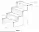
FIG. 1 is a schematic structural diagram of the present disclosure.
FIG. 2 is a schematic diagram of the connection of adjacent bath steps in one embodiment.
FIG. 3 is a schematic structural diagram of the connection between the two side panels in one embodiment.
FIG. 4 is an exploded view of the connection between the two side panels in one embodiment.
FIG. 5 is an exploded view of the connection between the side panels and the tread in one embodiment.
DETAILED DESCRIPTION
To provide a clear and complete understanding of the technical solution, the present disclosure will now be further described with reference to the following embodiment and accompanying drawings. It should be understood that the described embodiments are merely partial embodiments of the present disclosure, and all other embodiments deriving from the absence of inventive effort by persons skilled in the art are intended to fall within the scope of protection of the present disclosure.
It should be understood that, as used in this specification and the appended claims, the terms "include" and "comprising" indicate the presence of the described features, integers, steps, operations, elements, and/or components, but do not preclude the presence or addition of one or more other features, integers, steps, operations, elements, components, and/or combinations thereof.
It should also be understood that the terminology used in this specification is intended solely to describe specific embodiment and is not intended to limit the present disclosure. As used in this specification and the appended claims, the singular forms "a," "an," and "the" are intended to include the plural forms unless the context clearly indicates otherwise.
It should also be understood that, as used in this specification and the appended claims, the term "and/or" refers to and includes any and all possible combinations of one or more of the associated listed items.
One embodiment of the present disclosure provides an assembly method for bath steps. Referring to the step structure diagram shown in FIG. 1, the method includes preparing at least two bath steps 300, and interlocking sides of the at least two bath steps 300 to form at least two levels of steps.
Furthermore, preparing at least two bath steps includes preparing a side panel set 100 and a tread plate 200, wherein the side panel set 100 includes a left side panel and a right side panel 110 of equal height; placing two ends of the tread plate 200 on the left side panel and the right side panel 110 respectively and spliced them to form a bath step 300.
In some embodiments, the at least two bath steps further include side panel sets 100 of different heights and tread plates 200 of same width. The side panel sets 100 include left side panels and right side panels 110 of equal height. Two ends of the tread plates 200 are placed on the left side panels and the right side panels 110 of equal height respectively, thereby forming the at least two bath steps 300 of different heights. Each bath step of the at least two bath steps 300 is arranged adjacent to each other in a manner of gradually increasing or decreasing order of height by interlocking the sides of the at least two bath steps, thereby forming at least two levels of steps, wherein the sides of the at least two bath steps are vertically placed to ground.
Through the aforementioned method, bath steps of varying heights and numbers can be freely combined to accommodate bathtubs of varying heights. Furthermore, a height difference between the bath steps can be adjusted according to actual needs to accommodate different user groups, such as children, adults, and the elderly.
The present embodiment provides four-level bath steps based on the height of the bathtubs. In some embodiments, non-gradually ascending bath steps can be used to step up into the bathtubs from a low platform, or non-gradually descending bath steps can be used to step down into the bathtubs from a high platform, depending on actual scenarios or site requirements. This can be achieved by using a various of combination of bath steps, such as arranging ascending bath steps first and descending bath steps later (e.g., three ascending bath steps first and one descending bath step later), arranging descending bath steps first and ascending bath steps later (e.g., one decreasing bath step first and four ascending bath steps later), or arranging several same height bath steps in between. Bath steps of different heights can be interlocked adjacent to each other by interlocking the sides of adjacent bath steps according to practical needs of scenarios or site requirements. The purpose of this embodiment is to allow bath steps of different heights to be interlocked and connected through the side panel sets of the at least two bath steps, thus meeting the needs of different users or scenarios.
For a better understanding, based on the above embodiment, an alternative embodiment of the present disclosure includes the following:
As shown in FIGS. 2 and 3, one side panel of one bath step is arranged to be aligned with an adjacent side panel of an adjacent bath step.
Each of the side panels 110 are provided with an open groove 111 on a side that abuts the adjacent bath step. The open grooves 111 of adjacent two side panels align to each other to form an "X"-shaped interlocking slot 120.
An "X"-shaped interlocking member 130 is inserted into a bottom of the interlocking slot 120 to fixedly connect the adjacent two side panels, such that each of a left end and a right end of the adjacent bath steps 300 are restrained and fixedly connected by the interlocking slot 120 and the interlocking member 130 to form the at least two levels of steps.
Furthermore, referring to FIG. 4, both sides of the side panel 100 are bent twice at right angles inwardly, forming an "L"-shaped feature with a hooked side end 112. The hooked side end 112 includes a first side surface 113. A center portion of the first side surface 113 of the side end 112 is recessed to form an open groove 111. A width of an opening of the open groove 111 is smaller than a width of a groove bottom of the open groove 111.
Furthermore, as shown in FIGS. 2-4, adjacent bath steps 300 are placed abut to each other so that the two first side surfaces 113 are in contact with each other and the openings of the two open grooves 111 align to each other, forming an interlocking slot 120. The cross-sectional profile of the interlocking slot 120 is shaped like an "X".
The adjacent side panels 110 are secured by inserting an "X"-shaped interlocking member 130 into the interlocking slot 120, thereby splicing and securing the adjacent bath steps 300.
This embodiment uses an "X"-shaped interlocking slot formed by a connection between the open grooves of the adjacent side panels. The "X"-shaped interlocking member then locks the two adjacent side panels together, making the connection between the bath steps more stable and sturdier.
It should be noted that the height of the interlocking member depends on the actual height of the side panels or the size of the bath steps. This embodiment does not impose any restrictions on the height of the interlocking member. Any person skilled in the art can set the height based on actual needs. Generally, the higher the interlocking member, the more stable the connection between the two bath steps. It can generally be set to a height similar to the height of the side panel of the lowest bath step.
To enhance the stability and support between the tread plate and the side panel set, in an optional embodiment, as shown in FIGS. 4 and 5, each of the two side ends 112 is further provided with a second side surface 114, and a support notch 115 is provided at a top of the second side surface 114. The tread plate 200 includes two crossbeams 210 arranged oppositely to each other. An end of the each of the two crossbeams 210 is placed on the support notch 115. The support notch 115 also includes a limiting notch 116 that matches a shape of a bottom of each of the two crossbeams 210, in order to limit loosening when each of the two crossbeams 210 is placed on a top of the side end 112.
Furthermore, two ends of an outer side of the crossbeams 210 are both cut with joint notches 230 that match the cross-sectional profile of the side end 112. This limits position of the crossbeams 210 when the crossbeams 210 are embedded in the side end 112. The remaining portions on either side of the joint notch 230 fit neatly into the side end 112, that is, insert into outer sides of the opening of the open groove 111, which makes the outer surface of the crossbeams 210 contact to an inner surface of the side end 112, effectively enhancing the stability of the tread plate and side panel set.
Furthermore, a support plate 211 and a pressure plate 212 are horizontally provided on each of the two crossbeams 210 and extend inwardly from the crossbeams 210. A plate 220 is positioned between the support plate 211 and the pressure plate 212. When the plate 220 is inserted between the support plate 211 and the pressure plate 212, and the ends of the front and rear crossbeams are embedded in the side ends 112, the crossbeams 210 are restrained from front and rear direction by the side ends 112, which prevents the plate 220 from loosening or falling off. Reinforcing ribs 213 are also provided beneath the support plate 211 to further enhance the support of the tread plate.
In this embodiment, the joint notches 230 interact with the support notches 115 and the limiting notches 116 provided at the side ends 112, creating a direct connection between the crossbeam 210 and the side panels 110. The shapes of the support notch 115, the limiting notch 116, and the joint notch 230 provides horizontal restraint to the crossbeam 210, ensuring structural stability after splicing. After splicing is complete, side covers 240 are applied to prevent the tops of the side panels from being exposed, which is not only aesthetically pleasing, but also capable of protecting users from cut by the sharp top edges.
It should be noted that the present disclosure can also form a bath step with only one level by interlocking the side panels and the tread plate. A person skilled in the art can adjust the levels of steps according to actual usage requirements. For example, if a bathtub is relatively low, such as 30 cm, two or more steps are not necessarily required for entering and exiting the bathtub. Therefore, a bath step formed by interlocking the side panels and the tread plate according to actual circumstances also falls within the scope of protection of the present disclosure.
Obviously, the above embodiments are merely illustrative of the bath step structure and assembly method of the present disclosure and are not intended to limit the scope of protection of the present disclosure. Without departing from the spirit of the present disclosure, those skilled in the art will be able to adjust the above structure and assembly method to adapt the present disclosure to more specific application scenarios.
The present disclosure also provides another embodiment, based on the above embodiments, in which the open grooves 111 between adjacent bath steps are filled with a rubber strip for cushioning or collision prevention. The rubber strip extends downwardly from top of the open grooves 111 and extends beyond the tread plate 200 of the adjacent bath steps. The thickness of the rubber strip is greater than the depth of the open grooves 111, so that the rubber strip slightly protrudes from the grooves.
This embodiment effectively prevents the edges or borders of the open grooves 111 from injuring users or accumulating dust and debris by filling the rubber strip in the open grooves 111 at a place which is not spliced with an interlocking member. In this embodiment, the thickness of the rubber strip is slightly greater than the depth of the open grooves 111, that is, the rubber strip protrudes the first side surface 113 where the open groove 111 is located, so that it prevents friction and collision between adjacent bath steps when the bath steps are subjected to stress, providing a cushioning and collision prevention effect. It also prevents friction between bath steps, thereby preventing unusual noise and providing a quieting effect.
In a preferred embodiment, a number of levels of the bath steps is in a range from two to five, and a height difference between adjacent bath steps is in a range from 15 cm to 30 cm. A depth of the bath steps is in a range from 20 cm to 33 cm, and a width of the bath steps is in a range from 55 cm to 120 cm. Bathtubs are comfortable in a typical height from 40 cm to 60 cm. Based on this height, arranging four-level bath steps with an 18 cm height difference between adjacent bath steps provides excellent user comfort and high stability for assembling the bath steps.
The present disclosure connects adjacent bath steps by forming an interlocking slot through open grooves between the side panels, and inserting interlocking member from the bottom of the bath steps and/or the side panels into the interlocking slot to lock the adjacent side panels and/or adjacent bath steps together, which creates a stable and sturdy splice and improving the stability and support of the entire bath steps.
The above disclosure only describes one or more preferred embodiment of the present disclosure and is provided to facilitate understanding of the inventive concept of the technical solution. It does not limit the present disclosure in any other manner. Other equivalent or customary substitutions based on the features defined by the present disclosure by those skilled in the art are still within the scope of the present disclosure.
Claims
I claim:1. An assembly method for bath steps, comprising:
preparing at least two bath steps, interlocking sides of the at least two bath steps to form at least two levels of steps.
2. The assembly method for bath steps according to claim 1, wherein preparing each of the at least two bath steps comprises:
preparing a side panel set and a tread plate, the side panel set comprising a left side panel and a right side panel, the left side panel and the right side panel are of equal height; and
placing two ends of the tread plate on the left side panel and the right side panel respectively to form a bath step.
3. The assembly method for bath steps according to claim 2, wherein interlocking the sides of the at least two bath steps comprises:
arranging the at least two bath steps adjacent to each other by interlocking the sides of the at least two bath steps vertically to ground to form at least two levels of steps, the at least two bath steps being in a gradually increasing or decreasing order of height.
4. The assembly method for bath steps according to claim 3, wherein arranging the at least two bath steps adjacent to each other by interlocking the sides of the at least two bath steps vertically to ground further comprises:
arranging one side panel of one bath step aligned to an adjacent side panel of an adjacent bath step;
providing an open groove on each of the side panels of one bath step and the adjacent side panel of the adjacent bath step, thereby an interlocking slot is formed when the open groove of one bath step is aligned to another open groove of the adjacent bath step; and
inserting an interlocking member into a bottom of the interlocking slot to fixedly connect the side panel of one bath step and the adjacent side panel of the adjacent bath step, such that each of left end and right end of adjacent two bath steps are restrained and fixedly connected by the interlocking slot and the interlocking member to form the at least two levels of steps.
5. The assembly method for bath steps according to claim 4, wherein each of the bath steps is provided with two side ends oppositely arranged to each other, each of the two side ends is provided with a first side surface, wherein arranging the at least two bath steps adjacent to each other by interlocking sides of the at least two bath steps vertical to ground further comprises:
arranging the adjacent bath steps abut to each other, so that two first side surfaces of the adjacent bath steps are in contact with each other and two open grooves of the adjacent bath steps align to each other to form an interlocking slot, wherein a cross-sectional profile of the interlocking slot is in a shape of an "X"; and
inserting the interlocking member into the interlocking slot to secure adjacent side panels, thereby securing the adjacent bath steps, wherein a cross-sectional profile of the interlocking member is in a shape of an "X" that matches the cross-sectional profile of the interlocking slot.
6. The assembly method for bath steps according to claim 5, wherein each of the two side ends is further provided with a second side surface, and a support notch is provided at a top of the second side surface;
the tread plate comprises two crossbeams arranged oppositely to each other, with an end of each of the two crossbeams placed on the support notch; and
the support notch is further provided with a limiting notch that matches a shape of a bottom of each of the two crossbeams, in order to limit loosening when each of the two crossbeams is placed on a top of the side end.
7. The assembly method for bath steps according to claim 6, wherein a support plate and a pressure plate are horizontally provided on each of the two crossbeams, the support plate and the pressure plate extend inwardly from the crossbeams, and a plate is arranged between the support plate and the pressure plate.
8. The assembly method for bath steps according to claim 1, wherein a number of levels of the bath steps is in a range from two to five.
9. The assembly method for bath steps according to claim 1, wherein a height difference between adjacent bath steps of the at least two bath steps is in a range from 15 cm to 30 cm.
10. The assembly method for bath steps according to claim 1, wherein a depth of the at least two bath steps is in a range from 20 cm to 33 cm, and a width of the at least two bath steps is in a range from 55 cm to 120 cm.
Images & Drawings included:


Sources:
- United States Patent and Trademark Office - verify current appl. status at the USPTO↗
Recent applications in this class:
- » 20260185358 2026-07-02
MODULAR CONSTRUCTION CONNECTION MECHANISM - » 20260160071 2026-06-11
PLATFORM SYSTEM - » 20260078586 2026-03-19
ROBOT-DEPLOYABLE ACCESSIBILITY SYSTEM - » 20250067056 2025-02-27
MODULAR LEVEL ACCESS STRUCTURES - » 20240344330 2024-10-17
PRECAST CONCRETE STAIRWAY CONSTRUCTION METHOD - » 20240191508 2024-06-13
MODULAR CONSTRUCTION CONNECTION MECHANISM - » 20230212859 2023-07-06
Support for raised floors with shaped base and fixing brackets - » 20220372765 2022-11-24
Modular staircase and method of constructing same - » 20220259864 2022-08-18
Fully-assembled staircase system and assembly method - » 20210396017 2021-12-23
Modular staircase systems