UNIVERSAL GROUND MOUNTING PLATE
US20260185371A1
2026-07-02
19/002,698
2024-12-27
Smart Summary: A universal ground mounting plate is designed to hold vertical poles securely. It has a base with multiple holes that can fit different types of anchors, whether for concrete or soil. Each hole is shaped to hold the anchor securely in place. The plate also has a collar that can hold poles of various sizes and has screws to keep the pole steady. This mounting plate can be used in many different situations, making it strong and adaptable for various needs. 🚀 TL;DR
Abstract:
A universal ground mounting plate for securing vertical poles is described herein. In various examples, the mounting plate comprises a base plate with a plurality of compound apertures arranged in a ring to interchangeably receive concrete anchors and earth anchors. Each aperture includes a large circular portion for anchor heads and a narrow slot portion for anchor retention. A vertically extending collar is configured to receive a pole, with setscrew receptacles positioned around the collar to secure the pole in place. The collar may be welded or integrally formed with the base plate and is designed to accommodate various pole diameters. The mounting plate provides versatility for installation on different foundations, including concrete and soil, while ensuring structural stability and adaptability to diverse applications.
Inventors:
- Ryan Tucker Silvernale 1 🇺🇸 Temecula, CA, United States
- Taqi Khawaja-Ghulam 1 🇺🇸 Princton, NJ, United States
- Craig Ells 1 🇺🇸 Brentwood, CA, United States
- Brian Eglsaer 1 🇺🇸 San Mateo, CA, United States
Assignee:
- Freedom Forever LLC 2 🇺🇸 Temecula, CA, United States
Applicant:
Interested in similar patents?
Get notified when new applications in this technology area are published.
Classification:
E04H12/2238 » CPC main
Towers; Masts or poles; Chimney stacks; Water-towers; Methods of erecting such structures; Sockets or holders for poles or posts to be placed on the ground
E04H12/22 IPC
Towers; Masts or poles; Chimney stacks; Water-towers; Methods of erecting such structures Sockets or holders for poles or posts
Description
TECHNICAL FIELD
This disclosure relates to ground mounting plates. More particularly, this disclosure relates to ground mounting plates for securing a pole in a vertical position.
BRIEF DESCRIPTION OF THE DRAWINGS
Non-limiting and non-exhaustive embodiments of the disclosure are described, including various embodiments of the disclosure with reference to the figures, in which:
FIG. 1 is a top perspective view of a universal ground mounting plate, according to one embodiment.
FIG. 2A is a bottom perspective view of the universal ground mounting plate, according to one embodiment.
FIG. 2B is a bottom perspective view of the universal ground mounting plate, according to another embodiment.
FIG. 3A illustrates a side profile view of the universal ground mounting plate, according to one embodiment.
FIG. 3B illustrates a side profile view of the universal ground mounting plate, according to another embodiment.
FIG. 3C illustrates a side profile view of the universal ground mounting plate with example dimensions, according to one embodiment.
FIG. 4 illustrates a side profile view of the universal ground mounting plate from another angle, according to one embodiment.
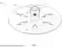
FIG. 5A is a top view of the universal ground mounting plate, according to one embodiment.
FIG. 5B is a top view of the universal ground mounting plate with example dimensions, according to one embodiment.
FIG. 6A is a perspective view of a universal ground mounting plate with a pole secured within the collar, according to one embodiment.
FIG. 6B illustrates a perspective view of the pole adjusted to a vertical position using the setscrews in the collar, according to one embodiment.
FIG. 7A illustrates the universal ground mounting plate mounted to a concrete pillar with a pole and solar panels, according to one embodiment.
FIG. 7B illustrates a close-up view of the universal ground mounting plate mounted to the concrete pillar, according to one embodiment.
FIG. 8A illustrates the universal ground mounting plate adjustably mounted to a concrete pillar via a four-post base plate set within the concrete pillar, according to one embodiment.
FIG. 8B illustrates a close-up view of the universal ground mounting plate adjustably mounted to the concrete pillar via the four-post base plate, according to one embodiment.
FIG. 9A illustrates the universal ground mounting plate adjustably mounted to a concrete pillar via a three-post base plate set within the concrete pillar, according to one embodiment.
FIG. 9B illustrates a close-up view of the universal ground mounting plate adjustably mounted to the concrete pillar via the three-post base plate, according to one embodiment.
FIG. 10A illustrates the universal ground mounting plate secured directly to the ground via three earth anchors, according to one embodiment.
FIG. 10B illustrates a close-up view of the universal ground mounting plate with a locknut of an earth anchor positioned within the large slot opening of the universal ground mounting plate, according to one embodiment.
FIG. 10C illustrates a close-up view of the universal ground mounting plate with three locknuts of earth anchors locked within the narrow slots of the universal ground mounting plate, according to one embodiment.
FIG. 11A illustrates the universal ground mounting plate secured directly to the ground via six earth anchors, according to one embodiment.
FIG. 11B illustrates a close-up view of the universal ground mounting plate secured directly to the ground via six earth anchors, according to one embodiment.
DETAILED DESCRIPTION
In the field of mounting systems for vertical poles, various approaches have been developed to secure poles to the ground. Traditional methods often involve the use of concrete foundations, where a pole is embedded directly into a poured concrete base. This approach provides stability but lacks flexibility, as it requires significant time and resources to install and is not easily adaptable to different pole sizes or ground conditions. Additionally, once installed, these concrete bases are permanent, making relocation or adjustment of the pole challenging.
Another common approach involves the use of earth anchors, which are driven into the ground to provide support for the pole. Earth anchors offer more flexibility than concrete foundations, as they can be installed and removed with relative ease. However, they may not provide the same level of stability, especially in loose or sandy soil conditions. Furthermore, earth anchors typically require specialized equipment for installation, which can increase the complexity and cost of the mounting process.
Some installations have attempted to combine the use of concrete and earth anchors to provide a more versatile solution. These installations often involve separate components for each type of anchor, requiring additional parts and assembly steps. While these installations offer some adaptability, the implementation and installation steps can be cumbersome and inefficient, as they necessitate\carrying and managing multiple components for different installation scenarios.
None of the existing approaches provide a comprehensive solution that combines the features described in this disclosure. For example, in various embodiments described herein, a universal ground mounting plate can be used to securely anchor vertical poles in various installation environments, including soil and concrete foundations. The universal ground mounting plate includes a circular base plate that integrates multiple compound apertures arranged in an equidistant pattern around a central collar. Each compound aperture includes a circular hole to allow the passage of anchor heads and a narrow slot to retain and secure the anchor heads in place. This dual-purpose aperture design supports both earth anchors and concrete anchors, enhancing installation flexibility with a single mounting plate.
In various embodiments, the central collar extends vertically from the base plate and is dimensioned to accept standard pipes, such as Schedule 40 galvanized steel poles. It is equipped with equidistantly spaced set screw receptacles, which allow for precise alignment and secure retention of the inserted pole using set screws. The collar may be welded to the base plate or flared and welded to provide additional structural integrity. Depending on the embodiment, the collar may pass through the base plate or be integrated as a single monolithic component.
The base plate may be, for example, fabricated from durable, corrosion-resistant materials such as galvanized steel or aluminum alloys, ensuring long-term reliability in outdoor environments. Specific embodiments incorporate chamfered edges on the apertures for ease of anchor installation and tapered slots to enhance anchor retention. The plate can also include adjustable mounting configurations, such as attachment to embedded base plates with leveling nuts or direct anchoring via earth anchors.
The versatile design supports secure installations of poles for applications such as solar panels, minimizing material waste and accommodating various soil conditions and load requirements. Its adaptability, structural stability, and ease of installation make it suitable for a wide range of foundational mounting scenarios.
The embodiments of the disclosure can be understood with reference to the drawings. It will be readily understood that the components of the disclosed embodiments, as generally described and illustrated in the figures herein, could be arranged and designed in a wide variety of different configurations and dimensions. Thus, the following detailed description of the embodiments of the systems and methods of the disclosure is not intended to limit the scope of the disclosure, as claimed, but is merely representative of possible embodiments of the disclosure. In addition, the steps of a method, do not necessarily need to be executed in any specific order, or even sequentially, nor do the steps need to be executed only once, unless otherwise specified.
For example, the specific dimensions of a given universal ground mounting plate may be adjusted to fit different shapes and sizes (e.g., diameters) of poles and/or have different thicknesses based on the metal used for manufacturing. In some cases, well-known features, structures, or operations are not shown or described in detail. Furthermore, the described features, structures, or operations may be combined in any suitable manner in one or more embodiments. It will also be readily understood that the components of the embodiments, as generally described and illustrated in the figures herein, could be arranged and designed in a wide variety of different configurations. For example, throughout this specification, any reference to “one embodiment,” “an embodiment,” or “the embodiment” means that a particular feature, structure, or characteristic described in connection with that embodiment is included in at least one embodiment. Thus, the quoted phrases, or variations thereof, as recited throughout this specification are not necessarily all referring to the same embodiment.
It is recognized that a wide variety of materials and manufacturing techniques may be used to fabricate the various embodiments of the universal ground mounting plates described herein. In some embodiments, the universal ground mounting plates may be a single monolithic material. In additional embodiments, multiple materials may be utilized. For example, a first material may be used for the flat plate portion, a second material may be used for the collar, and third material may be used for the setscrew receptacles. In some embodiments, the collar may be welded to the top surface of the flat base plate. In other embodiments, the flat base plate and the collar may be formed from a single monolithic piece of metal. In other embodiments, the collar may pass through a center aperture of the flat base plate. In such embodiments, the collar may be flared on the bottom side of the base plate and welded to the top and/or bottom surfaces of the base plate.
Examples of suitable materials to fabricate the various components (e.g., the base plate, the collar, and/or the setscrew receptacles) include, but are not limited to, galvanized steel, stainless steel, aluminum alloys, titanium alloys, and corrosion-resistant metal composites. The specific materials and alloys may be chosen for their durability, resistance to environmental degradation, and structural strength under load. The various embodiments of universal ground mounting plates may be manufactured using fabrication methods such as laser cutting, water jet cutting, casting, stamping, and CNC machining for precise shaping of components. Welding techniques, including MIG, TIG, and spot welding, may be employed to assemble the collar, setscrew receptacles, and base plate. Additional techniques, such as powder coating, galvanizing, or anodizing, can be applied to enhance corrosion resistance and extend the longevity of the components in outdoor environments. These processes ensure the universal ground mounting plates meet the high standards required for demanding applications.
FIG. 1 is a top perspective view of a universal ground mounting plate 100, according to one embodiment. The universal ground mounting plate 100 is used to securely mount vertical poles in various foundation types. The mounting plate 100 comprises a base plate 110 with a top surface 111, which serves as the primary structural element for interfacing with the ground or other mounting surfaces. The top surface includes a centrally positioned collar 150, which extends vertically from the base plate. The collar 150 is designed to, for example, accommodate the outer diameter of a Schedule 40 galvanized steel pipe and includes a hole 151 to receive the pipe. To ensure precise alignment and secure retention, the collar is equipped with three equidistantly spaced setscrew receptacles 152, 153, and 154, which are pre-threaded to accommodate setscrews. These setscrews apply tension against the inserted pipe, ensuring stability and vertical alignment.
The base plate 110 further features a series of apertures 175, strategically arranged in a ring pattern around the collar. Each aperture 175 is a compound design, combining a large circular portion 177 and a narrow slot portion 176. The large circular portion 177 facilitates the insertion of anchor heads, such as those of concrete anchors or earth anchors. The narrow slot 176 is used to slidably retain earth anchor heads, ensuring they are securely locked in place once installed. The mounting plate 100 can be interchangeably used to support both concrete and earth anchoring systems, enabling versatile installation on a variety of surfaces.
In some embodiments, the base plate 110 and collar 150 are constructed from corrosion-resistant materials, such as galvanized steel, to ensure durability in outdoor environments. In some embodiments, the large circular apertures 177 are chamfered to ease the insertion process of anchor heads. In some embodiments, the narrow slots 176 may feature a tapered profile to enhance the retention of earth anchors during use.
The illustrated embodiment can be used for a wide variety of mounting poles, including those used in solar panel installations, with the flexibility to support either soil or concrete foundations. The setscrew receptacles in the collar and the dual-purpose apertures in the base plate enhance the universal function of the mounting plate while maintaining structural stability and ease of installation.
FIG. 2A is a bottom perspective view of the universal ground mounting plate 200, according to one embodiment. The illustrated embodiment shows several structural features on the bottom surface 212 of the base plate 210. The base plate 210 may be constructed from a robust and corrosion-resistant material such as galvanized steel. The base plate 210 serves as the foundation for secure mounting and anchoring of vertical poles. The bottom surface 212, in various examples, is flat and reinforced to ensure stability when interfaced with various mounting surfaces, such as soil or concrete.
As previously described, the strategically arranged multiple apertures 275 are designed to accommodate both concrete anchors and earth anchors. Each aperture 275 features a compound configuration, including a circular portion 277 and an adjoining narrow slot 276. The circular portion 277 is engineered to allow easy insertion of anchor heads, whether they are for concrete or earth anchors. The narrow slot 276 extends radially from the circular portion and serves to retain earth anchor heads once they are positioned, locking them securely into place. This dual-purpose design enhances the versatility of the mounting plate, making it compatible with a variety of installation methods and environmental conditions.
The precise placement and spacing of the apertures 275 around the base plate provide for load distribution and ensure that the mounting plate maintains its structural integrity under tension. The circular portions 277 and slots 276 are dimensioned to facilitate straightforward installation while providing secure anchoring once the components are deployed. The universal mounting plate 200 is a highly adaptable solution for securing poles in both concrete pillar installations and earth-anchored installations.
FIG. 2B is a bottom perspective view of the universal ground mounting plate 200, according to another embodiment. The illustrated example embodiments include a base portion 280 of a collar (not shown in FIG. 2B, but see the collar 150 from FIG. 1). In the illustrated embodiment, the collar extends through the base plate 210, with its lower section forming the base portion 280, which is visible on the underside of the base plate 210. This through-plate configuration enhances the structural integrity of the universal mounting plate 200 by creating a direct and secure connection between the collar and the base plate 210. The base portion 280 of the collar may be welded to the underside of the base plate 210 to further reinforce the joint, ensuring the collar remains stable during use. The through-plate configuration may be used to improve axial and lateral loads, improving the useability in demanding installations, such as in solar panel ground mounts or similar applications.
FIG. 3A illustrates a side profile view of the universal ground mounting plate 300, according to one embodiment. The base plate 310 serves as the foundation for the assembly, with the collar 350 extending vertically from its top surface to receive a pole. In the illustrated example, the collar 350 is securely affixed to the base plate 310 via a weld ring 360. The weld ring 360 provides a robust connection to ensure the collar remains stable under axial and lateral loads. Additionally, the collar 350 is equipped with a set screw receptacle 353, implemented as a pre-threaded nut welded directly onto a drilled aperture in the collar 350. This welded-on nut allows for the insertion of a set screw to firmly secure a pole within the collar 350. The set screw can be adjusted to provide proper alignment and prevent movement during installation and use.
FIG. 3B illustrates a side profile view of the universal ground mounting plate 301, according to another embodiment. In the illustrated example, the collar 350 is secured to the base plate 310 in an alternative manner. In this embodiment, the collar 350 passes through the base plate 310 and features a flared base 355 at its lower end. This flared base 355 extends outward, creating a mechanical stop that prevents the collar 350 from being pulled back through the base plate 310. The collar 350 can be further secured by welding at the top surface, bottom surface, or both, enhancing the structural integrity of the connection. The illustrated example increases robustness by combining mechanical retention with weld reinforcement, improving uses for the mounting plate 301 in high-stress installations and ensuring long-term durability in demanding environments. The flared configuration simplifies assembly and improves resistance to axial forces applied to the collar 350 during use.
FIG. 3C illustrates a side profile view of the universal ground mounting plate 302 with example dimensions, according to another embodiment. It is understood that many variations and adaptations are possible. In the illustrated example, the base plate 310 is shown with a thickness of 0.25 inches to provide a sturdy foundation for the mounting assembly. The collar 350, which extends vertically from the base plate, is 4 inches in height and is specifically configured to secure a 2-inch Schedule 40 pipe. To accommodate the 2-inch Schedule 40 pipe, the collar 350 has an outside diameter of 2.875 inches, with a tolerance of ⅛th of an inch between the collar and an aperture formed in the base plate 310 for precise fitting during manufacturing.
Additionally, the set screw receptacle 353 is positioned on the collar 350 at a height of approximately 2.5 inches above the base plate 310. This receptacle allows for a set screw to secure the inserted pipe, ensuring stability and alignment during use. These precise dimensions exemplify one possible configuration of the universal ground mounting plate, emphasizing its adaptability and suitability for a wide range of pole-mounting applications while maintaining robust structural integrity.
FIG. 3D illustrates a side profile view of the universal ground mounting plate with example dimensions, according to one embodiment.
FIG. 4 illustrates an opposite side profile view of the universal ground mounting plate 400, according to one embodiment. The base plate 410 forms the foundation of the assembly, with the collar 450 extending vertically from its top surface. In this view, two of the three equidistantly spaced set screw receptacles, 452 and 454, are visible on the collar 450. These pre-threaded receptacles 452 and 454 are aligned with apertures drilled in the collar 450. The pre-threaded receptacles 452 and 454 accommodate set screws that can be used to secure a pole within the collar by applying inward pressure to ensure stability and proper alignment. The third set screw receptacle, which may be spaced equidistantly around the circumference of the collar, is not visible from this angle
FIG. 5A is a top view of the universal ground mounting plate 500, according to one embodiment. The base plate 510 features a flat top surface 511, from which the collar 550 extends vertically. The collar 550 includes a central aperture 551, designed to receive a vertical pole, such as a Schedule 40 galvanized steel pipe, for secure mounting. Surrounding the collar 550 are three set screw receptacles, 552, 553, and 554, equidistantly spaced around the circumference of the collar. These receptacles are pre-threaded to accept set screws, enabling the user to clamp the inserted pole firmly in place.
Additionally, the base plate 510 is equipped with a series of compound apertures 575, each comprising a circular portion and an adjoining slot 576. These apertures are strategically arranged around the base plate to accommodate both concrete anchors and earth anchors, providing versatility for installation on various surfaces. The slots 576 are specifically designed to retain anchor heads, ensuring a secure and reliable connection.
FIG. 5B is a top view of the universal ground mounting plate 500 with example dimensions, according to one embodiment. The universal ground mounting plate 500 shows example spatial arrangements and dimensions of various components. The base plate 510 has an overall diameter of 18 inches in various embodiments. Smaller and larger variations may be used as is useful to provide a broad and stable foundation for securing vertical poles. Around the collar 550, six compound apertures are evenly spaced at 60-degree intervals and centered on a 10-inch diameter ring. Each compound aperture includes a circular hole with a diameter of 1.75 inches and an adjoining slot, ensuring compatibility with both concrete and earth anchors.
The collar 550 extends 4 inches in height and is designed to securely receive Schedule 40 pipe. It is equipped with set screw receptacles, including receptacle 552, each of which comprises an M16-2.0 nut welded to the collar. This nut is aligned with a 17.5 mm hole drilled through the collar, allowing for precise threading and secure attachment of a set screw. The symmetrical arrangement of the compound apertures 575 and the robust configuration of the collar 550 and its set screw receptacles 552 make the mounting plate versatile and reliable for diverse installation environments, including both soil and concrete foundations.
FIG. 6A is a perspective view of a universal ground mounting plate 600 with a pole 670 secured within the collar 650, according to one embodiment.
FIG. 6B illustrates a perspective view of the pole 670 adjusted to a vertical position using the setscrew 658 in the collar 650, according to one embodiment. FIGS. 6A and 6B illustrate the interaction between the pole 670 and the collar 650 of the universal mounting plate 600, demonstrating the functionality of the set screws 658 and set screw receptacles 652 for alignment and stabilization.
In FIG. 6A, the pole 670 is inserted within the central aperture of the collar 650. At this stage, the set screw 658, housed in the set screw receptacle 652 is in a loose position, allowing the pole 670 to be adjusted freely within the collar for initial alignment. This configuration is ideal for rough placement of the pole 670 before final adjustments.
In FIG. 6B, the set screw 658 is tightened into the set screw receptacle 652 and through the hole drilled in the collar 650 to press against the inserted pole 670. This tightening action secures the pole within the collar 650 and allows for fine adjustments to straighten the pole 670. The set screws provide installers with a straightforward mechanism to stabilize and align the pole 670 during installation.
FIG. 7A illustrates the universal ground mounting plate 700 mounted to a concrete pillar 705 via concrete anchors 780 to secure a pole 770 with solar panels 707, according to one embodiment. The universal ground mounting plate 700 supports a vertically mounted pole 770 with solar panels 707. The use of concrete anchors 780 ensures the mounting plate 700 is firmly fixed to the concrete pillar 705.
FIG. 7B illustrates a close-up view of the universal ground mounting plate mounted to the concrete pillar, according to one embodiment. Four concrete anchors, 780, 781, 782, and 783, are used in a square or rectangular pattern to secure the ground mounting plate 700. Two compound apertures, such as aperture 775 and the opposite aperture that is not visible behind the pole 770 are not utilized in this configuration.
FIG. 8A illustrates the universal ground mounting plate 800 adjustably mounted to a concrete pillar 805 via a four-post base plate 865 set within the concrete pillar 805, according to one embodiment. The mounting plate 800 supports a vertically positioned pole 870 that securely holds solar panels 807. This setup provides both stability and adaptability, making it suitable for various installation environments.
FIG. 8B offers a close-up view of the adjustable mounting configuration. The four posts 867 of the base plate 865 are visible within the concrete pillar 805, showing their integration into the concrete structure. Nuts positioned between the base plate 865 and the base plate of the universal ground mounting plate 800 allow for leveling adjustments, such that the mounting plate 800 can be aligned regardless of minor inconsistencies in the concrete surface. Four compound apertures in the mounting plate are used to secure the mounting bolts 880, 881, 882, and 883, while aperture 875 and the one opposite it remain unused in this configuration.
FIG. 9A illustrates the universal ground mounting plate 900 adjustably mounted to a concrete pillar 905 via a three-post base plate 965 set within the concrete pillar 905, according to one embodiment. The mounting plate 900 supports a vertically positioned pole 970 that securely holds solar panels 907.
FIG. 9B offers a close-up view of the adjustable mounting configuration. The three posts 967 of the base plate 965 are visible within the concrete pillar 905. Nuts positioned between the base plate 965 and the base plate of the universal ground mounting plate 900 allow for leveling adjustments, such that the mounting plate 900 can be aligned regardless of minor inconsistencies in the concrete surface. Three compound apertures in the mounting plate are used to secure the mounting bolts 980, 981, and 982, while apertures 975, 975, and one other non-visible aperture remain unused.
FIG. 10A illustrates the universal ground mounting plate 1000 secured directly to the ground 1005 via three earth anchors, according to one embodiment. As illustrated, a universal ground mounting plate 1000 can be used in installations without concrete foundations. The base plate of the ground mounting plate 1000 is secured and connected to the top surface of the ground 1005, providing a stable platform for the pole 1070. The pole supports solar panels 1007.
The mounting plate 1000 is anchored using earth anchor bolts 1090, 1091, and 1092, which extend into the ground 1005. Each anchor bolt 1090, 1091, and 1092 is connected to a corresponding earth anchor, such as the spoon-shaped anchors 1031, 1033, and 1035, via tensioned wires 1030, 1032, and 1034. The wires 1030, 1032, and 1034 ensure the earth anchors are securely tensioned within the ground 1005 to provide robust support against lateral and axial forces. The illustrated example installation is suited for environments where traditional concrete anchors are impractical, not allowed, or otherwise unavailable.
FIG. 10B illustrates a close-up view of the universal ground mounting plate 1000 with a locknut 1091 of an earth anchor positioned within the large circular opening of the universal ground mounting plate 1000, according to one embodiment. The ground mounting plate 1000 features a collar 1050, which includes a central hole 1051 for receiving a pipe. Surrounding the collar are multiple compound apertures, including unused apertures 1072, 1073, 1074, 1075, and 1076. An additional compound aperture is included that is not visible (behind the collar 1050).
Each compound aperture comprises a circular hole 1077 and an adjoining slot 1076. In the illustrated example, the locknut 1091, used for securing an earth anchor, is shown inserted through the circular hole of the compound aperture 1076. The locknut 1091 is designed to pass upward through the circular hole, with dimensions small enough to allow passage through the circular portion but large enough to be captured securely within the narrower slot. Once positioned in the slot, the locknut 1091 will be captured in place, ensuring stability during installation.
The locknut 1091 connects to a lower portion 1095, which serves as a mounting point for an anchor wire. This wire can be tensioned to secure the earth anchor below the surface to ensure a strong and secure connection of the ground mounting plate 1000 to the underlying soil. FIG. 10B, together with FIG. 10C described below, highlights the precision and functionality of the compound apertures, allowing for secure, adaptable installations in various environments.
FIG. 10C illustrates a close-up view of the universal ground mounting plate 1000 with three locknuts 1090, 1091, and 1092 of earth anchors locked within the narrow slots of the compound apertures, according to one embodiment. The Locknut 1091 is shown slid into the slot portion of its respective compound aperture 1076, demonstrating how the locknut 1091 transitions from the circular portion of the aperture 1076 into the narrower slot for secure retention. Additionally, two other locknuts, 1090 and 1092, are positioned within the slot portions of the compound apertures 1074 and 1075, respectively.
The universal mounting plate can be securely anchored using differing numbers of bolts or locknuts using the compound (e.g., dual-purpose) aperture design. The locknuts are held firmly in place by the slot portions of the apertures, ensuring stability under tension. This arrangement allows for the secure attachment of earth anchors via the locknuts, ensuring that the mounting plate remains fixed to the ground under varying load conditions.
FIG. 11A illustrates the universal ground mounting plate 1100 secured directly to the ground 1005 via six earth anchors 1030, according to one embodiment. The universal ground mounting plate 1100 secures a pole 1170 for a solar panel assembly 1007. In various embodiments, multiple universal ground mounting plates 1100 may be used to secure multiple poles of a solar panel assembly with any number of solar panels.
FIG. 11B illustrates a close-up view of the universal ground mounting plate 1100 secured directly to the ground via six earth anchors 1130, according to one embodiment. As illustrated, each earth anchor assembly includes a spoonbill portion, a tensioned wire, a lower wire retainer portion (e.g., 1191), and a locknut (e.g., 1190). Each locknut is secured within a channel portion of a compound aperture (e.g., 1175). As illustrated, the universal ground mounting plate 1100 is compatible with a wide variety of earth anchors 1130. For example, the earth anchors 1130 include two duckbill earth anchors 1131, two arrowhead earth anchors 1132, a manta-ray-shaped earth anchor 1133, and a penetrator earth anchor 1134.
While specific embodiments and applications of the disclosure have been illustrated and described, it is to be understood that the disclosure is not limited to the precise configurations and components disclosed herein. Accordingly, many changes may be made to the details of the above-described embodiments without departing from the underlying principles of this disclosure. The scope of this patent application and the described inventions encompasses the illustrated examples, the various embodiments as described, the variations set forth above, the variations that would be apparent to those of skill in the art, and those embodiments encompassed by the following claims.
Claims
What is claimed is:1. A universal ground mounting plate for securing a vertical pole, comprising:
a base plate having a plurality of apertures to interchangeably receive concrete anchors and earth anchors, wherein each aperture comprises a large aperture portion and a narrow slot;
a collar extending vertically from the base plate, the collar configured to accept an outer diameter of a pole; and
a plurality of setscrew receptacles in the collar to receive setscrews for securing the pole within the collar.
2. The universal ground mounting plate of claim 1, wherein the plurality of setscrew receptacles comprises three setscrew receptacles positioned equidistantly around a circumference of the collar.
3. The universal ground mounting plate of claim 1, wherein the collar is dimensioned to accommodate a Schedule 40 galvanized steel pole having a nominal external diameter of two inches.
4. The universal ground mounting plate of claim 1, wherein the collar extends from the base plate between 3 inches and 6 inches.
5. The universal ground mounting plate of claim 1, wherein the base plate is fabricated from galvanized steel.
6. The universal ground mounting plate of claim 1, wherein the collar passes through the base plate and is welded to the base plate on at least one of a bottom surface and a top surface.
7. The universal ground mounting plate of claim 1, wherein the setscrew receptacles comprise threaded apertures in the collar.
8. The universal ground mounting plate of claim 1, wherein the setscrew receptacles comprise pre-threaded receptacles welded to the collar around apertures in the collar.
9. A universal ground mounting plate for anchoring poles in solar panel installations, comprising:
a base plate having six compound mounting apertures to interchangeably receive concrete anchors and earth anchors, wherein the compound apertures are arranged in a ring with equidistant spacing, with each compound mounting aperture comprising:
a large circular portion sized to retain a concrete anchor head and allow an earth anchor head to pass through, and
a narrow slot portion to slidably retain the earth anchor head;
a collar extending vertically from the base plate to receive and retain a pole; and
at least one setscrew receptacle in the collar to receive setscrew to securw the pole within the collar.
10. The universal ground mounting plate of claim 9, wherein each compound mounting aperture further includes a chamfered edge around the large circular portion to facilitate easier insertion of anchor heads.
11. The universal ground mounting plate of claim 9, wherein the narrow slot portion of each compound mounting aperture includes a tapered profile to enhance retention of earth anchor heads.
12. The universal ground mounting plate of claim 9, wherein four of the compound mounting apertures can be used for concrete anchors in a square configuration.
13. The universal ground mounting plate of claim 9, wherein the collar is dimensioned to accommodate poles between 1.5 inches and 4 inches.
14. The universal ground mounting plate of claim 9, wherein the base plate is fabricated from a corrosion-resistant metal alloy to withstand outdoor environmental conditions.
15. The universal ground mounting plate of claim 9, wherein the collar and the base plate are manufactured as a single monolithic unit.
16. The universal ground mounting plate of claim 9, wherein the narrow slot portions of the compound mounting apertures are oriented radially around the collar to facilitate angular adjustment of the anchors during installation.
17. The universal ground mounting plate of claim 9, further comprising reinforcing ribs extending between the collar and the base plate to enhance structural integrity.
18. The universal ground mounting plate of claim 9, wherein the collar is welded to the top surface of the base plate.
19. The universal ground mounting plate of claim 9, wherein the collar passes through the base plate and is flared against a bottom surface of the base plate to prevent the collar from being removed from the base plate.
20. The universal ground mounting plate of claim 19, wherein the collar is welded to the top surface of the base plate.
21. The universal ground mounting plate of claim 20, wherein the flared collar is welded to the bottom surface of the base plate.
Images & Drawings included:


Sources:
- United States Patent and Trademark Office - verify current appl. status at the USPTO↗
Recent applications in this class:
- » 20260103913 2026-04-16
POST SUPPORT UNIT - » 20260015883 2026-01-15
MOBILE UMBRELLA BASE - » 20250354401 2025-11-20
INTERCHANGEABLE POLE SUPPORT AND DEVICE ATTACHMENT SYSTEM - » 20250320745 2025-10-16
POLE LOCKING DEVICE FOR A SUNSHADE BASE - » 20250092709 2025-03-20
GROUND SUPPORT ASSEMBLY FOR TEMPORARY SHELTER SUPPORT STRUCTURES - » 20240003159 2024-01-04
FOUNDATION FOR A WIND TURBINE - » 20230392406 2023-12-07
A FOUNDATION DEVICE - » 20230287700 2023-09-14
Portable base cover - » 20230095570 2023-03-30
Guardrail Base - » 20230036000 2023-02-02
Umbrella base
Recent applications for this Assignee:
- » 20240056025 2024-02-15
Multifunction spacer-wire clips for solar panels and related methods