SUBSEA MINING
US20260185446A1
2026-07-02
19/129,023
2023-11-14
Smart Summary: A collection unit is designed to gather resources from the sea floor. It has a frame that holds tools for collecting materials and a connector that allows it to hang from a line. When in use, the frame stays mostly parallel to the sea floor. The connector can move along the frame to adjust its position. This setup helps efficiently collect valuable resources from underwater locations. 🚀 TL;DR
Abstract:
A collection unit for collecting resources located at, in or adjacent to a sea floor. The collection unit includes a unit frame, at least one collection tool, and a suspension connector which is arranged on the unit frame. The suspension connector suspends the collection unit via a suspension line. The unit frame has a longitudinal axis which is substantially parallel to the sea floor during an operation of the collection unit. The suspension connector is arranged to be movable on the unit frame in a direction of the longitudinal axis.
Assignee:
- MHWIRTH GMBH 17 🇩🇪 Erkelenz, Germany
Applicant:
Interested in similar patents?
Get notified when new applications in this technology area are published.
Classification:
E21C50/00 » CPC main
Obtaining minerals from underwater, not otherwise provided for
E02F7/005 » CPC further
Equipment for conveying or separating excavated material conveying material from the underwater bottom
E02F7/04 » CPC further
Equipment for conveying or separating excavated material Loading devices mounted on a dredger or an excavator hopper dredgers, also equipment for unloading the hopper
E02F7/00 IPC
Equipment for conveying or separating excavated material
Description
CROSS REFERENCE TO PRIOR APPLICATIONS
This application is a U.S. National Phase application under 35 U.S.C. § 371 of International Application No. PCT/EP 2023/081731, filed on Nov. 14, 2023, and which claims benefit to Great Britain Patent Application No. 2216927.0, filed on Nov. 14, 2022. The International Application was published in English on May 23, 2024 as WO 2024/105020 A1 under PCT Article 21(2).
FIELD
The present invention relates to subsea mining systems and methods.
BACKGROUND
Subsea mining comprises various operations for gathering resources located below the water surface. Subsea mining may comprise collection of resources, e.g., minerals, solids or mud, from the ocean (sea) floor, and may also comprise excavation into layers of the sea floor to gather resources. In some cases, subsea mining may also refer to collection of resources present in the water, i.e., not located at or below the sea floor, for example, resources located directly above and adjacent to the sea floor.
One example of subsea mining activities currently seeing growing interest is deep-sea mining to collect resources comprising rare-earth elements. Subsea mining may also be applicable to lakes, rivers, artificial water areas or other non-ocean bodies of water.
During the subsea mining process, the resources must be collected and transported to the surface for storage, further processing and/or transport. At locations other than those very close to shore, vessels must be used for subsea mining activities. Such vessels are often specialized for the purpose and have high operational costs. Operational efficiency and reliability are therefore of high importance in subsea mining operations, particularly in deep waters.
SUMMARY
An aspect of the present invention is to provide improvements to the problems stated above or to at least provide alternatives to the state of the art.
In an embodiment, the present invention provides a collection unit for collecting resources located at, in or adjacent to a sea floor. The collection unit includes a unit frame, at least one collection tool, and a suspension connector which is arranged on the unit frame. The suspension connector is configured to suspend the collection unit via a suspension line. The unit frame comprises a longitudinal axis which is substantially parallel to the sea floor during an operation of the collection unit. The suspension connector is arranged to be movable on the unit frame in a direction of the longitudinal axis.
BRIEF DESCRIPTION OF THE DRAWINGS
These and other characteristics will become clear from the following description of illustrative embodiments, given as non-restrictive examples, with reference to the attached drawings, in which:
FIG. 1 illustrates a subsea mining system according to an example of the present invention;
FIG. 2 illustrates a buffer storage and associated components;
FIG. 3 illustrates a subsea mining system with a closed loop flow configuration;
FIG. 4 illustrates a subsea mining system with an open loop flow configuration;
FIG. 5 illustrates a first example of parts of a subsea mining system in which a buffer storage is suspended from a vessel;
FIG. 6 illustrates a second example of parts of a subsea mining system in which a buffer storage is suspended from a vessel;
FIG. 7 illustrates an example of the design and use of a subsea collection unit for use with a subsea mining system where a skirt is arranged to extend downwardly from the unit frame;
FIG. 8 illustrates an example of the design and use of a subsea collection unit for use with a subsea mining system where a suspension connector is arranged on the unit frame via which a collection unit is suspended via a suspension line from a vessel;
FIG. 9 illustrates an example of the design and use of a subsea collection unit for use with a subsea mining system where the suspension connector is movable on (or relative to) the unit frame via an actuator, i.e., a linear actuator;
FIG. 10 illustrates an example of the design and use of a subsea collection unit for use with a subsea mining system where a tilting of the unit about a transverse axis of the unit frame is shown to be effected by shifting the unit frame relative to a suspension line;
FIG. 11 illustrates an example of the design and use of a subsea collection unit for use with a subsea mining system where the collection unit, which is shown in a rear view, has a suspension connector comprising two connection members which are spaced in a direction transverse to the unit frame (i.e., transverse to the longitudinal axis);
FIG. 12 illustrates an example of the design and use of a subsea collection unit for use with a subsea mining system which shows a top view of the frame with connection members in operation;
FIG. 13 illustrates an example of the design and use of a subsea collection unit for use with a subsea mining system where the suspension line comprises a tilt mechanism which is operable to tilt the collection unit about the longitudinal axis of the unit frame by lengthening/shortening of one of the suspension line members via, for example, a hydraulic cylinder or a small winch;
FIG. 14 illustrates an example of the design and use of a subsea collection unit for use with a subsea mining system where the suspension line comprises a tilt mechanism which is operable to tilt the collection unit about the longitudinal axis of the unit frame, where the tilt mechanism comprises a mechanism to shift the suspension point of a traverse holding the suspension line members;
FIG. 15 illustrates an example of the design and use of a subsea collection unit for use with a subsea mining system where, during use, drum cutters are movable relative to the frame;
FIG. 16 illustrates an example of the design and use of a subsea collection unit for use with a subsea mining system where resources which become loose from a pre-treatment by a first collection tool can flow into a front opening (e.g., a funnel-shaped opening) of the unit and be led directly to a hose, while resources which are released or otherwise prepared (e.g., broken down into smaller pieces) by a second collection tool are also led into the hose;
FIG. 17 illustrates a first example of the design and use of a subsea collection unit for use with a subsea mining system mining resources on a gradient;
FIG. 18 illustrates a second example of the design and use of a subsea collection unit for use with a subsea mining system mining resources on a gradient where the subsea collection unit has advanced upwards with respect to FIG. 17;
FIG. 19 illustrates a third example of the design and use of a subsea collection unit for use with a subsea mining system mining resources on a gradient where the subsea collection unit has advanced upwards with respect to FIGS. 17 and 18;
FIG. 20 illustrates an example of the design and use of a subsea collection unit for use with a subsea mining system illustrates, and in particular a collection unit which comprises motive members, i.e., belt drives, the motive members being operable to engage the sea floor so as to drive the unit forward during mining;
FIG. 21 illustrates an example of the operation of a collection unit from a surface vessel;
FIG. 22 illustrates an example of a buffer storage for use with a subsea mining system where a buffer storage tank is configured to receive collected resources from a subsea mining operation;
FIG. 23 illustrates an example of a buffer storage for use with a subsea mining system where the dosing unit is arranged at and below the buffer storage tank and fixed to a lower end of the tank;
FIG. 24 illustrates a transport conduit for a subsea mining system where a riser section is shown to comprise riser pipe sections which are interconnectable;
FIG. 25 illustrates a transport conduit for a subsea mining system where the transport conduit is made up of a plurality of interconnected riser sections;
FIG. 26 illustrates a transport conduit for a subsea mining system, in particular a male connection of a flanged connection, where each flange part is fixed to opposite riser sections;
FIG. 27 illustrates a transport conduit for a subsea mining system, in particular a female connection of a flanged connection, where each flange part is fixed to opposite riser sections;
FIG. 28 illustrates an example of subsea mining systems and their use, and in particular the operation of a collection unit from a surface vessel similar to FIG. 21; and
FIG. 29 illustrates an example of subsea mining systems and their use where the excavation of resources in the sea bed is carried out using a direct drilling arrangement from the vessel.
DETAILED DESCRIPTION
The present invention provides a collection unit for collecting resources located at, in or adjacent a sea floor, the collection unit comprising: a unit frame; at least one collection tool; and a suspension connector arranged on the unit frame and configured for suspending the collection unit via a suspension line, wherein the unit frame has a longitudinal axis which is configured to be substantially parallel to sea floor during operation of the collection unit, and wherein the suspension connector is arranged to be movable on the unit frame in the direction of longitudinal axis.
The present invention also provides subsea mining systems and methods, collection units for subsea mining, buffer storages for subsea mining, transport conduits for subsea mining and other inventive systems and methods related to subsea mining. The detailed description below and appended claims outline further inventive aspects and embodiments.
FIG. 1 shows a schematic illustration of a subsea mining system 100. Subsea mining may include any form of collecting resources 21 from a subsea location with a collection unit 103. Subsea mining may, for example, comprise collection of minerals, solids or mud from the sea floor 10 as illustrated in FIG. 1. Subsea mining may comprise excavation of resources 21 from the sea floor 10. Subsea mining may also comprise extraction of resources 21 from the sea water, for example, directly adjacent the sea floor 10, or collection of resources 21 floating or moving in the sea water. In some examples, the collection unit 103 may comprise multiple devices or vehicles, e.g., for subsea excavation, there may be multiple vehicles for preparing the ground, excavation and collection. In some examples, the collection unit 103 may comprise one or multiple remotely operated vehicles (ROV). In some examples, the collection unit 103 may comprise a mineral cleaner or sorting unit to select sizes of minerals and/or crushing minerals to a desired size or separating minerals/resources from waste.
After collection by the collection unit 103, the collected resources 22 are transported to a location for further processing, e.g., a surface vessel 101 being at least partially above the water line 11, by a vertical transport system 110. In another example, the resources may be transported to an onshore facility or storage or to a subsea vessel. In some examples, the collection unit 103 is connected to the vertical transport system 110 by a hose 105. The vertical transport system 110 may optionally be directly connected to the collection unit 103. The hose 105 may be a flexible hose to enable the collection unit 103 to move relative to the vertical transport system 110. In some examples, the vertical transport system 110 may comprise components to enable a movement of the collection unit 103, e.g., flexible hoses, rotationally mounted tubings, etc.
Examples of a vertical transport system 110 will now be described with reference to FIG. 1 in conjunction with FIGS. 2-4. It is known to use an air-lift system to move mined materials from the sea floor to the surface, for example, a vessel. Air-lift systems use air to move the mined materials through a riser to the surface. Such systems generally have a high energy consumption and require large machines (such as compressors) to create the necessary air volumes and pressures. Also known in the state of the art is the use of submerged dredge pumps. These pumps can offer an improved energy efficiency in comparison to the air-lift system, but can be more difficult to maintain as they are located subsea and also are often limited in the maximum resource particle size they are able to move.
In this example, the vertical transport system comprises a first riser pipe 107 for vertical transport of the collected resources 22. The vertical transport system 110 additionally comprises a second riser pipe 108 to move the transport medium back towards the sea floor 10. The transport medium can be a liquid, e.g., sea water, for pumping the collected resources 22 upwards. In some examples, the liquid may be sea water and the sea water may be discharged at the vessel 101 after transporting the collected resources 22 upwards, making pumping to the bottom and comprising the second riser pipe 108 obsolete. In some examples, the water may be discharged at the bottom after transporting it downwards with the second riser pipe 108. In such so-called open-loop systems, it may be beneficial to clean the water or transport liquid prior to discharging it into the sea to reduce the environmental effects. Cleaning the water is to be understood as separating the water from the collected resources, e.g., by filtering, in order to reduce the impact on the environment (e.g., fish or plants) by discharging dirty water. Dirty or muddy water may additionally create sediment plumes, which may negatively affect sea life. In another example, the subsea mining system 100 may comprise a closed-loop system, wherein the transport medium is not discharged, but separated from the transported collected resources 22 and (partially or fully) re-used to move the collected resources 22 upwards. In this example, there may be a reduced impact on the environment and sea life as there is no (or minimal) discharge of transport medium to the sea.
In some examples, the collected resources 22 may be transported upwards to the vessel 101 and may be transported by a horizontal tubing or the like to a shoreside location. In some examples, the horizontal tubing may comprise multiple flexible hoses which are installed between multiple vessels or floatation devices with positive buoyancy.
The vertical transport system 110 in this example further comprises a buffer storage 102. The buffer storage 102 is designed to temporarily store the collected resources 22 after they have been collected by the collection unit 103 and to dose the collected resources 22 into the first riser pipe 107 for transportation to the surface. The buffer storage 102 may store the collected resources 22 when there is downtime in any of the riser pipes 107, 108 or at the vessel 101, thereby enabling a continuous collection by the collection unit 103 also when the vertical transport system 110 is not operating. The buffer storage 102 may comprise a dosing section to selectively dose the collected resources 22 into the first riser pipe 107 to enable a steady flow of the mixture of the collected resources 22 and the transport medium without clogging the first riser pipe 107.
FIG. 2 shows an example of a buffer storage 102 comprising three buffer storage tanks 102a,b,c. The buffer storage tanks 102a-c will be described by the buffer storage 102a, however, it is understood that tanks 102b and 102c may be of the same or similar design. The buffer storage tank 102a receives the collected resources 22 from the at least one collection unit 103. The buffer storage 102a may be cuboid, as in this example, or may have another shape, e.g., an extruded polygonal or a cylindrical shape. The collection unit 103 is connected to the buffer storage tank 102a via a hose 203a, for example, a flexible hose. In this example, three collection units 103a,b,c (not shown) are connected to the buffer storage tanks 102a,b,c via the three flexible hoses 203a,b,c. In another example, the flexible hoses 203a,b,c may not be flexible, but may be rigid tubings connecting the buffer storage tanks 102a,b,c to the at least one collection unit 103. In another example, there may be a different number of collection units 103 and hence a respective number of flexible hoses 203a,b,c. The flexible hoses 203a,b,c may also all be connected to the collection unit 103, for example, where hoses 203a-c are all connected to hose 105 (see FIG. 1) for receiving collected material.
In the shown example, the flexible hoses 203a,b,c are connected to the top of the buffer storage 102. In some examples, the flexible hose 203a may be connected to a lateral surface of the buffer storage 102 or a lateral surface of each tank 102a-c. The flexible hose 203a can, for example, be connected at an upper portion of the buffer storage tank 102a, whereby collected material provided through the hose 203a will distribute in the tank 102a by gravity. In some examples, multiple collection units 103 may be connected to a single buffer storage 102a or one collection unit 103 may be connected to multiple buffer storages 102a,b,c.
The buffer storage 102a may comprise a dosing section 1 to dose the collected resources 22 for further transport. The dosing section 1 may comprise a frustoconical bottom 205 as is shown in FIG. 2 to facilitate a dosing of the collected resources 22. In another example, the dosing section 1 may comprise a pyramid-shaped bottom or a bottom of another geometry with a reduced cross-sectional area. In this example, the dosing section 1 comprises an elongate section 206 below the bottom 205 and is connected to an opening in the bottom 205 to facilitate the transport of the collected resources 22. The section 206 may, for example, have a round or a polygonal cross-section. The section 206 can, for example, have the same cross-sectional shape as the opening in the bottom 205. In some examples, the buffer storage 102a, the bottom 205 and the section 206 may be formed as a single part. In some examples, only the buffer storage 102a and the bottom 205 may be formed as a single part or the bottom 205 and the section 206 may be formed as a single part.
The dosing section 1 may optionally comprise several outlets connected to a single buffer storage tank 102a. In some examples, the section 206 can have a widening shape, i.e., an increasing cross-sectional area, as shown., The section 206 can alternatively have a constant cross-sectional area substantially equal to the opening in the bottom 205.
The dosing section 1 in the illustrated embodiment comprises two valves 209, 210, which are in this embodiment formed by gate valves, located at the section 206, to enable a dosing of the collected resources 22, which are temporarily stored in the tank 102a, into the tubing 109. A sequential operating process can be used because the pressure in the tubing 109 can be higher than the pressure in the buffer storage tank 102a. In such a case, the first gate valve 209 is opened, while the second gate valve 210 is closed, thereby enabling an amount of collected resources 22 to drop to the space in between the two gate valves 209, 210. The first gate valve 209 is then closed and the second gate valve 210 is opened. The pressure equalizes and the resources 22 may drop into the tubing 109. After discharging, the second gate valve 210 closes and the cycle may begin anew. The gate valves 209, 210 are advantageously located at a widening part of the section 206 to prevent clogging of the dosing system. In another example, the gate valves 209, 210 may be located at another portion of the dosing section 1. In some examples, there may be only a single gate valve 209 for dosing or multiple such gate valves 209, 210. In some examples, another type of dosing system may be used between the tank 102a and the tubing 109, e.g., an Archimedean screw or another type of valve. In some examples, the buffer storage 102a may be connected to multiple dosing sections 1 comprising conical bottoms 205 and widening elongate sections 206 with respective gate valves 209, 210 to enable dosing into the tubing 109.
As illustrated in FIG. 2, the tubing 109 can be the connection between the second riser pipe 108 and the first riser pipe 107, enabling the reused transport medium (e.g., water) to move downwards through the second riser pipe 108, horizontally through the tubing 109, and then upwards through the first riser pipe 107. The dosing section 1 doses the collected resources 22 from the buffer storage tanks 102a,b,c into the tubing 109 for further transport through the first riser pipe 107 by the transport medium. The tubing 109 may be an integral part of the riser pipes 107, 108. In some examples, multiple buffer storage tanks 102a,b,c may be arranged above one another with the tubing 109 being connected to each of them by dosing section 1, the tubing 109 having suitable shape, e.g., the form of an ‘S’ or a ‘C’. The cross-section of the arrangement of the buffer storage tanks 102a,b,c and the riser pipes 107, 108 may thereby be reduced by maintaining the same overall storage capacity of the buffer storage tanks 102a,b,c.
The transport medium is moved through the first and second riser pipes 107, 108 by pumps which are located on the vessel 101 or on shore. The pumps are thereby easy to access in case of, for example, maintenance or repairs. The pumps may, for example, be dredge pumps or positive displacement pumps. Such an arrangement, as described in further detail below, offers the advantage of no direct contact of impellers or the like with the pumped mixture of transport medium and solids, thereby reducing wear of the pumps. The system will additionally have less sensitivity in relation to pumped particle size. Multiple pumps may be installed at the vessel 101 or on shore to create the required pressure and/or volume flow for the transport medium to circulate through the first and second riser pipe 107, 108. In such an arrangement, when one of the pumps fails or needs maintenance, the other pump(s) may still be operated, thereby avoiding system downtime.
When operating the gate valves 209, 210 in the sequential manner described above, after closing the second gate valve 210, the higher pressure in the tubing 109 compared to the pressure in the buffer storage 102a will be present in the volume between the two gate valves 209, 210. This can result in a movement of transport medium into the buffer storage tank 102a when the first gate valve 209 opens in the next cycle, as the pressure equalizes. Such a minor discharge or flow impulse into the tank 102a can produce movement among the collected resources 22 located in the buffer storage tank 102a. This effect may be beneficial to “rattle” the collected resources 22 and reduce the risk of clogging the dosing section 1, e.g., in the area of the conical bottoms 205 and/or gate valves 209, 210.
The dosing section 1 may alternatively or additionally comprise a rattling unit 211 for a controlled rattling of the collected resources 22 in the dosing section 1. In some examples, a rattling unit 211 may be installed in or on the buffer storage tank 102a. The rattling unit 211 may use mechanical vibrations, stirrers in the conical bottom 205, or another type of rattling, vibration or the like to generate movement in the collected resources 22.
Several buffer storage tanks 102a,b,c may be arranged next to one another and connected to the tubing 109 via dosing section 1 as shown in FIG. 2. The tubing 109 may also have another shape, e.g., may have the shape of a ‘C’ or an ‘S’, to enable the connection of multiple buffer storage tanks 102a,b,c over a longer length or with a different arrangement of the tanks 102a-c. In the case of the tubing 109 having the shape of a ‘C’, the buffer storage tanks 102a,b,c may be connected at the top and the bottom part of the ‘C’, i.e., the horizontal parts of the tubing 109 to enable vertical stacking of the buffer storage tanks 102a,b,c. Distributing the buffer storage tanks 102a,b,c may enable a selective dosing as the flow properties of the mixture of the transport medium and the added collected resources 22 may be measured by a sensor or gauge and a processing unit may selectively control the buffer storage tanks 102a,b,c downstream to dose a desired amount of collected resources 22 into the transport medium to not risk clogging, but to maintain a steady flow.
In some examples, the dosing of the buffer storage tanks 102a,b,c may be controlled in a way that the volumetric solid concentration of the mixture of the transport medium and the collected resources 22 is roughly constant, thereby improving the flow properties and reducing the risk of clogging. In some examples, the dosing from the buffer storage tanks 102a,b,c may be controlled to trigger in a predetermined sequential pattern, e.g., buffer storage tank 102a, then buffer storage tank 102b, and afterwards buffer storage tank 102c, for a constant discharge of collected resources 22 into the tubing 109/the first riser pipe 107. In some examples, the dosing of the buffer storage tanks 102a,b,c may be controlled to skip the discharge of the collected resources 22 for a determined time or for a cycle when using a predetermined pattern to reduce the volumetric solid concentration of the mixture of the transport medium and the collected resources 22 in the tubing 109/the first riser pipe 107, thereby increasing the flow rate.
The first and second riser pipe 107, 108 may comprise dump valves 120a,b, e.g., located every few tens or hundreds of meters to enable emergency discharge of the mixture of the transport medium and/or the transported collected resources 22 (illustrated with broken arrows in FIG. 2). The first and second riser pipe 107, 108 may additionally comprise emergency dump valves 121a,b at the bottom to dump the transport medium and or the transported collected resources 22 in case of an emergency (illustrated with broken arrows in FIG. 2).
The pump installation at the vessel 101 or on shore may be designed to enable a switching of the flow direction of the transport medium, e.g., by operating appropriate valves between the pumps and the riser pipes 107, 108. Switching the flow direction of the transport medium (indicated by arrows in FIG. 2) may prevent and/or resolve a clogging in the riser pipes 107, 108.
The operational lifetime of the first and second riser pipe 107, 108 and of the system may also be enhanced by changing the flow direction. When operating the flow through the first and second riser pipe 107, 108 only in a single direction (e.g., always pumping the mixture of the transport medium and the collected resources 22 up in first riser pipe 107 as illustrated in FIG. 2), the wear in first riser pipe 107 may be higher due to the solid resources being present in the transported mixture. Cleaned transport medium will be transported in the second riser pipe 108 so that the second riser pipe 108 will be subject to less wear than the first riser pipe 107. By switching the flow direction, the wear may be evened out, possibly prolonging the lifetime of the subsea mining system 100.
FIG. 3 shows an example of a subsea mining system 100 with a closed loop configuration for the vertical transport system 110. Illustrated with the double lined arrows is the circulation of the transport medium and the collected resources 22 through the subsea mining system 100. The double lined arrows may represent tubings or pipes of any suitable kind, as known in the state of the art for transportation of liquids. Depending on the pressure and the wear due to friction of the transported material (e.g., solids/minerals), tubings with a suitable diameter and wall strength are selected. The transport medium (e.g., sea water) may be stored in a tank on the vessel 101 or may be pumped from the sea and may be introduced into the circulation by a valve or another mechanism.
The resources 21 on the sea floor 10 are collected by the collection unit 103. The collection unit 103 may comprise a collector 30, which collects the resources 21 by e.g., using robotic arms, grabbers, shovels, drilling heads, suction or the like. In this example, the collected resources 22 are transported to the buffer storage 102 by a submerged dredge pump 32. The collection unit 103 may comprise a cleaning and sorting device 31, for example, to remove mud or sea floor.
The transport medium is pumped through the vertical transport system by a charge pump 50 and positive displacement pumps 51. The positive displacement pumps 51 may comprise a single or multiple positive displacement pumps 51. The positive displacement pumps 51 may e.g., be based on a design similar to mud pumps or slurry pumps used, for example, in offshore drilling or in mining operations. The transport medium is pumped downwards through the second riser pipe 108. In the tubing 109, the dosing section 1 doses an amount of collected resources 22 from the buffer storage 102 into the transport medium. The transport medium with resources 22 dispensed therein continues upwards through the first riser pipe 107 and into a separation unit 70 on the vessel 101. In the separation unit 70, the collected resources 22 and the transport medium are separated to enable a reuse of the transport medium by feeding it back to the positive displacement pumps 51 and to enable storage or further processing of the collected resources 22. The separation unit 70 may also separate valuable resources (e.g., minerals) from mud, silt or other waste material, which may have been collected simultaneously with the collected resources 22, storing the valuable resources in a storage 71, such as a tank.
The subsea mining system 100 may comprise hoisting equipment 66, such as a winch, to lower and lift the subsea parts of the vertical transport system 110, such as the riser pipes 107, 108, the tubing 109, the buffer storage 102, the dosing section 1, as well as the collection unit 103 with the flexible hose 105. The subsea parts are thereby retrievable to the vessel 101 after operations have completed, or e.g., for maintenance.
The subsea mining system 100 may comprise a quick connector 61. The quick connector 61 may be used to quickly disconnect the subsea installations 110, 107, 108, 109, 102, 1, 103, 105 from the vessel 100. In case of an unexpected and/or unsafe situation, e.g., caused by extreme weather, structural failures, or marine traffic incidents, the quick connector 61 may be used to release the subsea installations 110, 107, 108, 109, 102, 1, 103, 105 from the vessel 100 to increase the maneuverability of the vessel 100, reduce the load on the vessel 100, and to increase the chances of survival of the vessel 100 and any crew members on board.
FIG. 4 shows another example of a subsea mining system 100 with an open loop configuration for the vertical transport system 110. Similar to FIG. 3, the circulation of the transport medium and the collected resources 22 through the subsea mining system 100 is illustrated with the double lined arrows. The double lined arrows may represent tubings as known in the state of the art for transportation of liquids. Tubings with suitable diameter and wall strength are selected depending on the pressure and the wear due to friction of the transported material (e.g., solids/minerals). The transport medium (e.g., sea water) may be stored in a tank on the vessel 101 and may be introduced into the circulation by a valve or another mechanism known in the art or may be pumped from the sea by a pump 52 as illustrated in FIG. 4.
Resources 21 on the sea floor 10 are collected by the collection unit 103. The collection unit 103 may comprise a collector 30, which collects the resources 21 by a system known in the art, e.g., by using robotic arms or suction. In this example, the collected resources 22 are transported to the buffer storage 102 by a submerged dredge pump 32. The collection unit may comprise a cleaning and sorting device 31.
The transport medium is pumped through the vertical transport system by a charge pump 50 and positive displacement pumps 51. The positive displacement pumps 51 may comprise a single or multiple positive displacement pumps 51. The positive displacement pumps 51 may e.g., be mud pumps or slurry pumps. The transport medium is pumped downwards through the second riser pipe 108, and in the tubing 109, the dosing section 1 doses the collected resources 22 from the buffer storage 102 into the transport medium. The transport medium further flows upwards through the first riser pipe 107 and into a separation unit 70. In the separation unit 70, the mixture of the collected resources 22 and the transport medium is separated to enable storage of the collected resources in a storage 71. The transport medium is discharged back to the sea or to a tank on the vessel 101, for example, for cleaning before discharge to the sea. In some examples, the transport medium may be fed back to the sea at a point close to the sea floor 10. In some examples, the transport medium may be fed back to the sea at a point close to the water line 11. The separation unit 70 may also separate valuable resources (e.g., minerals) from mud, silt or other waste material, storing them in a storage 71.
The subsea mining system 100 may, similarly as in FIG. 3, comprise hoisting equipment 66 to lower and lift the subsea installations (the vertical transport system 110 including the riser pipes 107, 108, the tubing 109, the buffer storage 102 and the dosing section 1, as well as the collection unit 103 with the flexible hose 105).
FIGS. 5 and 6 illustrate another example in which the buffer storage is suspended from a vessel 101 (as shown in FIG. 1) via the transport conduit, and wherein the collection unit 103 is suspended from the vessel 101 via a suspension line 150. The suspension line 150 may, for example, be a wire rope connected to a winch at the vessel 101. The suspension line 150 may be used to lower the collection unit 103 to the sea floor 10 and then be disconnected from the collection unit 103, or may alternatively maintain a connection between the collection unit 103 and the vessel 101 during operation of the collection unit 103.
By maintaining a connection to the collection unit 103 via the suspension line 150, retrieval of the collection unit 103 is simplified and retrieval can be performed more quickly. Maintaining a tension in the suspension line 150 during operation may be beneficial to allow the vessel 101 to carry some of the weight of the collection unit 103 and/or to provide improved control of the positioning of the collection unit 103 at the sea floor 10.
The hose 105 may be supported by the suspension line 150 and/or by the transport conduit, for example, by one or both of the riser pipes 107, 108. This can provide improved control of the positioning of the hose 105, for example, to avoid the hose 105 from contacting the sea floor 10. In some examples, a hose support member 151 can be connected with the suspension line 150 or with the transport conduit for this purpose. In the example illustrated in FIGS. 5 and 6, the hose support member 151 is connected on the suspension line 150. The hose support member 151 can, for example, comprise a sheave or curved support part over which the hose 105 can run in order to securely support the hose 105 while avoiding excessive bending of the hose 105.
The hose support member 151 may be vertically movable along the suspension line 150 or the transport conduit. This can, for example, be arranged by having a drive motor on the hose support member 151, which can engage the suspension line 150 or transport conduit and actively move the hose support member 151 along the suspension line 150 or transport conduit, or by arranging the hose support member 151 freely vertically movable (such as slidable) along the suspension line 150 or transport conduit and providing a wire rope or equivalent from the hose support member 151 to the vessel 101, such that the vertical position of the hose support member 151 can be adjusted from the vessel 101.
As illustrated in FIGS. 5 and 6, by arranging a vertically movable hose support member 151 to support the hose 150, variations in the horizontal distance between the buffer storage 102 and the collection unit 103 can be compensated for without the hose 105 experiencing excessive bending, contact with the sea floor 10, etc.
Further inventive examples and embodiments are outlined in the following numbered clauses.
-
- A1: A subsea mining system (100) comprising:
- a floating vessel (101);
- a transport conduit (107, 108, 109) having first and second conduit pipes (107, 108) extending between the vessel (101) and a subsea buffer storage (102), the buffer storage (102) comprising at least one tank (102a-c) for temporarily storing mined resources (21, 22); and
- a pump (50, 51) arranged on the vessel (101) and operable to drive a transport medium through the transport conduit (107, 108, 109).
- A2: The subsea mining system (100) according to any preceding clause, wherein the buffer storage (102) comprises a dosing section (1) connected to the transport conduit (107, 108, 109) and operable to provide mined resources (21, 22) into the transport conduit (107, 108, 109).
- A3: The subsea mining system (100) according to any preceding clause, wherein,
- the buffer storage (102) comprises a plurality of tanks (102a-c) for temporarily storing mined resources (21, 22), and
- each tank (102a-c) is operable to provide mined resources (21, 22) into the transport conduit (107, 108, 109) independently of the other tanks (102a-c).
- A4: The subsea mining system (100) according to any preceding clause, wherein the at least one or each tank (102a-c) is operable to provide mined resources (21, 22) intermittently into the transport conduit (107, 108, 109).
- A5: The subsea mining system (100) according to any preceding clause, further comprising:
- a collection unit (103) arranged at a sea floor (10), the collection unit (103) being configured for collecting resources (21, 22) from the sea floor (10) and providing it to the buffer storage (102).
- A6: The subsea mining system (100) according to the preceding clause, wherein the collection unit (103) comprises a hose (105) connected to the buffer storage (102) for providing collected resources (21, 22) to the buffer storage (102) via the hose (105).
- A7: The subsea mining system (100) according to any preceding clause, wherein at least one of the first and second conduit pipes (107, 108) comprises a dump valve (120a,b, 121a,b).
- A8: The subsea mining system (100) according to any preceding clause, wherein the buffer storage (102) is suspended from the vessel (101).
- A9: The subsea mining system (100) according to any preceding clause, wherein the buffer storage (102) is suspended from the vessel (101) via the first and second conduit pipes (107, 108).
- A10: The subsea mining system (100) according to any preceding clause, wherein,
- the dosing section (1) comprises an elongate section (206) connecting an interior of the at least one tank (102a-c) with the transport conduit (107, 108, 109), and
- the elongate section (206) comprises two sequentially arranged valves (209, 210), the valves defining an intermediate volume between them, and wherein each valve (209, 210) is operable to close the elongate section (206).
- A11: The subsea mining system (100) according to any preceding clause, wherein the at least one tank (102a-c) comprises a rattling unit (211) or conveyor (192, 194) operable to generate movement in the temporarily storing mined resources (21, 22).
- A12: The subsea mining system (100) according to any preceding clause, further comprising:
- a separation unit (70) arranged on the vessel (101) and connected to the transport conduit (107, 108, 109) for receiving transport medium and mined resources (21, 22).
- A13: The subsea mining system (100) according to any preceding clause, wherein transport medium is provided to the pump (50, 51) from the sea and returned to the sea in an open loop configuration.
- A14: The subsea mining system (100) according to any preceding clause, wherein the transport medium is provided to the pump (50, 51) from the transport conduit (107, 108, 109) in a closed loop configuration.
- A15: The subsea mining system (100) according to any preceding clause, wherein the transport medium is provided to the pump (50, 51) from the transport conduit (107, 108, 109) via a separation unit (70) arranged on the vessel (101).
- A16: The subsea mining system (100) according to any preceding clause, further comprising:
- a suspension line (150) configured for suspending the collection unit (103) from the vessel (101).
- A17: The subsea mining system (100) according to any preceding clause, further comprising:
- a hose support member (151) connected with the suspension line (150) or with the transport conduit (107, 108, 109), and operable to support the hose (105).
- A18: The subsea mining system (100) according to any preceding clause, wherein the hose support member (151) is vertically movable along the suspension line (150) or the transport conduit (107, 108, 109).
- A19: The subsea mining system (100) according to any preceding clause, wherein the transport conduit (107, 108, 109) comprises an intermediate section (109) interconnecting the first and second conduit pipes (107, 108) and an inlet (196) for mined resources (22) to which the tank (102a-e) is connected.
- A20: The subsea mining system (100) according to any preceding clause, wherein the intermediate section (109) is arranged in a substantially horizontal or horizontal orientation.
- A21: The subsea mining system (100) according to any preceding clause, wherein the intermediate section (109) is arranged vertically below the tank (102a-e).
- A22: A method for mining subsea resources (21, 22), the method comprising:
- providing a transport conduit (107, 108, 109) having first and second conduit pipes (107, 108) extending between a vessel (101) and a subsea buffer storage (102);
- operating a collection unit (103) to collect resources (21, 22) from the sea floor (10) and provide it to the buffer storage (102);
- pumping a transport medium from the vessel (101) to the subsea buffer storage (102) through the first conduit pipe (107); and
- returning the transport medium and mined resources (21, 22) to the vessel (101) via the second conduit pipe (108).
- A23: The method according to any preceding clause, further comprising:
- providing mined resources (21, 22) into the transport conduit (107, 108, 109) via a dosing section (1) at the subsea buffer storage (102).
- A24: The method according to any preceding clause, the method further comprising:
- suspending the buffer storage (102) from the vessel (101) while operating the collection unit (103).
- A25: The method according to any preceding clause, the method further comprising:
- suspending the buffer storage (102) from the vessel (101) via the first and second conduit pipes (107, 108).
- A26: The method according to any preceding clause, the method further comprising:
- suspending the collection unit (103) from the vessel (101) via a suspension line (150).
- A27: The method according to any preceding clause, the method further comprising:
- maintaining a connection between the collection unit (103) and the vessel (101) via a suspension line (150) while operating the collection unit (103).
- A28: The method according to any preceding clause, the method further comprising:
- maintaining tension in the suspension line (150) while operating the collection unit (103).
- A29: The method according to any preceding clause, wherein the step of providing collected resources (21, 22) from the collection unit (103) to the buffer storage (102) comprises providing the collected resources (21, 22) to the buffer storage (102) via a hose (105).
- A30: The method according to any preceding clause, the method further comprising:
- supporting the hose (105) by the suspension line (150).
- A31: The method according to any preceding clause, the method further comprising:
- supporting the hose (105) by the suspension line (150) via a hose support member (151) connected with the suspension line (150), particularly wherein the hose support member (151) is vertically movable along the suspension line (150).
- A32: The method according to any preceding clause, the method further comprising:
- supporting the hose (105) by the transport conduit (107, 108, 109).
- A33: The method according to any preceding clause, the method further comprising:
- supporting the hose (105) by the transport conduit (107, 108, 109) via a hose support member (151) connected with the transport conduit (107, 108, 109), particularly wherein the hose support member (151) is vertically movable along the transport conduit (107, 108, 109).
- A34: The method according to any preceding clause, the method further comprising:
- operating the dosing section (1) to provide mined resources (21, 22) intermittently into the transport conduit (107, 108, 109).
- A35: The method according to any preceding clause, the method further comprising:
- reversing the flow of transport medium;
- pumping a transport medium from the vessel (101) to the subsea buffer storage (102) through the second conduit pipe (108); and
- returning the transport medium and mined resources (21, 22) to the vessel (101) via the first conduit pipe (107).
- A1: A subsea mining system (100) comprising:
FIGS. 7 and 8 illustrate schematically examples of a collection unit 103 which is suitable for use with a system or method as described above, or in other types of subsea mining arrangements. FIGS. 9-20 further illustrate aspects or variants of collection units 103. For the sake of clearer illustration, FIGS. 7-20 illustrate varying level of details, however, it is to be understood that any of the features or aspects shown can be combined with other features and aspects even if these are illustrated separately here.
The collection unit 103 is configured for collecting resources 21, 22 (see e.g., FIG. 1) located at, in or adjacent to a sea floor 10. The collection unit 103 comprises a unit frame 160 and at least one collection tool. In the present example, the collection unit 103 comprise three collection tools 161, 162, 163, which will be described in further detail below.
A suspension connector 164 (see FIG. 8) is arranged on the unit frame 160 and is configured for suspending the collection unit 103 via a suspension line 150 from a vessel 101 (see e.g., FIGS. 1 and 21).
The unit frame 160 has a longitudinal axis 165 (see FIG. 2) which is configured to be substantially parallel to sea floor 10 during operation of the collection unit 103. If the sea floor 10 is horizontal or substantially horizontal, the longitudinal axis 165 will be oriented horizontally during operation, however, as described below, the collection unit 103 may also be operated with an inclination relative to the horizontal.
FIGS. 9 and 10 illustrate that the suspension connector 164 may be arranged to be movable on (or relative to) the unit frame 160 in the direction of longitudinal axis 165. In this manner, a tilting of the collection unit 103 about a transverse axis of the unit frame 160 may be effected by shifting the unit frame 160 relative to the suspension line 150, as indicated in FIG. 10. This can be beneficial if the sea floor 10 is not horizontal, whereby the collection unit 103 can be tilted to a corresponding angle, which is illustrated in FIG. 10 an angle of x°.
The suspension connector 164 is advantageously arranged above a center of gravity 166 (see FIG. 9) of the collection unit 103.
The suspension connector 164 may be movable on (or relative to) the unit frame 160 via an actuator 167, such as a linear actuator. The actuator 167 may, for example, be hydraulically or electrically powered.
In this example, the collection unit 103 further comprises at least one thruster 168a-c which is/are operable to rotate the collection unit 103 about a vertical axis. The thrusters 168a-c may be used to orient the collection unit 103 prior to landing on the sea floor 10 for collecting resources. The thrusters 168a-c may optionally be turnable so as to provide a positioning assistance in all six degrees of freedom.
One or more sonar sensors 175 (see FIG. 8) can optionally be employed, for example, in order to assist when landing the collection unit 103 on the sea floor 10.
A suction inlet 169 is arranged in fluid connection with a hose 105 arranged to transport mined resources away from the collection unit 103. A pump (not shown) can create water flow through the hose 105 and the suction inlet 169 so as to move mined resources into the hose 105. Such a pump may be a suction pump not located on the collection unit 103 but farther downstream, for example, arranged in the hose 105 or at an outlet of the hose 105 (e.g., in a buffer storage 102 as described in the examples above). A high-pressure water stream can alternatively be provided to the collection unit 103, and an ejector pump arranged on the collection unit 103 can provide water flow through the suction inlet 169 and hose 105. Other arrangements are also possible. The suction inlet 169 is advantageously arranged inside the periphery/perimeter (i.e., the horizontal footprint) of the unit frame 160.
A skirt 170 may be arranged to extend downwardly from the unit frame 160 and at least partly encompass a volume below the suction inlet 169. This can improve the suction effect through the suction inlet 169. The skirt 170 can, for example, be arranged at three sides of the unit frame 160, at the two sides and at the rear, whereby there is no skirt and an opening is provided in the front (the right-hand side as seen in FIG. 7).
In this example, the collection unit 103 comprises a first collection tool 163 arranged outside a periphery/perimeter (i.e., the horizontal footprint) of the unit frame 160. The first collection tool 163 can, for example, be a flexible excavator arm with one or more tools, such as a drum cutter, a hammer, or other types of tools.
The collection unit 103 further comprises a second collection tool 161 which, in this example, is arranged inside the periphery/perimeter (i.e., the horizontal footprint) of the unit frame 160. The second collection tool 161 in this example comprises two drum cutters 162a,b. The second collection tool 161 may alternatively have a single drum cutter 162a. As will be appreciated by the skilled reader, a drum cutter is a substantially cylindrical cutting tool which can be operated by rotation of the cylindrical part of the tool, and having for example pins, teeth, depressions, corrugations or the like at its outer surface, so as to provide a working surface operable to release (in this case) sea floor resources 21, 22. Another type of tool may alternatively be used instead of drum cutter(s) 162a,b.
In the illustrated example, the drum cutters 162a,b are movable relative to the unit frame 160 in a direction parallel to the longitudinal axis 165. The linear movement of the drum cutters 162a,b may be effectuated by an actuator 172, in this case a linear actuator. The actuator 172 may, for example, be hydraulically or electrically operated.
The drum cutter(s) 162a,b are in this example arranged inside the periphery/perimeter of the unit frame 160. They are advantageously arranged in or movable into a volume below the suction inlet 169. This enhances the effectiveness of the transport of mined resources 21, 22 out of the collection unit 103 via the suction inlet 169 and the hose 105.
FIG. 15 illustrates parts of the collection unit 103 during use. In this example, both drum cutters 162a,b are movable relative to the unit frame 160. The drum cutters 162a,b are freely movable relative to the unit frame 160 via rollers (as illustrated schematically in FIG. 15). This permits a free or a substantially free movement of the drum cutters 162a,b relative to the unit frame 160. The drum cutters 162a,b may alternatively be connected to the unit frame 160 via slide rods, tracks, or the like for this purpose.
FIG. 15 illustrates the collection unit 103 being operated to mine sea floor resources. The actuator 172 thereby imposes a force urging the drum cutters 162a,b together (some of the forces acting are generally indicated by arrows), whereby sea floor resources between the cutters 162a,b can be released and provided to the suction inlet 169 via the water flow generated therethrough. As both drum cutters 162a,b are movable relative to the unit frame 160, there is less net sideways force acting on the unit frame 160, which assists in keeping the collection unit 103 stationary during mining. The net sideways force on the unit frame 160 may be substantially zero if the cutters 162a,b are freely movable, however, also a reduction in net sideways force may be beneficial, for example, the cutters 162a,b are connected to the unit frame 160 via flexible connection arrangements. The force from the actuator 172 in these examples effects an urging of the drum cutters 162a,b towards each other, with less or no part of that force having to be absorbed by the unit frame 160 and counteracted to maintain the position of the collection unit 103 on the sea floor 10. This can provide an enhanced mining effectiveness, for example, with hard sea floor conditions, where larger forces can be applied by the actuator 172 without affecting the positioning and stability of the collection unit 103. This can also increase the operational window for the collection unit 103, for example, allowing operation at larger inclinations than would otherwise be possible.
Alternative to the arrangement shown in FIG. 15, only one of the drum cutters 162a,b can be movable relative to the unit frame 160 and the other drum cutter 162a,b can be fixed relative to the unit frame 160.
As illustrated in e.g., FIGS. 8-10, the collection unit 103 may comprise a plurality of support legs 171a-b which are operable to support the collection unit 103 on the sea floor 10 while collecting resources 21, 22. The support legs 171a-b are advantageously height-adjustable. The collection unit 103 may, for example, have two or four support legs 171a-b. Having support legs 171a-b allows for an improved stability when landing the collection unit 103 on the sea floor 10 and when having the collection unit 103 positioned on the sea floor 10 during operation, particularly where the sea floor 10 is uneven. The collection unit 103 may in such examples better adapt to the ground conditions.
FIG. 11 illustrates an example of a collection unit 103 having a suspension connector 164 comprising two connection members 173a,b which are spaced in a direction transverse to the unit frame 160 (i.e., transverse to the longitudinal axis 165). FIG. 11 shows a rear view of the collection unit 103, which is otherwise similar to e.g., that shown in FIG. 9. The suspension line 150 in this example comprises a pair of suspension line members 150a,b, each of which is connected to a respective connection member 173a,b. This configuration may be advantageous e.g., to provide more space for a central arrangement of the hose 105 and/or operating space for the first collection tool 163, if required, with lower risk of disturbances between the suspension line 150 and other components.
In one example, each connection member 173a,b can be arranged individually movable on the unit frame 160 in the direction of longitudinal axis 165. This is illustrated in FIG. 12, which shows a top view of the unit frame 160 with connection members 173a,b. FIG. 12 illustrates two instances of the collection unit 103 in operation. In the upper part of FIG. 12, the connection members 173a,b are in the central position, similar to that shown in e.g., in FIG. 9. The tilting axis 176 of the unit frame 160 is in this case perpendicular to the longitudinal axis 165. In the lower part of FIG. 12, a situation is shown where the connection members 173a,b have been displaced in different directions. In this case, the tilting axis 176 of the unit frame 160 is oblique to the longitudinal axis 165. An enhanced control of the position and orientation of the collection unit 103 can thereby be achieved, for example, at uneven sea floor conditions.
FIGS. 13 and 14 illustrate another example, otherwise similar to that shown in FIG. 11, wherein the suspension line 150 comprises a tilt mechanism 174 which is operable to tilt the collection unit 103 about the longitudinal axis 165 of the unit frame 160. As illustrated in FIG. 13, this can be achieved, for example, by lengthening/shortening of one of the suspension line members 150a,b with e.g., a hydraulic cylinder or small winch. FIG. 14 illustrates an example where the tilt mechanism 174 comprises a mechanism to shift the suspension point of a traverse holding the suspension line members 150a,b. An enhanced control of the position and orientation of the collection unit 103 can thereby be achieved, for example, at uneven sea floor conditions.
In any of the examples described above, the collection unit 103 can more easily be aligned with the ground conditions before landing, which improves accuracy and reduces the risk of operational problems.
FIGS. 16-19 illustrate an example of steps using the collection unit 103 for sea floor mining. As indicated in FIGS. 16 and 17, the sea floor 10 has an untreated zone 180 containing resources to be mined and collected. The first collection tool 163 can be operated to remove or break up larger structures, remove uneven sections and elevations, etc. A pre-treated zone 181 is created, onto which the second collection tool 161 can be moved. The second collection tool 161 can then be operated as described above, for example, as illustrated in relation to FIG. 15. Pre-treatment may in some cases not be necessary and the collection unit 103 may only have the second collection tool 161 or operate with only the second collection tool 161 being active. After mining with the second collection tool 161, a fully mined zone 182 results, and the collection unit 103 can be moved for further mining. FIGS. 18 and 19 illustrate the collection unit 103 successively moving forward while operating as described above.
As indicated in FIG. 16, resources which become loose from the pre-treatment by the first collection tool 163 may flow into a front opening (e.g., a funnel-shaped opening) of the collection unit 103 and be led directly to the hose 105. Resources which are released or otherwise prepared (e.g., broken down into smaller pieces) by the second collection tool 161 are also led into the hose 105.
FIG. 20 illustrates an example of a collection unit 103 comprising several of the features described above. In any of the examples and embodiments described herein, the collection unit 103 may also comprise motive members, in this example belt drives 187. The motive members are operable to engage the sea floor 10 and to drive the collection unit 103 on the sea floor 10, for example, to drive the collection unit 103 forward during mining as illustrated in FIGS. 17-19.
FIG. 21 illustrates an example of the operation of a collection unit 103 from a surface vessel 101. Supporting equipment, such as a remotely operated vehicle (ROV) 188, may be used to monitor subsea operations. The ROV 188 may be operated via a control line 189 to the vessel 101 or, optionally, wirelessly.
Further inventive examples and embodiments are outlined in the following numbered clauses.
-
- B1: A collection unit (103) for collecting resources (21, 22) located at, in or adjacent a sea floor (10), the collection unit (103) comprising:
- a unit frame (160);
- at least one collection tool (161, 162, 163); and
- a suspension connector (164) arranged on the unit frame (160) and configured for suspending the collection unit (103) via a suspension line (150).
- B2: The collection unit (103) according to any preceding clause, wherein,
- the unit frame (160) has a longitudinal axis (165) which is configured to be substantially parallel to sea floor (10) during operation of the collection unit (103), and
- the suspension connector (164) is arranged to be movable on the unit frame (160) in the direction of longitudinal axis (165).
- B3: The collection unit (103) according to any preceding clause, wherein the suspension connector (164) is arranged above a center of gravity (166) of the collection unit (103).
- B4: The collection unit (103) according to any preceding clause, wherein the suspension connector (164) is movable on the unit frame (160) via an actuator (167), such as a linear actuator.
- B5: The collection unit (103) according to any preceding clause, further comprising at least one thruster (168a-c) operable to rotate the collection unit (103) about a vertical axis.
- B6: The collection unit (103) according to any preceding clause, further comprising:
- a first collection tool (163) arranged outside a periphery/perimeter of the unit frame (160); and
- a second collection tool (161) arranged inside the periphery/perimeter of the unit frame (160).
- B7: The collection unit (103) according to any preceding clause, further comprising:
- a suction inlet (169) arranged in fluid connection with a hose (105) arranged to transport mined resources away from the collection unit (103).
- B8: The collection unit (103) according to any preceding clause, wherein the suction inlet (169) is arranged inside the periphery/perimeter of the unit frame (160).
- B9: The collection unit (103) according to any preceding clause, wherein the unit frame (160) comprises a skirt (170) which extends downwardly from the unit frame (160) and at least partly encompasses a volume below the suction inlet (169).
- B10: The collection unit (103) according to any preceding clause, further comprising:
- a plurality of support legs (171a-b) operable to support the collection unit (103) on the sea floor (10) while collecting resources (21, 22).
- B11: The collection unit (103) according to any preceding clause, wherein the support legs (171a-b) are height-adjustable.
- B12: The collection unit (103) according to any preceding clause, wherein the at least one collection tool (161, 163) comprises a digging member (162a,b) which is movable, such as freely movable, relative to the unit frame (160), for example, movable relative to the unit frame (160) in a direction parallel to the longitudinal axis (165) of the unit frame (160).
- B13: The collection unit (103) according to any preceding clause, wherein the digging member (162a,b) is movable relative to the unit frame (160) via an actuator (172), such as a linear actuator.
- B14: The collection unit (103) according to any preceding clause, wherein.
- the digging member (162a,b) is arranged inside the periphery/perimeter of the unit frame (160), and/or
- the digging member (162a,b) is arranged in or movable into a volume below the suction inlet (169).
- B15: The collection unit (103) according to any preceding clause, further comprising:
- a second digging member (162a,b).
- B16: The collection unit (103) according to any preceding clause, wherein the second digging member (162a,b) is stationary relative to the unit frame (160), or movable, such as freely movable, relative to the unit frame (160).
- B17: The collection unit (103) according to any preceding clause, wherein the second digging member (162a,b):
- is arranged inside the periphery/perimeter of the unit frame (160), and/or
- is arranged in or movable into a volume below the suction inlet (169).
- B18: The collection unit (103) according to any preceding clause, wherein two digging members (162a,b) are movable towards each other during operation, particularly wherein the actuator (172) is operable to exert a force urging the digging members (162a,b) towards each other, for example towards each other in a direction parallel to the longitudinal axis (165).
- B19: The collection unit (103) according to any preceding clause, wherein one or both of the digging members (162a,b) are drum cutters.
- B20: The collection unit (103) according to any preceding clause, wherein,
- the suspension connector (164) comprises two connection members (173a,b) which are spaced in a direction transverse to the longitudinal axis (165) of the unit frame (160), and
- the suspension line (150) comprises a pair of suspension line members (150a,b), each of which is connected to a respective connection member (173a,b).
- B21: The collection unit (103) according to any preceding clause, wherein each connection member (173a,b) is individually movable on the unit frame (160) in the direction of longitudinal axis (165).
- B22: The collection unit (103) according to any preceding clause, wherein the suspension line (150) comprises a tilt mechanism (174) operable to tilt the collection unit (103) about the longitudinal axis (165) of the unit frame (160).
- B1: A collection unit (103) for collecting resources (21, 22) located at, in or adjacent a sea floor (10), the collection unit (103) comprising:
FIGS. 22 and 23 illustrate an example of a buffer storage 102, which is suitable for use with the systems and methods described above, or with different types of subsea mining arrangements. The buffer storage 102 comprises a buffer storage tank 102a-e configured to receive collected resources 22 from a subsea mining operation, for example, such as described above. A dosing unit 190 is operable to convey collected resources 22 from the buffer storage tank 102a-e to the transport conduit 107, 108, 109.
As illustrated in FIG. 23, the dosing unit 190 is arranged at and below the buffer storage tank 102a and is fixed to a lower end of the tank 102a. The dosing unit 190 may optionally be an integral part of the tanks 102a. The dosing unit comprises a valve 191, for example, a gate valve as illustrated in FIG. 23, and a screw conveyor 192. The screw conveyor 192 has a motor 192a with a gear drive to operate the conveyor screw, which is arranged vertically inside the tank 102a and adjacent the lower outlet of the tank 102a. The valve 191 is arranged between the screw conveyor 192 and the transport conduit 107, 108, 109.
In this manner, collected resources 22 which are stored in the tank 102a can be dosed into the transport conduit 107, 108, 109 by operation of the screw conveyor 192 and with the valve 191 open. The rate at which the collected resources 22 are provided/dosed into the transport conduit 107, 108, 109 can advantageously be accurately controlled via the screw conveyor 192, for example, by controlling the operation of the motor 192a.
The screw conveyor 192 and/or the buffer storage tank 102a-e may be arranged vertically above an inlet 196 of the transport conduit 107, 108, 109 into which collected resources 22 are to be conveyed. Conveying the collected resources 22 vertically into the transport conduit 107, 108, 109 can provide a more reliable operation of the system.
FIG. 23 also shows that the buffer storage 102 can comprise a second buffer storage tank 102e which is arranged to receive collected resources (22), the second buffer storage tank 102e having an outlet section 195 connected to the first buffer storage tank 102a. In this configuration, the collected resources 22 will be provided to the second buffer storage tank 102e and from there conveyed into the first buffer storage tank 102a. The outlet section 195 comprises a valve 193, for example, a gate valve. This arrangement allows the pressures in the buffer storage 102 to be better controlled in that the pressure in the transport conduit 107, 108, 109 may be higher than the ambient pressure around the buffer storage 102. By selectively opening either valve 193 or valve 191, the pressure in the tank 102 can be equalized with either the pressure in tank 102e when receiving collected resources 22, or with the pressure in the transport conduit 107, 108, 109 when supplying collected resources into the transport conduit 107, 108, 109.
The outlet section 195 may comprise a screw conveyor 194, and the valve 193 may be arranged between the screw conveyor 194 and the first buffer storage tank 102a. This can provide more accurate control of the conveyance of collected resources 22 from the second buffer storage tank 102e to the second buffer storage tank 102a.
The second buffer storage tank 102e can be arranged vertically above the first buffer storage tank 102a so that conveyance of collected resources 22 between the second buffer storage tank 102e and the first buffer storage tank 102a involves vertical movement of the collected resources 22.
Positioning the valve 191 and/or 193 below the respective screw conveyor 192, 194 provides advantages for the operational reliability and lifetime of the valves 191, 193. When the valve 191, 193 is to be closed, operation of the screw conveyor 192, 194 can be halted prior to valve closing, and thereby reduce the amount of collected resources 22 present in the vicinity of the valve closing member (such as the valve gate). This reduces the risk of collected resources 22 interfering with the closing and sealing action of the valve, and reduces the amount of collected resources 22 (which may contain e.g., abrasive solids) present at or near the valve components (such as on the valve gate or other sliding surfaces) during closing, thereby reducing valve wear.
The buffer storage 102 may otherwise be of similar design and comprise the same features as in the examples described above.
Further inventive examples and embodiments are outlined in the following numbered clauses.
-
- C1: A buffer storage (102) for subsea mining, the buffer storage (102) comprising:
- a buffer storage tank (102a-e) configured to receive collected resources (22) from a subsea mining operation; and
- a dosing unit (190) operable to convey collected resources (22) from the buffer storage tank (102a-e) to a transport conduit (107, 108, 109),
- wherein the dosing unit (190) comprises a screw conveyor (192).
- C2: The buffer storage (102) of any preceding clause, wherein the screw conveyor (192) is arranged vertically inside the buffer storage tank (102a-e).
- C3: The buffer storage (102) of any preceding clause, wherein the screw conveyor (192) is arranged vertically above an inlet (196) of the transport conduit (107, 108, 109) into which collected resources (22) are to be conveyed.
- C4: The buffer storage (102) of any preceding clause, further comprising:
- a valve (191) which is arranged between the screw conveyor (192) and the transport conduit (107, 108, 109).
- C5: The buffer storage (102) of any preceding clause, wherein the buffer storage tank (102a-e) is arranged vertically above an inlet (196) of the transport conduit (107, 108, 109) into which collected resources (22) are to be conveyed.
- C6: The buffer storage (102) of any preceding clause, wherein,
- the transport conduit (107, 108, 109) comprises an intermediate section (109) interconnecting the first and second conduit pipes (107, 108),
- the inlet (196) is arranged at the intermediate section (109), and
- the intermediate section (109) is arranged in a substantially horizontal or horizontal orientation.
- C7: The buffer storage (102) of any preceding clause, wherein,
- at least a part of the intermediate section (109) is arranged vertically below the buffer storage tank (102a-e), and
- the inlet (196) is arranged at the part of the intermediate section (109) which is arranged vertically below the buffer storage tank (102a-e).
- C8: The buffer storage (102) of any preceding clause, wherein,
- the buffer storage tank (102a-e) is a first buffer storage tank (102a) and the buffer storage (102) comprises a second buffer storage tank (102e) arranged to receive collected resources (22),
- the second buffer storage tank (102e) has an outlet section (195) connected to the first buffer storage tank (102a) and configured to convey collected resources (22) into the first buffer storage tank (102a), and
- the outlet section (195) comprises a valve (193).
- C9: The buffer storage (102) of any preceding clause, wherein,
- the outlet section (195) comprises a screw conveyor (194), and
- the valve (193) is arranged between the screw conveyor (194) and the first buffer storage tank (102a).
- C10: The buffer storage (102) of any preceding clause, wherein the second buffer storage tank (102e) is arranged vertically above the first buffer storage tank (102a).
- C11: A subsea mining system (100) according to any of clauses A1-A21, wherein the subsea buffer storage (102) is a buffer storage according to any of clauses C1-C10.
- C12: A method for mining subsea resources (21, 22) according to any of clauses A22-A35, wherein the subsea buffer storage (102) is a buffer storage according to any of clauses C1-C10, and the method further comprises operating the dosing unit (190) to convey collected resources (22) into the transport conduit (107, 108, 109).
- C1: A buffer storage (102) for subsea mining, the buffer storage (102) comprising:
FIGS. 24-27 illustrate a transport conduit for a subsea mining system, for example, a subsea mining system 100 as described above. The transport conduit comprises a first riser pipe 107 and a second riser pipe 108.
The first and second riser pipes 107, 108 may in this example be fixed together in a parallel arrangement and with a fixed spatial relationship between each other. In this manner, the riser pipes 107, 108 can be handled as one unit during handling prior to deployment and/or during operation. The risk of the riser pipes 107, 108 colliding or otherwise interfering with each other during operation can also be eliminated. Connection of the riser pipes 107, 108 for this purpose may be performed via flanges 301, 301a-b (described in further detail below), and/or via support members 302 (see FIG. 24). The support members 302 can, for example, be spacers having clamps which engage each riser pipe 107, 108 for rigid connection to the riser pipe 107, 108. The riser pipe 107, 108 may have prepared engagement surfaces or elements for this purpose, for example, depressions, protrusions, flanges or the like at their outer surfaces, to which the support members 302 may be fixed. A constant spacing between the riser pipes 107, 108 can thereby be obtained.
In one example, the transport conduit is made up of a plurality of interconnected riser sections 300a-d, as illustrated in FIG. 25. One riser section 300a is illustrated in FIG. 24. Each riser section 300a-d comprises riser pipe sections 107a, 108a which are interconnectable with corresponding riser pipe sections 107a, 108a in other riser sections 300a-d and form parts of the first and second riser pipes 107, 108.
In operation, the transport conduit is made up of a plurality of riser sections 300a-d which are interconnected end-to-end via flanged connections 301.
Providing the transport conduit in this manner eases handling and construction of the transport conduit, and increases operational flexibility in that the number of riser sections 300a-d used at any given location can be adapted to correspond with e.g., the water depth at the site. Prior to operation of the subsea mining system, the transport conduit can be constructed from the vessel 101 by sequentially interconnecting new riser sections 300a-d at the top of the string and lowering the (so-far-assembled) interconnected string of riser sections 300a-d into the sea. The buffer storage 102 is advantageously first connected to the lowermost riser section 300d before the string of riser sections 300a-d is assembled to the desired length. The buffer storage 102 can thereby be carried by the string.
Each flanged connection 301 can be made up of two flange parts 301a,b, where each flange part 301a,b is fixed to opposite riser sections 300a-d. FIGS. 26 and 27 illustrate two flange parts 301a,b, showing one male and one female connection. As illustrated in FIG. 24, each riser section 300a-d may have one male and one female flange part 301a,b arranged at different ends of the riser section 300a-d.
The flange parts 301a,b are rigidly fixed to each of the first and second riser pipe sections 107a, 108a at or adjacent end sections 305a,b thereof. The flange parts 301a,b thereby holds the riser pipe sections 107a, 108a rigidly fixed at their ends. If necessary or desirable, support members 302 as described above can additionally be arranged between the flange parts 301a,b.
Each flange part 301a-b comprises a connection interface 302a-b for interconnecting each of the first and second riser pipe sections 107a, 108a with a corresponding riser pipe section 107a, 108a at another riser section 300a-d, at a buffer storage 102 or at a vessel 101. In the illustrated example, the connection interfaces 302a-b comprise cylindrical connector parts having lugs arranged thereon and lock rings 307 operable to engage the lugs. The riser pipe sections 107a, 108a can thereby be connected to their respective counterparts by bringing the flange parts 301a-b together and rotating the lock rings 307 so as to engage the lugs and securely make up the connection. The design of the cylindrical connector parts, lock rings 307 and lugs may, for example, be similar to those described in U.S. Pat. No. 10,502,348 B2. Using such an arrangement can enhance efficiency and personnel safety during deployment or retrieval of the string. The connection interfaces 302a-b and/or the flange parts 301a-b can alternatively be connected, for example, via a bolted connection.
The transport conduit may further comprise a tubing 109 fluidly interconnecting the first riser pipe 107 with the second riser pipe 108. The tubing 109 may be arranged as a part of the buffer storage 102. FIGS. 22 and 23 illustrate that the tubing 109 may comprise a horizontal or substantially horizontal section. The tubing 109 may have at least one inlet 196 for provision of collected resources 22 into the tubing 109. The inlet 196 may advantageously be arranged at the horizontal or substantially horizontal section of the tubing 109.
In the illustrated example, the tubing 109 is arranged as a part of the buffer storage 102 and is arranged to route the transport fluid from one of the riser pipes 107, 108, via the tubing 109 and past the inlet(s) 196, and back to the other riser pipe 107, 108.
The buffer storage 102 may comprise a corresponding flange 301c with a design similar to flanges 301a,b described above. The buffer storage 102 can thereby be efficiently connected to a riser section 300a-d so as to be arranged at the end of the string of riser sections 300a-d during construction and deployment of the string.
The flanges 301a-c are advantageously designed with load-carrying capability so that the weight of the buffer storage 102 and the weight of the string of riser sections 300a-d can be carried by the string itself, and ultimately by the vessel 101. By rigidly connecting the riser pipe sections 107a, 108a to each flange, a load sharing between the pipes 107, 108 can be obtained so that the pipes 107, 108 carry a part or substantially all the weight.
The riser sections 300a-d may comprise buoyancy elements fixed thereto, to reduce their submerged weight.
Further inventive examples and embodiments are outlined in the following numbered clauses.
-
- D1: A transport conduit (107, 108, 109) for a subsea mining system (100), the transport conduit (107, 108, 109) comprising:
- a first riser pipe (107); and
- a second riser pipe (108).
- D2: The transport conduit (107, 108, 109) of any preceding clause, wherein the first and second riser pipes (107, 108) are fixed together in parallel arrangement and with a fixed spatial relationship between each other via flanges (301, 301a-b) and/or support members (302).
- D3: The transport conduit (107, 108, 109) of any preceding clause, wherein the transport conduit (107, 108, 109) is made up of a plurality of interconnected riser sections (300a-d), each riser section (300a-d) comprising riser pipe sections (107a, 108a) which form parts of the first and second riser pipes (107, 108).
- D4: The transport conduit (107, 108, 109) of any preceding clause, wherein the riser sections (300a-d) are interconnected end-to-end via releasably connected flanges (301, 301a-b) arranged at each riser section (300a-d).
- D5: The transport conduit (107, 108, 109) of any preceding clause, wherein each flange (301, 301a-c) is rigidly fixed to each of the first and second riser pipe section (107a, 108a) at or adjacent end sections (305a,b) thereof.
- D6: The transport conduit (107, 108, 109) of any preceding clause, wherein each flange (301, 301a-c) comprises a connection interface (302a-b) for interconnecting each of the first and second riser pipe sections (107a, 108a) with a corresponding riser pipe section (107a, 108a) at another riser section (300a-d), at a buffer storage (102) or at a vessel (101).
- D7: The transport conduit (107, 108, 109) of any preceding clause, wherein the connection interfaces (302a-b) comprise cylindrical connector parts having lugs arranged thereon and lock rings (307) operable to engage the lugs.
- D8: The transport conduit (107, 108, 109) of any preceding clause, wherein each riser section (300a-d) comprises support members (302) supporting the first and second riser pipe sections (107a, 108a) in parallel arrangement and with a fixed spatial relationship between each other.
- D9: The transport conduit (107, 108, 109) of any preceding clause, wherein each first and second riser pipe sections (107a, 108a) are fixed together in parallel arrangement and with a fixed spatial relationship between each other via the flanges (301, 301a-b) and/or by support members (302).
- D10: The transport conduit (107, 108, 109) of any preceding clause, further comprising:
- a tubing (109) fluidly interconnecting the first riser pipe (107) with the second riser pipe (108).
- D11: The transport conduit (107, 108, 109) of any preceding clause, wherein the tubing (109) comprises a horizontal or substantially horizontal section.
- D12: The transport conduit (107, 108, 109) of any preceding clause, wherein the tubing (109) comprises at least one inlet (196) for provision of collected resources (22) into the tubing (109).
- D13: The transport conduit (107, 108, 109) of any preceding clause, wherein the inlet (196) is arranged at the horizontal or substantially horizontal section.
- D14: The transport conduit (107, 108, 109) of any preceding clause, wherein the tubing (109) is arranged as part of a buffer storage (102).
- D15: The transport conduit (107, 108, 109) of any preceding clause, wherein,
- the tubing (109) is arranged on the buffer storage (102), and
- a flange (301c) with a connection interface connects the first and second riser pipes (107, 108) to the tubing (109).
- D16: A subsea mining system (100) according to any of clauses A1-A21, having a transport conduit (107, 108, 109) according to any of clauses D1-D15.
- D17: A subsea mining system (100) according to any of clauses A1-A21, the subsea mining system (100) having:
- a transport conduit (107, 108, 109) according to any of clauses D1-D15; and
- a buffer storage (102) suspended by and operatively connected to the transport conduit (107, 108, 109).
- D18: A subsea mining system (100) according to any preceding clause, wherein the buffer storage (102) is a buffer storage (102) according to any of clauses C1-C10.
- D19: A subsea mining system (100) according to any preceding clause, wherein the buffer storage (102) is suspended by the first and second riser pipes (107, 108), particularly wherein the weight of the buffer storage (102) is shared between the first and second riser pipes (107, 108).
- D20: A subsea mining system (100) according to any preceding clause, wherein, the buffer storage (102) comprises a flange (301c) having a connection interface for interconnecting the buffer storage (102) to first and second riser pipe sections (107a, 108a), particularly wherein the flange (301c) on the buffer storage (102) comprises cylindrical connector parts having lugs arranged thereon and/or a lock ring (307) operable to engage lugs.
- D21: A subsea mining system (100) according to any preceding clause, wherein the flange (301c) connects the first and second riser pipes (107, 108) to the tubing (109).
- D1: A transport conduit (107, 108, 109) for a subsea mining system (100), the transport conduit (107, 108, 109) comprising:
FIGS. 28 and 29 illustrate further examples of the use of systems and methods as described herein. FIG. 28 illustrates an operation similar to that shown in FIG. 21. FIG. 29 illustrates an alternative arrangement and method, wherein the excavation of resources 21 in the sea bed is carried out using a direct drilling arrangement from the vessel 101. A drill string 250 carries a drill bit 251 and is operated from a rig 252 at the vessel 101. Resources 21 collected from the sea bed can be provided to the buffer storage 102 and transported to the vessel 101 according to the examples described above. The drill bit 251 may, for example, be driven directly from the vessel 101 or by a power swivel arranged at or in the drill bit 251.
The present invention is not limited to embodiments described herein; reference should be had to the appended claims.
LIST OF REFERENCE NUMERALS
-
- 1 Dosing section
- 10 Sea floor
- 11 Water line
- 21 Resources
- 22 Collected resources
- 30 Collector
- 31 Cleaning and sorting device
- 32 Dredge pump
- 50 Charge pump
- 51 Positive displacement pump
- 52 Pump
- 61 Quick connector
- 66 Hoisting equipment
- 70 Separation unit
- 71 Storage
- 100 Subsea mining system
- 101 Vessel
- 102 Buffer storage
- 102a First buffer storage tank/Tank
- 102b Buffer storage tank/Tank
- 102c Buffer storage tank/Tank
- 102d Buffer storage tank/Tank
- 102e Second buffer storage tank/Tank
- 103 Collection unit
- 105 Hose
- 107 First riser pipe/Transport conduit
- 107a First riser pipe section
- 108 Second riser pipe/Transport conduit
- 108a Second riser pipe section
- 109 Tubing/Transport conduit
- 110 Vertical transport system
- 120a Dump valve
- 120b Dump valve
- 121a Emergency dump valve
- 121b Emergency dump valve
- 150 Suspension line
- 150a Suspension line member
- 150b Suspension line member
- 151 Hose support member
- 160 Unit frame
- 161 Second collection tool
- 162 Collection tool
- 162a Drum cutter
- 162b Drum cutter
- 163 First collection tool
- 164 Suspension connector
- 165 Longitudinal axis
- 166 Center of gravity
- 167 Actuator
- 168a Thruster
- 168b Thruster
- 168c Thruster
- 169 Suction inlet
- 170 Skirt
- 171a Support leg
- 171b Support leg
- 172 Actuator
- 173a Connection member
- 173b Connection member
- 174 Tilt mechanism
- 175 Sonar sensor
- 176 Tilting axis
- 180 Untreated zone
- 181 Pre-treated zone
- 182 Fully mined zone
- 187 Belt drive
- 188 Remotely operated vehicle (ROV)
- 189 Control line
- 190 Dosing unit
- 191 Valve
- 192 Screw conveyor/Conveyor
- 192a Motor
- 193 Valve
- 194 Screw conveyor/Conveyor
- 195 Outlet section
- 196 Inlet
- 203a Hose
- 203b Hose
- 203c Hose
- 205 Bottom
- 206 Section
- 209 Valve/First gate valve
- 210 Valve/Second gate valve
- 211 Rattling unit
- 250 Drill string
- 251 Drill bit
- 252 Rig
- 300a Riser section
- 300b Riser section
- 300c Riser section
- 300d Riser section/Lowermost riser section
- 301 Flanged connection
- 301a Flange part/Male flange part
- 301b Flange part/Female flange part
- 301c Flange
- 302 Support member
- 302a Connection interface
- 302b Connection interface
- 305a Adjacent end section
- 305b Adjacent end section
- 307 Lock ring
Claims
What is claimed is:1-17. (canceled)
18: A collection unit for collecting resources located at, in or adjacent to a sea floor, the collection unit comprising:
a unit frame;
at least one collection tool; and
a suspension connector which is arranged on the unit frame, the suspension connector being configured to suspend the collection unit via a suspension line,
wherein,
the unit frame comprises a longitudinal axis which is substantially parallel to the sea floor during an operation of the collection unit, and
the suspension connector is arranged to be movable on the unit frame in a direction of the longitudinal axis.
19: The collection unit as recited in claim 18, wherein the suspension connector is further arranged above a centre of gravity of the collection unit.
20: The collection unit as recited in claim 18, further comprising:
an actuator which is configured to move the suspension connector on the unit frame.
21: The collection unit as recited in claim 18, further comprising:
at least one thruster which is configured to rotate the collection unit about a vertical axis.
22: The collection unit as recited in claim 18, further comprising:
a plurality of support legs which are configured to support the collection unit on the sea floor while collecting the resources.
23: The collection unit as recited in claim 22, wherein the plurality of support legs are height-adjustable.
24: The collection unit as recited in claim 18, wherein the unit frame comprises a perimeter, and the collection unit further comprises:
a first collection tool which is arranged outside of the perimeter of the unit frame; and
a second collection tool which is arranged inside the perimeter of the unit frame.
25: The collection unit as recited in claim 24, further comprising:
a hose; and
a suction inlet which is arranged in a fluid connection with the hose to transport away from the collection unit the resources which have been mined.
26: The collection unit as recited in claim 25, wherein the suction inlet is arranged inside of the perimeter of the unit frame.
27: The collection unit as recited in claim 25, wherein the unit frame further comprises a skirt which is arranged to extend downwardly from the unit frame so as to at least partly encompass a volume below the suction inlet.
28: The collection unit as recited in claim 24, wherein the at least one collection tool comprises a first digging member which is configured to be movable relative to the unit frame.
29: The collection unit as recited in claim 28, wherein the first digging member is configured to be movable relative to the unit frame in a direction which is parallel to the longitudinal axis of the unit frame.
30: The collection unit as recited in claim 28, wherein the first digging member is arranged inside the perimeter of the unit frame.
31: The collection unit as recited in claim 30, further comprising:
a second digging member which is arranged inside the perimeter of the unit frame.
32: The collection unit as recited in claim 31, wherein the first digging member and the second digging member are configured to be movable towards each other during an operation of the collection unit.
33: The collection unit as recited in claim 31, wherein at least one of the first digging member and the second digging member are/are a drum cutter.
34: The collection unit as recited in claim 18, wherein the suspension line comprises a tilt mechanism which is configured to tilt the collection unit about the longitudinal axis of the unit frame.
Images & Drawings included:

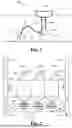


Sources:
- United States Patent and Trademark Office - verify current appl. status at the USPTO↗
Similar patent applications:
Recent applications in this class:
- » 20250341163 2025-11-06
MECHANISMS FOR OPTIMAL OFFSHORE MINERAL MINING - » 20250243757 2025-07-31
MINING VEHICLE FOR COBALT-RICH CRUST FROM THE SEABED - » 20240003253 2024-01-04
WATER BOTTOM RESOURCE COLLECTING METHOD - » 20230332503 2023-10-19
EQUIPMENT AND APPLICATION METHOD FOR SINKAGE DETECTION AND ACTIVE ESCAPE OF DEEP-SEA MINING VEHICLE - » 20230304402 2023-09-28
METHOD AND APPARATUS FOR RETRIEVING DEEP-SEA NODULES - » 20230082082 2023-03-16
Deep-Sea Mining Vehicle - » 20220251955 2022-08-11
Unloading type sinking rescue device of subsea mining vehicle and use method thereof - » 20220243591 2022-08-04
DEEP-SEA ORE HYDRAULIC LIFTING SYSTEM WITH DEEP-SEA SINGLE HIGH-PRESSURE SILO FEEDING DEVICE - » 20200182055 2020-06-11
Submarine shallow hydrate exploitation device and exploitation method thereof - » 20200109628 2020-04-09
Decoupled seafloor mining system
Recent applications for this Assignee:
- » 20260177042 2026-06-25
DOUBLE ACTING PUMP - » 20230415853 2023-12-28
ANCHOR SYSTEMS AND METHODS - » 20220186717 2022-06-16
Pump and associated system and methods - » 20210231113 2021-07-29
Pulsation damping system - » 20170001845 2017-01-05
Fluidically actuatable failsafe disk brake system and lifting device comprising said system - » 20160327032 2016-11-10
HOT SLURRY PUMP - » 20160290045 2016-10-06
Top drive for a drill string - » 20160177946 2016-06-23
Positive displacement pump - » 20160167937 2016-06-16
Lifting-device brake system - » 20150260178 2015-09-17
PISTON MEMBRANE PUMP