Steam Generation Device and Steam Generation Method
US20260185698A1
2026-07-02
18/858,502
2023-04-10
Smart Summary: A steam generation device uses a compressor to suck in and compress steam. It has a special pipe that combines water separated from the steam with the incoming steam. A pressure reducer in this pipe lowers the pressure of the water. Additionally, there is a pre-stage compressor that compresses the steam before it reaches the main compressor. This setup allows for more efficient steam generation by using a two-stage compression process. 🚀 TL;DR
Abstract:
Provided is a steam generation device including a compressor that sucks and compresses steam, a condensate pipe for merging water separated from steam discharged from the compressor with steam sucked into the compressor, and a pressure reducer that is provided in the condensate pipe and depressurizes water flowing in the condensate pipe. Preferably, the steam generation device further includes a pre-stage compressor that compresses steam sucked into the compressor, and has a configuration in which low-pressure steam is compressed by a two-stage compressor.
Inventors:
- Sachio SEKIYA 14 🇯🇵 Tokyo, Japan
- Hiroshi MAITA 7 🇯🇵 Tokyo, Japan
- Hironobu KAWAMURA 3 🇯🇵 Tokyo, Japan
Applicant:
Interested in similar patents?
Get notified when new applications in this technology area are published.
Classification:
F22B37/26 » CPC main
Component parts or details of steam boilers applicable to more than one kind or type of steam boiler Steam-separating arrangements
F22B3/00 » CPC further
Other methods of steam generation; Steam boilers not provided for in other groups of this subclass
F25B30/02 » CPC further
Heat pumps of the compression type
Description
TECHNICAL FIELD
The present invention relates to a steam generation device and a steam generation method.
BACKGROUND ART
PTL 1 discloses a technique for obtaining high-pressure steam by heating a water supply with a heat exchanger using hot water as a heat source to generate low-pressure steam and compressing the low-pressure steam with a compressor. In the technique of PTL 1, some of the high-pressure steam and high-temperature water separated by a gas-liquid separator is merged with the hot water that is the heat source of the heat exchanger to improve the energy efficiency.
CITATION LIST
Patent Literature
-
- PTL 1: JP 2011-64417 A
SUMMARY OF INVENTION
Technical Problem
In a factory or the like, a low-temperature fluid such as steam or hot water that has been used for process heating or the like is generally discharged without being used. Even if such a low-temperature fluid is used, particularly, the low-temperature fluid having a temperature of 100° C. or lower is limited to an application such as hot water supply or room heating, and it is actually difficult to economically recover heat as the temperature becomes lower. If a high-temperature fluid having a temperature higher than 100° C. can be obtained using a low-temperature fluid having a temperature of 100° C. or lower as a heat source, an energy saving measure of reusing exhaust heat which has not been used so far can be proposed.
In the technique of PTL 1, heat recovery is achieved by using some of high-pressure steam and high-temperature water separated by the gas-liquid separator for the heat source of the heat exchanger. However, since the heat exchanger is used for the heat recovery, energy efficiency is restricted by thermal resistance of the heat exchanger.
An object of the present invention is to provide a steam generation device and a steam generation method capable of generating high-pressure steam from exhaust heat of a low-pressure fluid with high efficiency.
Solution to Problem
In order to achieve the above object, the present invention provides a steam generation device including a compressor that sucks and compresses steam, a condensate pipe for merging water separated from steam discharged from the compressor with steam sucked into the compressor, and a pressure reducer that is provided in the condensate pipe and depressurizes water flowing in the condensate pipe.
Advantageous Effects of Invention
According to the present invention, it is possible to generate high-pressure steam from exhaust heat of a low-pressure fluid with high efficiency.
BRIEF DESCRIPTION OF DRAWINGS
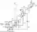
FIG. 1 is a schematic diagram of an example of a steam generation device according to an embodiment of the present invention.
FIG. 2 is a schematic diagram of another example of the steam generation device according to the embodiment of the present invention.
FIG. 3 is a flowchart showing an example of a control procedure of a pressure reducing valve by a computer provided in the steam generation device shown in FIG. 1.
FIG. 4 is a flowchart showing an example of a control procedure of a control valve by the computer provided in the steam generation device shown in FIG. 1.
DESCRIPTION OF EMBODIMENTS
Hereinafter, embodiments of a steam generation device and a steam generation method according to the present invention will be described with reference to the drawings.
(Configuration)
FIGS. 1 and 2 are schematic diagrams of a steam generation device according to an embodiment of the present invention.
In the steam generation device and the steam generation method in the present embodiment, low-temperature water is heated using exhaust heat of a low-temperature fluid such as steam or hot water that has been used for process heating or the like in a factory or the like as a heat source, and low-pressure steam generated by the heating is compressed to generate and supply high-pressure steam to a user.
The steam generation device shown in FIG. 1 includes a low-pressure steam generation device 40A, gas-liquid separators 4 and 5, a low-temperature water circulation pump 10, a low-temperature water supply pump 11, compressors 1 and 2, pressure reducing valves 7 and 8, control valves 12 and 13, a middle-temperature water heat recovery heat exchanger 9, a computer 50, and the like. In the present embodiment, the low-pressure steam generation device 40A includes an exhaust heat recovery heat exchanger 6 and a gas-liquid separator 3. The steam generation device illustrated in FIG. 2 has a configuration in which the low-pressure steam generation device 40A of the steam generation device shown in FIG. 1 is replaced with a low-pressure steam generation device 40B, and has the same configuration as the steam generation device shown in FIG. 1 except for this point.
Hereinafter, each element will be sequentially described.
—Low-Pressure Steam Generation Devices 40A and 40B—
The low-pressure steam generation device 40A (FIG. 1) and the low-pressure steam generation device 40B (FIG. 2) heat water flowing in from the gas-liquid separator 4 through the water feed pipe 20, and generate steam compressed by the compressor 1. The water feed pipe 20 is provided with the pressure reducing valve 7.
The low-pressure steam generation device 40A illustrated in FIG. 1 includes the exhaust heat recovery heat exchanger 6 and the gas-liquid separator 3 as described above.
Low-temperature water is supplied from the gas-liquid separator 3 to the exhaust heat recovery heat exchanger 6 by a pipe 23 and the low-temperature water circulation pump 10. The exhaust heat recovery heat exchanger 6 illustrated in FIG. 1 is a plate heat exchanger, and heats low-temperature water circulating between the exhaust heat recovery heat exchanger 6 and the gas-liquid separator 3 using exhaust heat (for example, about 80° C.) of a low-temperature fluid such as steam or hot water used for process heating or the like in a factory or the like as a heat source. In the exhaust heat recovery heat exchanger 6, some of the heated low-temperature water is vaporized to become low-pressure steam of atmospheric pressure or less. The low-pressure steam is guided to the gas-liquid separator 3 through a pipe 24 together with the low-temperature water.
The gas-liquid separator 3 separates low-temperature water from the low-pressure steam introduced from the exhaust heat recovery heat exchanger 6. During operation of the steam generation device, the inside of the gas-liquid separator 3 is evacuated. Thus, the gas-liquid separator 3 is produced to have a strength that can withstand a state in which the inside has been evacuated. In the gas-liquid separator 3, low-temperature water can be evaporated at atmospheric pressure or less by gas-liquid separation under vacuum. The low-pressure steam obtained by separating the low-temperature water in the gas-liquid separator 3 is guided to the compressor 1 through a pipe 14. Some of the low-temperature water separated from the low-pressure steam in the gas-liquid separator 3 is sent again to the exhaust heat recovery heat exchanger 6 by the low-temperature water circulation pump 10. In addition, some of the low-temperature water inside the gas-liquid separator 3 is sent to the compressors 1 and 2 by the low-temperature water supply pump 11.
Note that, although FIG. 1 illustrates the case where the low-pressure steam generation device 40A is configured to include the exhaust heat recovery heat exchanger 6 that is a plate heat exchanger, the low-pressure steam generation device is not limited to the configuration illustrated in FIG. 1. The configuration illustrated in FIG. 2 is an example in which the low-pressure steam generation device 40B is configured by a falling-liquid film type shell-and-tube type exhaust heat recovery heat exchanger. As an example, the low-pressure steam generation device 40A can be substituted with the low-pressure steam generation device 40B.
The low-pressure steam generation device 40B (shell-and-tube type exhaust heat recovery heat exchanger) includes a tube group 42 configured by a plurality of heat transfer tubes and a low-temperature water spraying device 41. In the low-pressure steam generation device 40B, the low-temperature water inside the body (container) is pumped up by the low-temperature water circulation pump 10, is guided to the low-temperature water spraying device 41 through the pipe 23, is sprayed by the low-temperature water spraying device 41 inside the body, and flows downward on the surface of the heat transfer tube of the tube group 42. The inside of the body of the low-pressure steam generation device 40B may be configured to be in a vacuum state during operation of the steam generation device.
A low-temperature fluid used for process heating or the like in a factory or the like flows through the heat transfer tube of the tube group 42. Low-temperature water flowing downward on the surface of the heat transfer tube is heated by exhaust heat of the low-temperature fluid, and some of the low-temperature water evaporates to generate low-pressure steam. The low-pressure steam generated by the low-pressure steam generation device 40B is guided to the compressor 1 through the pipe 14 as in the example of FIG. 1. Some of the low-temperature water accumulated in the body of the low-pressure steam generation device 40B is supplied to the low-temperature water spraying device 41 as described above, and some is sent to the compressors 1 and 2 by the low-temperature water supply pump 11 as in the example of FIG. 1.
In addition, a water supply pipe 25 is connected to the bodies of the gas-liquid separator 3 and the low-pressure steam generation device 40B. Low-temperature water (for example, tap water) is supplied to the gas-liquid separator 3 and the low-pressure steam generation device 40B through the water supply pipe 25. In the examples of FIGS. 1 and 2, the water supply pipe 25 passes through the middle-temperature water heat recovery heat exchanger 9 using middle-temperature water from the gas-liquid separator 4 flowing in the water feed pipe 20 as a heat source. The supply water flowing in the water supply pipe 25 recovers heat of the middle-temperature water in the middle-temperature water heat recovery heat exchanger 9. However, the middle-temperature water heat recovery heat exchanger 9 can be omitted when unnecessary.
In addition, the gas-liquid separator 3 and the low-pressure steam generation device 40B are provided with a water level sensor 30 that measures a water level of low-temperature water stored in the bodies of the gas-liquid separator 3 and the low-pressure steam generation device 40B. The type of the water level sensor 30 is not limited. The measurement value from the water level sensor 30 is transmitted to the computer 50.
—Compressor 1—
The compressor 1 shown in FIG. 1 is a screw compressor configured to include a male rotor and a female rotor. The compressor 1 sucks, compresses, and pressurizes (for example, about 200 kPa) low-pressure steam (for example, about 50 kPa) generated by the low-pressure steam generation device 40A (low-pressure steam generation device 40B in FIG. 2). In the examples of FIGS. 1 and 2, since the compressors 1 and 2 having a plurality of stages (two stages in the present embodiment) are adopted, the compressor 1 corresponds to a pre-stage compressor that compresses steam sucked into the compressor 2 serving as a post-stage compressor.
Low-temperature water that is separated from low-pressure steam by the gas-liquid separator 3 (the low-temperature steam generation device 40B in the example of FIG. 2) and discharged from the low-temperature water supply pump 11 is supplied to the compressor 1 through a water injection pipe 21. The water injection pipe 21 is provided with a control valve (flow rate regulating valve) 12 that controls a supply amount of low-temperature water to the compressor 1.
The low-temperature water guided through the water injection pipe 21 is ejected into the casing of the compressor 1, seals a gap between the male rotor and the female rotor of the compressor 1, and cools the steam in a compression process so that intermediate-pressure steam obtained by compressing the low-pressure steam in the compressor 1 becomes saturated steam. On the other hand, the low-temperature water heated by cooling the steam in the compression process becomes medium-temperature water (for example, about 120° C.) having a temperature higher than the low-temperature water (for example, about 80° C.) and is discharged from the compressor 1, and at the same time, some of the low-temperature water evaporates in a heating process to become intermediate-pressure steam. The intermediate-pressure steam is discharged from the compressor 1 together with intermediate-pressure steam obtained by compressing low-pressure steam from the low-pressure steam generation device 40A (or 40B), and is guided to the gas-liquid separator 4 through a pipe 15.
—Gas-Liquid Separator 4—
The gas-liquid separator 4 separates the middle-temperature water from the intermediate-pressure steam that is discharged from the compressor 1 and sucked into the compressor 2. The intermediate-pressure steam obtained by separating the middle-temperature water in the gas-liquid separator 4 is guided to the compressor 2 through a pipe 16. The middle-temperature water separated from the intermediate-pressure steam in the gas-liquid separator 4 passes through the water feed pipe 20 and is guided to the gas-liquid separator 3 through the middle-temperature water heat recovery heat exchanger 9 and the pressure reducing valve 7. Since the water feed pipe 20 passes through the middle-temperature water heat recovery heat exchanger 9 and the pressure reducing valve 7, the middle-temperature water is supplied to the gas-liquid separator 3 in a state where the temperature and the pressure of the middle-temperature water are lowered to the same extent as those of the low-temperature water.
In addition, the gas-liquid separator 4 is provided with a water level sensor 31 that measures a water level of middle-temperature water stored in the body of the gas-liquid separator 4. In addition, the gas-liquid separator 4 is provided with a pressure sensor 35 that measures the pressure in the body of the gas-liquid separator 4. Further, the pipe 16 connecting the gas-liquid separator 4 and the compressor 2 is provided with a temperature sensor 33 that measures an outlet steam temperature of the gas-liquid separator 4. The respective measurement values from the water level sensor 31, the pressure sensor 35, and the temperature sensor 33 are transmitted to the computer 50. Methods of the water level sensor 31, the temperature sensor 33, and the pressure sensor 35 are not particularly limited.
—Compressor 2—
The compressor 2 is a screw compressor configured to include a male rotor and a female rotor, as in the compressor 1. The compressor 2 sucks, compresses, and pressurizes (for example, about 600 kPa) intermediate-pressure steam (for example, about 200 kPa) introduced from the gas-liquid separator 4 through the pipe 16.
In addition, middle-temperature water separated from the intermediate-pressure steam by the gas-liquid separator 4 is supplied as low-temperature water to the compressor 2 through the gas-liquid separator 3, the low-temperature water supply pump 11, and a water injection pipe 22. The water injection pipe 22 is provided with a control valve (flow rate regulating valve) 13 that controls a supply amount of low-temperature water to the compressor 2.
The low-temperature water guided through the water injection pipe 22 is ejected into the casing of the compressor 2, seals a gap between the male rotor and the female rotor of the compressor 2, and cools the steam in the compression process so that high-pressure steam obtained by compressing the intermediate-pressure steam in the compressor 2 becomes saturated steam. On the other hand, middle-temperature water heated by cooling the steam in the compression process becomes high-temperature water (for example, 150 to 160° C.) having a temperature higher than the middle-temperature water, and is discharged from the compressor 2, and, at the same time, some of the middle-temperature water evaporates in the heating process to become high-pressure steam. The high-pressure steam is discharged from the compressor 2 together with high-pressure steam obtained by further compressing the intermediate-pressure steam from the compressor 1, and is guided to the gas-liquid separator 5 through a pipe 17.
—Gas-Liquid Separator 5—
The gas-liquid separator 5 separates high-temperature water from high-pressure steam discharged from the compressor 2. The high-pressure steam obtained by separating high-temperature water in the gas-liquid separator 5 is supplied to the user through a pipe 18. The high-temperature water separated from the high-pressure steam in the gas-liquid separator 5 is supplied to the condensate pipe 19, is guided to the gas-liquid separator 4 through the pressure reducing valve 8 provided in the condensate pipe 19, and is merged with the steam sucked into the compressor 2. The high-temperature water flowing in the condensate pipe 19 is depressurized through the pressure reducing valve 8, and some is flash-evaporated, has a temperature level (that is, middle-temperature water) substantially equal to the middle-temperature water, and merges with the middle-temperature water in the gas-liquid separator 4. On the other hand, the steam generated by flash evaporation of the high-temperature water merges with the intermediate-pressure steam inside the gas-liquid separator 4 and is supplied to the compressor 2.
In addition, the gas-liquid separator 5 is provided with a water level sensor 32 that measures a water level of high-temperature water stored in the body of the gas-liquid separator 5. In addition, the gas-liquid separator 5 is provided with a pressure sensor 36 that measures the pressure in the body of the gas-liquid separator 5. Further, a pipe 18 for supplying high-temperature steam from the gas-liquid separator 5 to the user is provided with a temperature sensor 34 that measures an outlet steam temperature of the gas-liquid separator 5. The respective measurement values by the water level sensor 32, the pressure sensor 36, and the temperature sensor 34 are transmitted to the computer 50. Methods of the water level sensor 32, the temperature sensor 34, and the pressure sensor 36 are not particularly limited.
—Computer 50—
The computer 50 is a control device that controls the pressure reducing valves 7 and 8, the control valves 12 and 13, and the like. For example, the computer 50 has functions of controlling the control valve 13 in accordance with the measurement values output from the pressure sensor 36 and the temperature sensor 34, and adjusting the amount of water injected to the compressor 2 to make the compressed steam by the compressor 2 into saturated steam. Similarly, the computer 50 also has functions of controlling the control valve 12 in accordance with the measurement values output from the pressure sensor 35 and the temperature sensor 33, and adjusting the amount of water injected to the compressor 1 to make the compressed steam by the compressor 1 into saturated steam.
In addition, the computer 50 has a function of controlling the pressure reducing valve 8 in accordance with the measurement value output from the water level sensor 32 and maintaining the water level in the body of the gas-liquid separator 5. Similarly, the computer 50 also has a function of controlling the pressure reducing valve 7 in accordance with the measurement value output from the water level sensor 31, and controlling the water level in the body of the gas-liquid separator 4. The computer 50 also has a function of controlling a control valve (not shown) provided in the water supply pipe 25 in accordance with the measurement value output from the water level sensor 30 and controlling the water level in the body of the gas-liquid separator 3.
Water injection amount control for the compressors 1 and 2 and water level control for the gas-liquid separators 3, 4, and 5 will be described with reference to FIGS. 3 and 4, respectively.
(Water Injection Amount Control)
FIG. 3 is a flowchart showing an example of a control procedure of the control valve 13 by the computer 50.
Note that the control procedure of the control valve 12 by the computer 50 is similar to the control procedure of the control valve 13. In the following description of the control procedure of the control valve 13, the description of the control procedure of the control valve 12 is replaced by replacing the compressor 2, the control valve 13, the pressure sensor 36, the temperature sensor 34, and the high temperature with the compressor 1, the control valve 12, the pressure sensor 35, the temperature sensor 33, and the medium temperature, respectively.
The control of FIG. 3 is repeatedly performed at a predetermined cycle time (for example, 1 s cycle) by the computer 50, for example, during the operation of the steam generation device of FIG. 1 or 2.
Step S11
First, the computer 50 inputs current measurement values P and T of the pressure and temperature of high-temperature steam, which are output from the pressure sensor 36 and the temperature sensor 34 (Step S11).
Step S12
Then, the computer 50 calculates the saturation temperature T1 of the high-temperature steam discharged from the compressor 2 based on the measurement value P (that is, the actual pressure of the high-temperature steam) output from the pressure sensor 36 (Step S12).
Steps S13 to S15
The computer 50 compares the measurement value T output from the temperature sensor 34 (that is, the actual temperature of the high-temperature steam) with the saturation temperature T1 (Step S13), and controls the control valve 13 such that the measurement value T becomes the saturation temperature T1 (Steps S14 and S15). Specifically, when the measurement value T is higher than the saturation temperature T1, the computer 50 decreases the measurement value T by increasing the opening degree of the control valve 13 and increasing the flow rate of the low-temperature water supplied to the compressor 1 (Step S14). On the contrary, when the measurement value T is lower than the saturation temperature T1, the computer 50 increases the measurement value T by decreasing the opening degree of the control valve 13 and decreasing the flow rate of the low-temperature water supplied to the compressor 1 (Step S15). After executing the processes of Steps S14 and S15, the computer 50 returns the procedure to Step S11.
(Water Level Control)
FIG. 4 is a flowchart showing an example of a control procedure of the pressure reducing valve 8 by the computer 50. According to the procedure illustrated in FIG. 4, the computer 50 controls the pressure reducing valve 8 such that the measurement value L output from the water level sensor 32 (that is, the actual water level of the gas-liquid separator 5) falls within the set range L1-L2. L1 is a lower limit value of the set range, L2 (>L1) is an upper limit value of the set range, and each is set in advance and stored in a memory of the computer 50.
Note that the control procedure of the pressure reducing valve 7 by the computer 50 is similar to the control procedure of the pressure reducing valve 8. In the following description of the control procedure of the pressure reducing valve 8, the description of the control procedure of the pressure reducing valve 7 is replaced by replacing the pressure reducing valve 8, the gas-liquid separator 5, the water level sensor 32, and the high temperature with the pressure reducing valve 7, the gas-liquid separator 4, the water level sensor 31, and the medium temperature, respectively. In addition, a control procedure of a control valve (not illustrated) provided in the water supply pipe 25 is also similar to the control procedure of the pressure reducing valve 8. In the following description of the control procedure of the pressure reducing valve 8, the description of the control procedure of the control valve (not shown) is replaced by replacing the pressure reducing valve 8, the gas-liquid separator 5, the water level sensor 32, and the high temperature with the control valve (not shown), the gas-liquid separator 3 (or the low-pressure steam generation device 40B), the water level sensor 30, and the low temperature, respectively.
The control of FIG. 4 is performed in parallel with the control of FIG. 3, and is repeatedly performed at a predetermined cycle time (for example, 1 s cycle) by the computer 50 during the operation of the steam generation device of FIG. 1 or 2, for example, as in the control of FIG. 3.
Step S21
First, the computer 50 inputs the current measurement value L of the current water level inside the gas-liquid separator 5, which is output from the water level sensor 32 (Step S21).
Steps S22 and S23
Then, the computer 50 compares the measurement value L output from the water level sensor 32 with the lower limit value L1 of the set range (Step S22). When the measurement value L is lower than the lower limit value L1, the computer 50 increases the measurement value L by decreasing the opening degree of the pressure reducing valve 8 and decreasing the outflow flow rate of the high-temperature water from the gas-liquid separator 5 (Step S23). After executing the process of Step S23, the computer 50 returns the procedure from Step S23 to Step S21. When the measurement value L is equal to or higher than the lower limit value L1, the computer 50 causes the procedure to proceed from Step S22 to Step S24.
Steps S24 and S25
When the procedure proceeds to Step S24, the computer 50 compares the measurement value L output from the water level sensor 32 with the upper limit value L2 of the set range. When the measurement value L is higher than the upper limit value L2, the computer 50 decreases the measurement value L by increasing the opening degree of the pressure reducing valve 8 and increasing the outflow flow rate of the high-temperature water from the gas-liquid separator 5 (Step S25). After executing the process of Step S25, the computer 50 returns the procedure from Step S25 to Step S21. When the measurement value L is equal to or lower than the upper limit value L2, the computer 50 maintains the opening degree of the pressure reducing valve 8 and causes the procedure to proceed from Step S24 to Step S21.
Note that, in the flowchart of FIG. 4, the procedure of Steps S22 and S23 and the procedure of Steps S24 and S25 may be reversed.
(Effects)
(1) As described above, the high-temperature water separated from the high-pressure steam discharged from the compressor 2 flows into the intermediate-pressure steam sucked into the compressor 2 through the pressure reducing valve 8. Comparing the inlet side and the outlet side of the compressor 2, for example, the gas-liquid separators 4 and 5 during the operation of the steam generation device, the gas-liquid separator 5 has a higher internal pressure than the gas-liquid separator 4. That is, the high-temperature water inside the gas-liquid separator 5 has a temperature level higher than the middle-temperature water inside the gas-liquid separator 4. In this case, when the high-temperature water inside the gas-liquid separator 5 flows into the gas-liquid separator 4 through the pressure reducing valve 8, some of the high-temperature water is flash-evaporated, and the high-temperature water passing through the pressure reducing valve 8 is cooled down to become middle-temperature water. Then, the middle-temperature water merges with the middle-temperature water inside the gas-liquid separator 4. On the other hand, the steam generated by flash evaporation of the high-temperature water merges with the intermediate-pressure steam inside the gas-liquid separator 4 and is supplied to the compressor 2.
At this time, when the high-temperature water is flash-evaporated, the ratio (flash steam ratio) of flash steam merging with the intermediate-pressure steam inside the gas-liquid separator 4 to the high-temperature water is calculated by the following (Expression 1).
F = ( h 3 - h 2 ) / r 2 × 100 ( Expression 1 )
-
- F: Flash steam rate (wt %)
- h3: Specific enthalpy (kJ/kg) of high-temperature water
- h2: Specific enthalpy (kJ/kg) of middle-temperature water
- r2: Evaporation latent heat (kJ/kg) of flash steam
For example, when the high-temperature water is set to 150° C., the middle-temperature water is set to 120° C., and the absolute pressure inside the gas-liquid separator 4 is set to 200 kPa, h3=628 kJ/kg, h2=502 kJ/kg, r2=2204 kJ/kg, and the flash steam rate F is 5.7 wt %. That is, in this case, 5.7 wt % of the flow rate of the high-temperature water flowing into the gas-liquid separator 4 from the gas-liquid separator 5 is recovered as the intermediate-pressure steam.
As described above, according to the present embodiment, by depressurizing the high-temperature water separated from steam pressurized by the compressor 2 and returning to the suction side of the compressor 2, the steam generated at the time of depressurizing the high-temperature water can be directly merged with the steam sucked into the compressor 2. That is, the heat quantity other than the heat quantity of the high-pressure steam supplied to the user, that is, the heat quantities of the middle-temperature water and the high-temperature water in the specific examples of FIGS. 1 and 2 can be recovered in the thermal cycle of the steam generation device, and thus it is possible to generate the high-pressure steam with high efficiency with respect to the heat quantity of the heat source. Thus, it is possible to generate the high-pressure steam with high efficiency even from exhaust heat of a low-pressure fluid of 100° C. or lower such as steam or hot water used for process heating in a factory or the like.
Note that the evaporation of the hot water due to the pressure reduction can also occur by the pressure reducing valve 7 similarly to the steam. That is, when the middle-temperature water separated from the intermediate-pressure steam discharged by the compressor 1 is depressurized by the pressure reducing valve 7, steam is generated, and the generated steam merges with the low-pressure steam sucked into the compressor 1. This also provides the same effects as described above.
In addition, in the present embodiment, a configuration in which the high-pressure steam is generated from the low-pressure steam by a plurality of compressors 1 and 2 is made, but a configuration in which the high-pressure steam is generated from the low-pressure steam by a single high-compression-ratio compressor may be considered. For example, when the compressor 1 has a compression ratio at which the pressure of the low-pressure steam can be increased to the pressure level of the high-pressure steam, a configuration in which the compressor 2, the gas-liquid separator 5, and devices and pipes associated therewith are omitted, and the high-pressure steam obtained by separating the high-temperature water by the gas-liquid separator 4 is supplied to the user can be made. Also in this case, flash evaporation can be caused to occur when the high-temperature water flowing into the gas-liquid separator 3 from the gas-liquid separator 4 through the water feed pipe 20 is depressurized by the pressure reducing valve 7, and the flash steam can be merged with the low-pressure steam sucked into the compressor 1.
(2) Since the gas-liquid separator 4 is provided on the suction side of the compressor 2, it is possible to rationally separate the middle-temperature water from the intermediate-pressure steam supplied to the compressor 2. At the same time, since the gas-liquid separator 5 is provided on the discharge side of the compressor 2, it is possible to rationally generate high-temperature water for heat recovery as intermediate-pressure steam. The same applies to the gas-liquid separators 3 and 4 before and after the compressor 1.
However, it is possible to separate water from the steam without using the gas-liquid separators 4 and 5. When it is not necessary to use the gas-liquid separators 4 and 5, it is also possible to adopt a configuration in which at least one of the gas-liquid separators 4 and 5 is omitted or replaced with another element. The same applies to the gas-liquid separators 3 and 4 before and after the compressor 1.
(3) By providing the water injection pipes 21 and 22 for supplying the water separated from the steam by the gas-liquid separators 4 and 5 to the compressors 1 and 2 as seal water for sealing the gap between the male rotor and the female rotor, it is possible to improve the compression efficiency of the compressors 1 and 2 by utilizing the low-temperature water obtained in the system. In addition, by compressing the steam while being cooled by the low-temperature water in the compressors 1 and 2, it is possible to suppress overheated evaporation of the compressed steam. As a result, it is possible to discharge saturated steam from the compressors 1 and 2. In addition, by adding the low-temperature water to the steam in the compression process in the compressors 1 and 2, it is possible to discharge steam containing a large amount of moisture from the compressors 1 and 2. Therefore, it is possible to rationally obtain water in the high-temperature state to be evaporated by the pressure reducing valves 7 and 8 and utilized for heat recovery.
(4) The supply amount of the low-temperature water to the compressors 1 and 2 is controlled such that the temperature of the discharge steam of the compressors 1 and 2, which is measured by the temperature sensors 33 and 34 becomes the saturation temperature calculated based on the measurement values of the pressure sensors 35 and 36. As a result, for example, even if the operating conditions of the steam generation device fluctuate, the supply amount of the low-temperature water to the compressors 1 and 2 is flexibly adjusted to follow the fluctuation of the operating conditions, and the effects of making the discharge steam of the compressors 1 and 2 into the saturated steam can be obtained more rationally.
(5) The water levels of the gas-liquid separators 4 and 5 are controlled within the set range in accordance with the measurement values of the water level sensors 31 and 32. Therefore, the water levels of the gas-liquid separators 4 and 5 are maintained, and it is possible to prevent steam blow-off in the gas-liquid separators 4 and 5.
(6) Since the compressor 1 that compresses the steam sucked into the compressor 2 is provided, and the low-pressure steam is pressurized by the two-stage compressors 1 and 2, it is possible to naturally compress the low-pressure steam to the high-pressure steam at a high compression ratio.
In addition, when the supply flow rate of the high-pressure steam to the user is set to be constant, the compression amount of the low-pressure steam required for the compressor 1 decreases by the merging amount of the steam generated by the flash evaporation of the high-temperature water. Since the shaft power W of the compressor 1 is calculated by the following (Expression 2), it is possible to reduce the shaft power W in proportion to the reduction amount of the low-pressure steam flow D.
W = ( hv 2 - hv 1 ) × D ( Expression 2 )
-
- W: Shaft power (kW)
- hv2: Specific enthalpy (kJ/kg) of discharge steam of compressor 1
- hv1: Specific enthalpy (kJ/kg) of suction steam of compressor 1
- D: Low-pressure steam flow (kg/s)
(7) In addition, in the example of FIG. 1, the low-pressure steam generation device 40A that heats low-temperature water supplied from the gas-liquid separator 4 through the water feed pipe 20 and the pressure reducing valve 7 to generate low-pressure steam compressed by the compressor 1 includes the gas-liquid separator 3 that separates low-pressure steam into gas and liquid under vacuum. Since the inside of the gas-liquid separator 3 is maintained in a vacuum state during the operation of the steam generation device, it is possible to obtain a sufficient amount of low-pressure steam by evaporating low-temperature water at atmospheric pressure or less.
Modified Example
In the examples of FIGS. 1 and 2, the case where the pressure reducing valves 7 and 8 are controlled to control the water levels of the gas-liquid separators 4 and 5 has been exemplified, but the discharge water amounts of the gas-liquid separators 4 and 5 can be adjusted by other types of control valves such as a flow rate regulating valve even without the pressure reducing valves 7 and 8. Therefore, a configuration in which instead of or in addition to the pressure reducing valves 7 and 8, another type of control valve such as a flow rate regulating valve may be provided in the water feed pipe 20 and the condensate pipe 19, and the control valve is controlled by the computer 50 can be adopted.
In addition, in FIGS. 1 and 2, the example in which the pressure reducing valves 7 and 8 are adopted as pressure reducers that depressurize the water feed pipe 20 and the condensate pipe 19 has been described, but the pressure reducers are not limited to the pressure reducing valves 7 and 8 as long as desired pressure reducing effects can be obtained. For example, other configurations capable of obtaining a pressure reducing effect, such as a flow rate regulating valve and a return flow path, can be adopted instead of the pressure reducing valves 7 and 8.
REFERENCE SIGNS LIST
-
- 1 compressor (compressor, pre-stage compressor)
- 2 compressor
- 3 gas-liquid separator (first gas-liquid separator)
- 4 gas-liquid separator (first gas-liquid separator, second gas-liquid separator)
- 5 gas-liquid separator (second gas-liquid separator)
- 6 exhaust heat recovery heat exchanger
- 7 pressure reducing valve (control valve)
- 8 pressure reducing valve
- 12, 13 control valve
- 19 condensate pipe
- 20 water feed pipe (condensate pipe)
- 21, 22 water injection pipe
- 30, 31, 32 water level sensor
- 33, 34 temperature sensor
- 35, 36 pressure sensor
- 40A, 40B low-pressure steam generation device
- 50 computer
- L measurement value (water level)
- L1 lower limit water level (set range)
- L2 upper limit water level (set range)
- P measurement value (pressure)
- T measurement value (temperature)
- T1 saturation temperature
Claims
1. A steam generation device, comprising:
a compressor that sucks and compresses steam;
a condensate pipe for merging water separated from steam discharged from the compressor with steam sucked into the compressor; and
a pressure reducer that is provided in the condensate pipe and depressurizes water flowing in the condensate pipe.
2. The steam generation device according to claim 1, further comprising:
a first gas-liquid separator that separates water from the steam sucked into the compressor; and
a second gas-liquid separator that separates water from the steam discharged from the compressor and supplies the separated water to the condensate pipe.
3. The steam generation device according to claim 2, further comprising:
a water injection pipe for supplying the water separated from the steam by the first gas-liquid separator to the compressor.
4. The steam generation device according to claim 3, further comprising:
a pressure sensor that measures a pressure of the second gas-liquid separator;
a temperature sensor that measures an outlet steam temperature of the second gas-liquid separator;
a control valve provided in the water injection pipe; and
a computer that controls the control valve in accordance with measurement values output from the pressure sensor and the temperature sensor,
wherein the computer
calculates a saturation temperature of the steam discharged from the compressor based on the measurement value output from the pressure sensor,
compares the measurement value output from the temperature sensor with the saturation temperature, and
controls the control valve such that the measurement value output from the temperature sensor reaches the saturation temperature.
5. The steam generation device according to claim 3, further comprising:
a water level sensor that measures a water level of the second gas-liquid separator;
a control valve provided in the condensate pipe; and
a computer that controls the control valve in accordance with a measurement value output from the water level sensor,
wherein the computer controls the control valve such that the measurement value output from the water level sensor falls within a set range.
6. The steam generation device according to claim 3, further comprising:
a water level sensor that measures a water level of the first gas-liquid separator;
a water feed pipe that feeds water from the first gas-liquid separator;
a control valve provided in the water supply pipe; and
a computer that controls the control valve in accordance with a measurement value output from the water level sensor,
wherein the computer controls the control valve such that the measurement value output from the water level sensor falls within a set range.
7. The steam generation device according to claim 1, further comprising
a pre-stage compressor that compresses the steam sucked into the compressor.
8. The steam generation device according to claim 2, further comprising
a pre-stage compressor that compresses the steam sucked into the compressor and supplies the compressed steam to the first gas-liquid separator.
9. The steam generation device according to claim 8, further comprising:
a water feed pipe that feeds water from the first gas-liquid separator; and
a low-pressure steam generation device that heats water supplied from the first gas-liquid separator through the water feed pipe and generates steam compressed by the pre-stage compressor.
10. The steam generation device according to claim 9, wherein the low-pressure steam generation device includes a third gas-liquid separator that performs gas-liquid separation under vacuum.
11. A steam generation method comprising:
depressurizing water separated from steam discharged from a compressor to cause flash evaporation; and
merging steam generated by the flash evaporation with steam sucked into the compressor.
Images & Drawings included:


Sources:
- United States Patent and Trademark Office - verify current appl. status at the USPTO↗
Similar patent applications:
- » 20100083845
STEAM GENERATOR COOKING DEVICE METHOD FOR OPERATING AND PRODUCING A STEAM GENERATOR AND METHOD FOR COOLING A HEATING DEVICE - » 20060200325
Generated steam estimation method and device for heat recovery steam generator, and maintenance planning support method and system for power generation facility - » 20060101588
Washing machine with steam generating device and method for controlling the same - » 20250027258
CLOTHING TREATMENT APPARATUS PROVIDED WITH STEAM GENERATION DEVICE, AND METHOD FOR CONTROLLING CLOTHING TREATMENT APPARATUS - » 20070227145
Method and Device for Generating Steam Suited to Oxycombustion - » 20180003377
Method and device for generating steam comprising a scale container and steamer appliance with such a device - » 20180142883
Device and method for generating steam - » 20120012280
DEVICE AND METHOD FOR GENERATING STEAM WITH A HIGH LEVEL OF EFFICIENCY - » 20120210997
METHOD AND DEVICE FOR GENERATING STEAM AND LOW OXYGEN GAS - » 20150343107
Method and device for generating steam and gaseous hydrogen peroxide
Recent applications in this class:
- » 20210239314 2021-08-05
Systems and methods for removing organic compounds from steam - » 20190003701 2019-01-03
Fluid utilization facility management method and fluid utilization facility management system - » 20170153023 2017-06-01
Fluid utilization facility management method and fluid utilization facility management system - » 20150241055 2015-08-27
NUCLEAR POWER PLANT AND NON-CONDENSABLE GAS EXTRACTION METHOD THEREFOR - » 20120227405 2012-09-13
Cyclone separator for the phase separation of a multiphase fluid stream, steam turbine system having a cyclone separator and associated operating method - » 20120117928 2012-05-17
Multi-stage steam-water separation device and steam-water separator - » 20120031351 2012-02-09
Steam water separator, use of such water steam separator, and method for separating steam and water - » 20110162592 2011-07-07
CONTINUOUS STEAM GENERATOR