DEMISTER EVAPORATOR DISPLACEMENT ARRAY
US20260185751A1
2026-07-02
19/433,392
2025-12-26
Smart Summary: An evaporator is designed for heating and cooling systems. It has a shell with tubes that carry a fluid inside. Inside this shell, there is a special arrangement called a displacement array, which includes baffles and demisters. These parts work together to separate gas from any liquid that might be mixed in. The process involves heating the fluid, turning it into gas, and then using the demisters to clean out any leftover liquid. 🚀 TL;DR
Abstract:
An evaporator is for a heating, ventilation, air conditioning, and refrigeration (HVACR) system and includes a shell with an internal space, tubes for a process fluid extending through the internal space, and a displacement array disposed in the internal space. The displacement array includes baffles, demisters, and channels that extend through the displacement array. Each channel includes a demister portion and a baffle portion configured to discharge gaseous working fluid into the demister portion shaped to remove entrained liquid working fluid. A method for operating an evaporator includes directing working fluid into an internal space of a shell, and heating, with working fluid flowing though tubes, the working fluid within channels of a displacement array to generate gaseous working fluid. The method further includes directing gaseous working fluid from a baffle portion through a demister portion in each channel to remove entrained liquid working fluid.
Applicant:
Interested in similar patents?
Get notified when new applications in this technology area are published.
Classification:
F25B39/028 » CPC main
Evaporators; Condensers; Evaporators having distributing means
F25B43/00 » CPC further
Arrangements for separating or purifying gases or liquids ; Arrangements for vaporising the residuum of liquid refrigerant, e.g. by heat
F25B2339/02 » CPC further
Details of evaporators; Details of condensers Details of evaporators
F25B2339/0242 » CPC further
Details of evaporators; Details of condensers; Details of evaporators; Evaporators with refrigerant in a vessel in which is situated a heat exchanger having tubular elements
F25B2400/23 » CPC further
General features or devices for refrigeration machines, plants or systems, combined heating and refrigeration systems or heat-pump systems, i.e. not limited to a particular subgroup of Separators
F25B39/02 IPC
Evaporators; Condensers Evaporators
Description
FIELD
This disclosure relates to heating, ventilation, air-conditioning, and refrigeration (“HVACR”) systems. More particularly, this disclosure relates to evaporators used in HVACR systems.
BACKGROUND
HVACR systems are generally used to heat, cool, and/or ventilate an enclosed space (e.g., an interior space of a commercial building or a residential building, an interior space of a refrigerated transport unit, or the like). A HVACR system may include a refrigerant circuit that utilizes a working fluid for providing cooled or heated air to an area. Evaporators can have different configurations for heating the working fluid with a process fluid (e.g., air, chiller liquid, intermediate liquid, water, and the like). Flooded and falling-film evaporators can employ a tube bundle within a shell. Such evaporators are typically used in chiller type HVACR systems to cool the process fluid (e.g., water, chiller liquid, and the like), and the cooled process fluid is used to cool air (e.g., in an air-handling unit or the like) which is then supplied to conditioned enclosed space. Due to the spacing within the volume of the shell, such as between the tubes of the tube bundle, through which the process fluid flows, a relatively large quantity of liquid working fluid may be needed to ensure wetting of the entire outer surfaces of the tubes and achieve a maximized efficiency of the evaporator.
SUMMARY
In an embodiment an evaporator for a heating, ventilation, air conditioning, and refrigeration (HVACR) system includes a shell with an internal space, tubes extending through the internal space, and a displacement array disposed in a bottom portion of the internal space. The tubes are configured to pass process fluid through the shell to heat working fluid within the internal space. The displacement array includes baffles, demisters disposed over the baffles in a vertical direction, channels extending through the displacement array. The tubes extend through the baffles of the displacement array. Each channel includes a baffle portion defined by the baffles and a demister portion defined by the demisters. The baffle portion is configured to discharge gaseous working fluid into the demister portion. The demister portion has a shape configured to remove entrained liquid working fluid from the gaseous working fluid.
In an embodiment, the baffles are configured to discharge the gaseous working fluid from the baffle portion of each of the channels at a respective baffle discharge entrainment (BDE) velocity for the baffle portion.
In an embodiment, for each of the channels, the respective BDE velocity corresponds to, in a direct path from an end orifice of the baffle portion to a suction zone, a velocity that causes discharging of entrained liquid working fluid into the suction zone of the shell.
In an embodiment, the direct path from the end orifice of the baffle portion to the suction zone is blocked by the demisters.
In an embodiment, the direct path extends in the vertical direction.
In an embodiment, for each of the channels, the channel has a respective width configured to cause the velocity of the gaseous working fluid discharged from the baffle portion to be greater than at BDE velocity.
In an embodiment, the shape of the baffle portion of each of the channels is a tortuous shape.
In an embodiment, in each of the channels, an end orifice of the baffle portion is covered in a vertical direction by a respective one of the demisters.
In an embodiment, the displacement array includes a plurality of displacers that are stacked in a lateral direction different from the vertical direction. Each of the displacers includes a respective one of the baffles and a respective one of the demisters, and each of the channels extends between a respective pair of the displacers.
In an embodiment, the demisters each extend in the vertical direction and in the lateral direction such that the demister in each one of the displacers covers in a vertical direction an end orifice of the baffle portion formed by said one of the displacers and an adjacent one of the displacers.
In an embodiment, a method is directed to operating an evaporator in an HVACR system. The method includes directing working fluid into an internal space of a shell. A displacement array is disposed in the internal space of the shell and tubes extending through the internal space and through the displacement array. The displacement array includes baffles and demisters disposed over the baffles in a vertical direction. The method also includes heating the working fluid within channels of the displacement array to generate gaseous working fluid from the working fluid by passing a process fluid through the tubes. Each of the channels includes a baffle portion defined by the baffles and a demister portion defined by the demisters. The method further includes discharging the gaseous working fluid from the shell which includes directing the gaseous working fluid from the baffle portion to the demister portion in each channel. The discharging of the gaseous working fluid also includes directing the gaseous working fluid through the demister portion in each channel to remove entrained liquid working fluid of the working fluid from the gaseous working fluid.
In an embodiment, directing the gaseous working fluid through the demister portion in each channel includes directing the gaseous working fluid through a tortuous path of the demisters portion in each channel.
In an embodiment, each of the channels is defined by respective pair of the baffles and a respective pair of the demisters.
In an embodiment, the directing of the gaseous working fluid from the baffle portion to the demister portion in each channel includes directing the gaseous working fluid from an end orifice of the baffle portion in each channel at a respective baffle discharge entrainment (BDE) velocity.
In an embodiment, for each of the channels, the respective BDE velocity corresponds to, in a direct path from an end orifice of the baffle portion to a suction zone, a velocity that causes discharging of entrained liquid working fluid into the suction zone of the shell.
In an embodiment, the heating of the working fluid within channels of the displacement array by passing a process fluid through the tubes includes passing the working fluid along an outer surface of the tubes.
In an embodiment, the discharging of the gaseous working fluid from the shell includes directing the gaseous working fluid from the displacement array to and through an outlet in the shell. The gaseous working fluid discharged through the outlet is substantially free of the liquid working fluid.
DRAWINGS
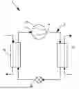
FIG. 1 shows a schematic diagram of an embodiment of a refrigerant circuit in a heating, ventilation, air conditioning, and refrigeration (HVACR) system.
FIG. 2 shows an end view of an embodiment of an evaporator.
FIG. 3 shows a front perspective view of a displacement array of the evaporator in FIG. 2, according to an embodiment.
FIG. 4 shows a front perspective view of a displacer of the displacement array in FIG. 3, according to an embodiment.
FIG. 5 shows a schematic side view of the displacement array in the evaporator of FIG. 2, according to an embodiment.
FIG. 6 shows a front perspective view of another embodiment of a displacement array for an evaporator, according to an embodiment.
FIG. 7 a block flow diagram of an embodiment of a method of operating an evaporator in a HVACR system.
Like numbers represent like features.
DETAILED DESCRIPTION
A heating, ventilation, air conditioning, and refrigeration (“HVACR”) system is generally configured to heat and/or cool an enclosed space (e.g., an interior space of a commercial or residential building, an interior space of a refrigerated transport unit, or the like). The HVACR system includes a heat transfer circuit that includes a compressor and a working fluid (e.g., a refrigerant, a refrigerant mixture, or the like) that circulates through the heat transfer circuit. The working fluid is utilized to heat or cool a process fluid (e.g., air, water and/or glycol, or the like).
The HVACR system includes an evaporator exchanges heat between the working fluid and the process fluid to cool the process fluid, which heats and evaporates (e.g., vaporizes the working fluid). In shell-and-tube types of evaporators, the process fluid can flow inside tubes within the shell and the working fluid is external to the tubes within the shell. Baffling, spacers, etc. can be employed to reduce the amount of working fluid (i.e., the charge of working fluid) needed to ensure adequate wetting within the shell (e.g., adequate wetting of the outsides of the tubes). High velocities of working fluid within the shell of the evaporator can cause entrainment of liquid working fluid in the gaseous working fluid discharged from the evaporator (i.e., can cause liquid carryover from the evaporator to the compressor). Baffles provided within the shell are generally spaced apart to avoid these higher gas velocities that cause liquid carryover from the evaporator.
Embodiments disclosed herein are directed to evaporators, the HVACR systems that include evaporators, and methods of operating evaporators that utilize displacement arrays that create high velocity flows while maintaining little to no discharge of entrained liquid from the evaporator. The higher velocity flows can increase the efficiency of the evaporator by increasing mixing at surfaces of the tubes.
FIG. 1 is a schematic diagram of an embodiment of a refrigerant circuit 5 in an HVACR system 1. In an embodiment, the heat transfer circuit 5 is utilized in a HVACR system. The refrigerant circuit 5 includes a compressor 10, a condenser 20, an expansion device 30, and an evaporator 40. In an embodiment, the refrigerant circuit 5 can be modified to include additional components, such as, for example, an economizer heat exchanger, one or more valve(s), sensor(s) (e.g., a flow sensor, a temperature sensor, and the like), a receiver tank, and the like. Dotted lines are provided in FIG. 1 to indicate fluid flows through some components (e.g., condenser 20, evaporator 40) for clarity, and should be understood as not specifying a specific route in each component.
The components of the refrigerant circuit 5 are fluidly connected. The refrigerant circuit 5 can be configured as a cooling system that can be operated in a cooling mode (e.g., a fluid chiller of an HVACR system, an air conditioning system, or the like), or the refrigerant circuit 5 may be configured as a heat pump system that can be run in a cooling mode or a heating mode.
A working fluid flows through the refrigerant circuit 5. The working fluid in the refrigerant circuit 5 flows through the compressor 10, the condenser 20, the expansion device 30, the evaporator 40, and back to the compressor 10. The working fluid can include one or more refrigerant(s).
Working fluid in a lower pressure gaseous state or mostly gaseous state is drawn into the suction inlet 12 of the compressor 10. The working fluid is compressed as it flows through the compressor 10 from the suction inlet 12 to the discharge outlet 14 of the compressor 10. The working fluid flows from the discharge outlet 14 of the compressor 10 to the condenser 20.
A first process fluid PF1 flows through the condenser 20 separate from the working fluid. The condenser 20 is a heat exchanger that allows the working fluid and the first process fluid PF1 to be in a heat transfer relationship without physically mixing as they each flow through the condenser 20. As the working fluid flows through the condenser 20, the working fluid is cooled by the first process fluid PF1. Accordingly, the first process fluid PF1 is heated by the working fluid and exits the condenser 20 at a higher temperature relative to temperature at which it entered the condenser 20. In an embodiment, the first process fluid PF1 may be air, water and/or glycol, or the like that is suitable for absorbing and transferring heat from the working fluid and the refrigerant circuit 5. For example, the first process fluid PF1 may be ambient air circulated from an outside atmosphere, water to be heated as hot water, or any suitable fluid for transferring heat from the refrigerant circuit 5. The working fluid is cooled by the condenser 20 and becomes liquid or mostly liquid as it is cooled in the condenser 20.
The liquid/gaseous working fluid flows from the condenser 20 to the expansion device 30. The expansion device 30 allows the working fluid to expand. The expansion causes the working fluid to significantly decrease in temperature. An “expansion device” as described herein may also be referred to as an expander. In an embodiment, the expander may be an expansion valve, expansion plate, expansion vessel, orifice, or the like, or other such types of expansion mechanisms. It should be appreciated that the expander may be any type of expander used in the field for expanding a working fluid to cause the working fluid to decrease in temperature. The gaseous/liquid working fluid has a lower temperature after being expanded by the expansion device 30.
The lower temperature gaseous/liquid working fluid then flows from the expansion device 30 to and through the evaporator 40. A second process fluid PF2 also flows through the evaporator 40 separately from the working fluid. The evaporator 40 is a heat exchanger that allows the working fluid and the second process fluid PF2 to be in a heat transfer relationship within the evaporator 40 without physically mixing. As the working fluid and the second process fluid PF2flow through the evaporator 40, the working fluid absorbs heat from the second process fluid PF2 which cools the second process fluid PF2. Accordingly, the second process fluid PF2 exits the evaporator 40 at a lower temperature than the temperature at which it entered the evaporator 40. The working fluid is gaseous or mostly gaseous as it exits the evaporator 40. The working fluid flows from the evaporator 40 to the suction inlet 12 of the compressor 10.
In an embodiment, the second process fluid PF2 is air cooled by the HVACR system and ventilated to the enclosed space to be conditioned. In an embodiment, the second process fluid PF2 is an intermediate fluid (e.g., water, heat transfer fluid, or the like), and the cooled second process fluid PF2 may be utilized by the HVACR system to cool air in or ventilated to the enclosed space to be conditioned.
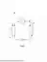
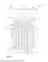
FIG. 2 shows an end view of an embodiment of an evaporator 100. For example, the evaporator 100 in FIG. 2 may be employed as the evaporator 40 in the refrigerant circuit 5 of the HVACR system 1 of FIG. 1. The evaporator 100 in FIG. 1 is a tube-and-shell type heat exchanger. The evaporator 100 in FIG. 1 is an example of a flooded evaporator.
The evaporator 100 includes a shell 110 and tubes 122 disposed within the shell 110. A process fluid (e.g., second process fluid PF2 in FIG. 1, chiller fluid, water, or the like) flows through the tubes 122. The shell 110 includes an internal space 112 through which the process fluid flows. The tubes 122 extend through the internal space 112 of the shell 110. Working fluid is external of the tubes 122 within the shell 110 and contacts the outsides 124 of the tubes 122. The process fluid (via heat transfer) heats and vaporizes the working fluid contacting the exterior of the tubes 122. Within the shell 110, the working fluid is present in two phases of a gaseous portion and liquid portion. The shell 110 includes an inlet 114 and an outlet 116. Working fluid enters the shell 110 via the inlet 114 and exits the shell 110 via the outlet 116. The working fluid can enter the evaporator 100 through a lower portion of the shell (e.g., through the bottom of the shell). Within the evaporator 100, the liquid portion of working fluid contacts the tubes 122 and is vaporized. The gaseous working fluid is discharged from the shell 110 via the outlet 116.
The evaporator 100 includes a displacement array 130 disposed within the shell 100. The tubes 122 extend through the displacement array 130. For example, the tubes 122 extend through corresponding opening 142 in the displacement array 130. The displacement array 130 can also support the tubes 122 within the shell 100 (e.g., vertically support the tubes 122). The liquid working fluid contacts the tubes 122 within the displacement array 130. A majority of the liquid working fluid is heated and then vaporized within the displacement array by the process fluid flowing through the tubes 122. The gaseous and liquid working fluid is discharged from a top of the displacement array 130. The gaseous working fluid flows out of the shell 110 through the outlet 116. Any remaining liquid working fluid is configured to fall back onto the tubes 122 and/or flow back to the bottom of the shell 110. The flow of the working fluid through the displacement array 130 is discussed in more detail below.
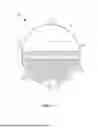
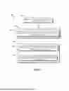
FIG. 3 shows a front perspective view of the displacement array 130, according to an embodiment. FIG. 4 shows a front perspective view of one displacer 132 of the displacement array 130, according to an embodiment. The displacement array 130 is formed of a plurality of the displacers 132. As shown, the plurality of the displacers 132 are in a stacked configuration (e.g., stacked in direction D2) to form the displacement array 130. As shown in FIG. 4, each displacer 132 can have a generally planar shape. The displacement array includes baffles 140 and demisters 160. Each of the displacers 132 includes a respective baffle 140 and a respective demister 160.
The demisters 160 are disposed over the baffles 140 (e.g., disposed on the baffles 140). In an embodiment, the demisters 160 may be a separate component from the baffle 140. In another embodiment, the demisters 160 and the baffles may be formed as a single component (e.g., each displacer 132 being a single component that includes a baffle 140 and a demister 160). The tubes 122 extend through the baffles 140 of the displacement array 130 (e.g., see FIG. 2). As shown in FIGS. 3 – 4, the baffles 140 can includes openings 142 corresponding to the tubes 122. The baffles 140 can support the tubes 122 within the shell 110 of the evaporator 100 (e.g., see FIG. 2). The evaporator 110 includes a suction zone SZ within the shell 110. The suction zone 110 is an upper portion of the internal space 112 of the shell 110. The suction zone SZ is discussed in more detail below.
The displacement array 130 includes channels 134 that extend through the displacement array 130. The channels 134 are configured to direct working fluid through the displacement array 130 across the tubes 122. The channels 134 are formed between the displacers 132 (e.g., each channel 134 formed between an adjacent pair of the displacers 132). The channels 134 direct the working fluid upward through the displacement array 130. The working fluid flowing through the channels 134 flows across (e.g., into contact with) the outer surfaces of the tubes 122.
The displacement array 130 includes spacers 144 that space apart surfaces 146 of adjacent baffles 130. This spacing forms the channels 134 (e.g., the surfaces 146 defining the front and rear of the channels 134) between the displacers 132. In particular, this spacing forms the channel 143 between each adjacent pair of baffles 132. For example, in the illustrated embodiment, each baffle 140 includes a spacer 144 that prevents contact of a front surface 146 from a rear surface (obscured in FIGS. 3 – 4) of the adjacent baffle 140 in the displacement array 130. It should be appreciated that the spacers 144 in another embodiment may be provided in a different structure in other embodiments. For example, the displacement array 130 in an embodiment may have the spacers 144 provided on a rear surface of the baffles 144. For example, the displacement array 130 in an embodiment may have the spacers 144 provided as a separate component from the baffles 140.
The channels 134 have inlets 136 and outlets 138. Each channel 134 can have a respective inlet 136 and a respective outlet 138. The inlets 136 are disposed at the bottom of the displacement array 130 (e.g., at the bottoms of the baffles 140). For example, the inlets 136 are formed by the baffles 140 (e.g., each inlet 136 formed by an adjacent pair of the baffles 140). The outlets 138 are disposed at the top of the displacement array 130 (e.g., at the tops of the demisters 160). For example, the outlets 138 are formed by the demisters 160 (e.g., each outlet 138 formed by an adjacent pair of the baffles 140). Liquid working fluid enters the channels 134 via the inlets 136, is vaporized in the channels 134 as the liquid working fluid flows across the tubes 122, and the gaseous working fluid is discharged from the outlets 138 of the channels 134.
FIG. 5 is schematic side view of the displacement array 130 in the evaporator 100, according to an embodiment. The displacement array 130 is disposed within the shell 110 and the tubes 122 extend through the displacement array 130. The displacers 132 are simplified for illustrated purposes in FIG. 5. For example, spacers in the displacement array 130 are not illustrated in FIG. 5. The number of displacers 132 in the displacement array 130 and the number of tubes 122 are reduced for clarity.
Liquid working fluid enters the shell 110 via the inlet 114 and gaseous working fluid exits the shell 110 via the outlet. The liquid working fluid pools at the bottom of the shell 110. For example, the baffles 140 of the displacement array 130 are configured to be disposed in the pooled liquid working fluid in the shell 110. A majority of the tubes 122 are disposed in the pooled liquid working fluid.
Each channel 134 includes a baffle portion 135A and a demister portion 135B. The baffle portion 135A of the channel 134 is defined by the baffles 140 (e.g., defined by an adjacent pair of baffles, portion that extends between an adjacent pair of baffles 140). The demister portion 135B of the channel 135A is defined by the demisters 160 (e.g., defined by an adjacent pair of demisters, portion that extends between an adjacent pair of demisters). The baffle portion 135A is an inlet portion of the channel 134 that extends from the inlet 136 of the channel 134. The demister portion 135B is an outlet portion of the channel 134 that extends to the outlet 138 of the channel 134. Each channel 134 may also include an end orifice 148 that is the orifice formed at the end of the channel portion 135A (e.g., the outlet of the channel portion 135A). For example, working fluid is discharged from between the baffles 140 to between the demisters 160 via the end orifice 148. The end orifice 148 being formed at the end of the channel portion 135A closest to the demisters (e.g., at the end closest to the demister portion 135B, at the end that connects to the demister portion 135B).
The channels 134 each have a width WC. The width Wc extends in the thickness direction of the displacement array 130 (e.g., lateral direction D3). The tubes also extend through the displacement array in the thickness direction of the displacement array 130. For example, a width WC of the channels 134 can be changed by selecting a width of the spacers 144. In the illustrated embodiment, the spacers 144 on the baffles 130 may have a larger/smaller width such that the width WC of the channels 134 is larger/smaller.
In the channels 134, liquid working fluid flows across the outer surfaces of the tubes 122 is heated and vaporized to generate gaseous working fluid. The gaseous working fluid then rises and flows out of the channels 134. The phase change causes expansion of the working fluid within the channels 134 and results in an increased velocity of gaseous working upwards in the channels 134. Gaseous working fluid generated at the lower tubes 122 flows causing flow of liquid/gas working fluid across the higher tubes 122. The large volume of the gaseous working fluid relative to liquid working fluid also results in the gaseous working fluid increases the upward velocity of working fluid in the channel 134.
In the illustrated embodiment, the baffle portion 135A of the channel 134 includes the tubes 122, such that the heating and vaporization of the working fluid occurs in the baffle portion 135A. The working fluid flows from the baffle portion 135A to the demister portion 135B at velocity V1. This velocity V1 may also be referred to as an intermediate discharge velocity of the channel 134. The intermediate discharge velocity V1 is the velocity of the gas discharged from the baffle portion 135A (e.g., velocity of the discharged from the baffle portion 135A into the demister portion 135B). For example, the intermediate discharge velocity V1 would be the velocity of the working fluid discharged if the demisters 160 were not present. The width Wc of the channel 134 can be selected so as to provide the desired intermediate discharge velocity V1 of the channel 134.
The shell 110 contains the suction zone SZ. The suction zone SZ extends from the outlet 116 of the shell 110. The suction zone SZ is an upper portion of the internal space 112 of the shell 110 (e.g., is an upper portion of the open volume of the internal space 112). As shown in FIG. 5, the suction zone SZ is disposed above the displacement array 130. The suction zone SZ defines the portion of the internal space 112 in which the gaseous working fluid is suctioned out of the shell 110 through the outlet 114. Any gaseous working fluid containing entrained liquid working fluid in suction zone SZ is suctioned/discharged from the evaporator 100 through the outlet 116. This suction of liquid working fluid through the outlet 11 can generally be referred to as liquid carryover.
When the demisters 160 are not present (e.g., if the demisters 160 were omitted), a direct path (e.g., straight path) is formed from the end of each channel 134 (e.g., from the end orifice 148) to the suction zone 138. In a configuration when the demisters 160 are not present, the working fluid would be discharged from the end orifice 148 in a direct path to the suction zone SZ. A velocity of working fluid flowing in a direct path from the end orifice 148 to the suction zone SZ that direct liquid working fluid into the suction zone SZ can be referred to as a baffle discharge entrainment (“BDE”) velocity. For example, without the demisters, the working fluid having a velocity at the end orifice 148 that is a BDE velocity would result in (entrained) liquid working fluid being discharged into the suction zone SZ causing liquid carryover. “BDE velocity” refers to any velocity in a range that causes working fluid flowing in a direct path from a particular end orifice 148 to the suction zone SZ to direct liquid working fluid (e.g., liquid working fluid entrained in gaseous working fluid) into the suction zone SZ (e.g., any velocity that is at or above the minimum velocity in the direct path from a particular end orifice 148 to the suction zone SZ to direct liquid working fluid (e.g., liquid working fluid entrained in gaseous working fluid) into the suction zone SZ). For example, in previous configurations that do not include the demisters, baffles were configured to have the velocity of working fluid discharged from the baffles to be less than the BDE velocity. The manner of determining the BDE velocity is not particularly limited. For example, BDE velocity may be determined based on testing for a comparable displacement array that does not include the demisters 130. For example, the BDE velocity may be determined using computational modeling for the evaporator 130 (and/or the displacement array 130. The channels 134 are configured to have an end orifice velocity V1 that is a BDE velocity.
As shown in FIG. 5, each demister 160 extends upwards (e.g., in vertical direction V1) and over the adjacent baffle portion 135A of the channel 134 defined by the respective demister 160. The demisters 160 are configured to overlap the channels 134 in a height direction of the displacement array 130 (e.g., in the vertical direction D1). Each demister 160 is configured to cover the end orifice 148 of an adjacent channel 134 in the height direction. Each demister 160 extends in the thickness direction of the displacement array 130 (e.g., in the lateral direction D2 perpendicular to the vertical direction D1) to the adjacent baffle 140 (e.g., the baffle 140 of the adjacent displacer 132). The demister 160 extends to overlap in the height direction with the adjacent baffle 140. The demisters 160 prevent a direct path from the end orifice 148 of each channel 134 to the suction zone SZ.
The working fluid flowing in the channel 134 from the baffle portion 135A (e.g., to the demister portion 135B, at the end orifice 148) contains gaseous working fluid and liquid working fluid. The liquid working fluid is entrained in the gaseous working fluid. The demister portion 135B is configured to remove the entrained liquid working fluid from the gaseous working fluid. The demister portion 135B is a tortious path configured to separate entrained liquid working fluid from the gaseous working fluid. For example, the liquid droplets of working fluid in the gaseous working fluid impact the demisters 160 as the gaseous working fluid flows through the demister portion 135B of the channels 134. The displacement array 130 is configured such that the gaseous working fluid discharged from the outlets 138 of the displacement array 130 is substantially free of entrained liquid working fluid. The gaseous working fluid then flows within the shell 110 from the displacement array 130 to the outlet 116 of the shell 110.
The flow of the working fluid between the demisters 160 (e.g., through the demister portion 135B of the channels 134) removes entrained liquid from the gaseous working fluid. The demisters 160 are configured to prevent the relatively high intermediate discharge velocity V1 (i.e., at or greater than the BDE velocity) from causing discharge of entrained liquid into the suction zone SZ and liquid carryover. The relatively higher velocity through the baffle portion 135A of the channels 134 increases the flow across the outer surface of the tubes 122, which advantageously increases heat transfer to the working fluid at the tubes 122 (e.g., increases heat transfer from the outer surface of the tubes to the working fluid).
FIG. 6 is a front perspective view of another embodiment of displacement array 230 for an evaporator. The displacement array 230 is configured to be disposed in lower portion of a shell of an evaporator with the tubes (for process fluid) extending through the displacement array 230. For example, the displacement array 230 is configured to be disposed inside a shell of the evaporator in a similar manner as discussed for the displacement array 130 in FIGS. 2 – 5.
The displacement array 230 includes a plurality of displacers 232. The displacement array includes baffles 240 and demisters 260. Each of the displacers 232 includes a respective baffle 240 and a respective demister 260. The baffles 240 and the demisters 260 in the displacement array 230 can have a similar configuration to the baffles 140 and the demisters 160, respectively, in the displacement array 130 of FIGS. 2 – 5. The displacement array 230 includes channels 234 that extend through the displacement array 230 (e.g., in a height direction of the displacement array 230, in the vertical direction D1). In the evaporator, the channels 234 in the displacement array 230 are configured to direct working fluid upward (e.g., direct working fluid in the height direction, in the vertical direction D1) through the displacement array 230. The working fluid directed upward in the channels 234 flows across tubes extending through the displacement array 230 (e.g., the tubes extending through corresponding openings in the baffles 240), in a similar manner to the channels 134 in the displacement array 130 of FIGS. 2– 5.
As shown in FIG. 6, the displacement array 230 includes partitions 270. The baffles 240 are connected to the demisters 260 by the partitions 270. The partitions 270 space apart the demisters 260 from the baffles 240. An aperture 272 is formed in the displacement array 230 between the demisters 260 and the partitions 270. The aperture 272 extends through the displacement array 230 in a thickness direction of the displacement array 230 (e.g., in the stacking direction, in the lateral direction D2).
Each displacer 232 includes an opening 274 between the respective baffle 240 and respective demister 260. As shown in FIG. 6, each displacer 232 includes a pair of partitions 270 disposed between the baffle 240 and the demister 260 of the displacer 232, and the opening 274 in the displacer 232 is formed between the pair of partitions 270 (opening 274 is formed between the partitions 270 of the demisters 260 in the width direction of the displacement array 230, opening 274 formed between the baffle 240 and the demister 260 in the height direction of the displacement array 230). The openings 274 in the displacers 232 form the aperture 272 that extends through the displacement array 230.
Each channel 234 includes a baffle portion 235A and a demister portion 235B. The baffle portion 235A and the demister portion 235B can have a similar configuration to the baffle portion 135A and the demister portion 135B in the displacement array 130 of FIG. 5. Each channel 234 also includes a portion of the opening 274 between the baffle portion 135A and the demister portion 135B. The baffle portion 235A and the demister portion 235B of each channel 234 are spaced apart from each other by the aperture 272. For example, the outlet of the baffle portion 235A and an inlet of the demister portion 235B overlap in the height direction (e.g., are aligned in the height direction, in vertical direction D1). It should be appreciated that the aperture 272 can allow for some mixing to occur between channels 234, such as mixing between a baffle portion 235A with the demister portions 235B in the adjacent channels 234.
FIG. 7 shows a block flow diagram of an embodiment of a method 1000 of operating an evaporator in an HVACR system. In an embodiment, the method 1000 may be used to operate the evaporator 40 in the HVACR system 1 in FIG. 1. In an embodiment, the method 1000 may be used to operate the evaporator 100 in FIGS. 2 and 5. For example, the method 1000 operates an evaporator that includes a shell (e.g., shell 110), a displacement array (e.g., displacement array 100, displacement array 200) disposed in an internal space (e.g., internal space 112) of the shell, and tubes (e.g., tubes 122) extending through the displacement array within the internal space. The method 1000 starts at 1010.
At 1010, working fluid is directed into the internal space of the shell of the evaporator external to the tubes. The directing of the working fluid 1010 can include directing the working fluid within the shell into channels (e.g., channels 134) in the displacement array.
At 1020, the working fluid in the internal space of the shell is heated by passing a process fluid (e.g., second process fluid PF2) through the tubes. The process fluid inside the tubes exchanges heat with the working fluid external to the tubes. The heating 1020 at 1022 includes heating the working fluid within channels (e.g., channels 134, channels 234) of the displacement array. The heating at 1022 generates gaseous working fluid in the channels by vaporizing liquid working fluid (e.g., a liquid portion of the working fluid) into gaseous working fluid.
At 1030, discharging the gaseous working fluid from the shell. The discharging 1030 at 1032 includes directing the gaseous working fluid in the channels from a baffle portion (e.g., baffle portion 135A) to a demister portion (e.g., demister portion 135B) of each channel. The discharging 1030 also includes directing 1034 the gaseous working fluid out of the displacement array through the demister portion of each channel. The directing of the gaseous fluid through the demister portion 1034 removes liquid working fluid entrained in the gaseous working fluid. The discharging of the gaseous working fluid 1030 can also include directing the working fluid from the displacement array to an outlet (e.g., outlet 116) of the shell.
It should be appreciated that the method 1000 may be modified to include features as shown in the figures and/or discussed herein for the evaporator 10 in FIG. 1, for the evaporator 100 in FIGS. 2 and 5, and/or for the displacement array 230 in FIG. 6. For example, the method 1000 may include a discharge the gaseous working fluid from the baffle portion of each channel at a velocity equal to or greater than a baffle discharge entrainment velocity, as discussed above for the evaporator in FIG. 5.
Aspects:
Any of Aspects 1 – 10 may be combined with any of Aspects 11 – 17.
Aspect 1. An evaporator for a heating, ventilation, air conditioning, and refrigeration (HVACR) system, comprising:
a shell including an internal space;
tubes extending through the internal space, the tubes configured to pass process fluid through the shell to heat working fluid within the internal space; and
a displacement array disposed in a bottom portion of the internal space, the displacement array including:
baffles, the tubes extending through the baffles,
demisters disposed over the baffles in a vertical direction,
channels extending through the displacement array, each channel including a baffle portion defined by an adjacent pair of the baffles and a demister portion defined by an adjacent pair of the demisters, the baffle portion configured to discharge gaseous working fluid into the demister portion, and the demister portion having a shape configured to remove entrained liquid working fluid from the gaseous working fluid.
Aspect 2. The HVACR system of Aspect 1, wherein the baffles are configured to discharge the gaseous working fluid from the baffle portion of each of the channels at a respective baffle discharge entrainment (BDE) velocity for the baffle portion.
Aspect 3. The HVACR system of Aspect 2, wherein for each of the channels, the respective BDE velocity corresponds to, in a direct path from an end orifice of the baffle portion to a suction zone, a velocity that causes discharging of entrained liquid working fluid into the suction zone of the shell.
Aspect 4. The HVACR system of Aspect 3, wherein the direct path from the end orifice of the baffle portion to the suction zone is blocked by the demisters.
Aspect 5. The HVACR system of Aspect 3, wherein the direct path extends in the vertical direction.
Aspect 6. The HVACR system of Aspect 3, wherein for each of the channels, the channel has a respective width configured to cause the velocity of the gaseous working fluid discharged from the baffle portion to be greater than at BDE velocity.
Aspect 7. The HVACR system of any one of Aspects 1 – 6, wherein the shape of the baffle portion of each of the channels is a tortuous shape.
Aspect 8. The HVACR system of any one of Aspects 1 – 7, wherein in each of the channels, an end orifice of the baffle portion is covered in a vertical direction by a respective one of the demisters.
Aspect 9. The HVACR system of any one of Aspects 1 – 8, wherein the displacement array includes a plurality of displacers stacked in a lateral direction different from the vertical direction, each of the displacers including a respective one of the baffles and a respective one of the demisters, each of the channels extending between a respective pair of the displacers.
Aspect 10. The HVACR system of Aspect 9, wherein the demisters each extend in the vertical direction and in the lateral direction such that the demister in each one of the displacers covers in a vertical direction an end orifice of the baffle portion formed by said one of the displacers and an adjacent one of the displacers.
Aspect 11. A method of operating an evaporator in an HVACR system, comprising:
directing working fluid into an internal space of a shell, a displacement array disposed in the internal space of the shell, tubes extending through the internal space and through the displacement array, the displacement array including baffles and demisters disposed over the baffles in a vertical direction;
heating the working fluid within channels of the displacement array by passing a process fluid through the tubes, to generate gaseous working fluid from the working fluid, each of the channels including a baffle portion defined by the baffles and a demister portion defined by the demisters;
discharging the gaseous working fluid from the shell, which includes:
directing the gaseous working fluid from the baffle portion to the demister portion in each channel, and
directing the gaseous working fluid through the demister portion in each channel to remove entrained liquid working fluid of the working fluid from the gaseous working fluid.
Aspect 12. The method of Aspect 11, wherein
directing the gaseous working fluid through the demister portion in each channel includes directing the gaseous working fluid through a tortuous path of the demisters portion in each channel.
Aspect 13. The method of any one of Aspects 11 – 12, wherein each of the channels is defined by respective pair of the baffles and a respective pair of the demisters.
Aspect 14. The method of any one of Aspects 11 – 13, wherein the directing of the gaseous working fluid from the baffle portion to the demister portion in each channel includes directing the gaseous working fluid from an end orifice of the baffle portion in each channel at a respective baffle discharge entrainment (BDE) velocity.
Aspect 15. The method of Aspect 14, wherein for each of the channels, the respective BDE velocity corresponds to, in a direct path from an end orifice of the baffle portion to a suction zone, a velocity that causes discharging of entrained liquid working fluid into the suction zone of the shell.
Aspect 16. The method of any one of Aspects 11 – 15, wherein the heating of the working fluid within channels of the displacement array by passing a process fluid through the tubes includes passing the working fluid along an outer surface of the tubes.
Aspect 17. The method of any one of Aspects 11 – 16, wherein the discharging of the gaseous working fluid from the shell includes directing the gaseous working fluid from the displacement array to and through an outlet in the shell, the gaseous working fluid discharged
The terminology used herein is intended to describe particular embodiments and is not intended to be limiting. The terms “a,” “an,” and “the” include the plural forms as well, unless clearly indicated otherwise. The terms “comprises” and/or “comprising,” when used in this Specification, specify the presence of the stated features, integers, steps, operations, elements, and/or components, but do not preclude the presence or addition of one or more other features, integers, steps, operations, elements, and/or components. In an embodiment, “connected” and “connecting” as described herein can refer to being “directly connected” and “directly connecting”. In an embodiment, “adjacent” as described herein can refer to being “most adjacent”.
With regard to the preceding description, it is to be understood that changes may be made in detail, especially in matters of the construction materials employed and the shape, size, and arrangement of parts without departing from the scope of the present disclosure. This Specification and the embodiments described are exemplary only, with the true scope and spirit of the disclosure being indicated by the claims that follow.
Claims
What is claimed is:1. An evaporator for a heating, ventilation, air conditioning, and refrigeration (HVACR) system, comprising:
a shell including an internal space;
tubes extending through the internal space, the tubes configured to pass process fluid through the shell to heat working fluid within the internal space; and
a displacement array disposed in a bottom portion of the internal space, the displacement array including:
baffles, the tubes extending through the baffles,
demisters disposed over the baffles in a vertical direction,
channels extending through the displacement array, each channel including a baffle portion defined by an adjacent pair of the baffles and a demister portion defined by an adjacent pair of the demisters, the baffle portion configured to discharge gaseous working fluid into the demister portion, and the demister portion having a shape configured to remove entrained liquid working fluid from the gaseous working fluid.
2. The HVACR system of claim 1, wherein the baffles are configured to discharge the gaseous working fluid from the baffle portion of each of the channels at a respective baffle discharge entrainment (BDE) velocity for the baffle portion.
3. The HVACR system of claim 2, wherein for each of the channels, the respective BDE velocity corresponds to, in a direct path from an end orifice of the baffle portion to a suction zone, a velocity that causes discharging of entrained liquid working fluid into the suction zone of the shell.
4. The HVACR system of claim 3, wherein the direct path from the end orifice of the baffle portion to the suction zone is blocked by the demisters.
5. The HVACR system of claim 3, wherein the direct path extends in the vertical direction.
6. The HVACR system of claim 3, wherein for each of the channels, the channel has a respective width configured to cause the velocity of the gaseous working fluid discharged from the baffle portion to be greater than at BDE velocity.
7. The HVACR system of claim 1, wherein the shape of the baffle portion of each of the channels is a tortuous shape.
8. The HVACR system of claim 1, wherein in each of the channels, an end orifice of the baffle portion is covered in a vertical direction by a respective one of the demisters.
9. The HVACR system of claim 1, wherein the displacement array includes a plurality of displacers stacked in a lateral direction different from the vertical direction, each of the displacers including a respective one of the baffles and a respective one of the demisters, each of the channels extending between a respective pair of the displacers.
10. The HVACR system of claim 9, wherein the demisters each extend in the vertical direction and in the lateral direction such that the demister in each one of the displacers covers in a vertical direction an end orifice of the baffle portion formed by said one of the displacers and an adjacent one of the displacers.
11. A method of operating an evaporator in an HVACR system, comprising:
directing working fluid into an internal space of a shell, a displacement array disposed in the internal space of the shell, tubes extending through the internal space and through the displacement array, the displacement array including baffles and demisters disposed over the baffles in a vertical direction;
heating the working fluid within channels of the displacement array by passing a process fluid through the tubes, to generate gaseous working fluid from the working fluid, each of the channels including a baffle portion defined by the baffles and a demister portion defined by the demisters;
discharging the gaseous working fluid from the shell, which includes:
directing the gaseous working fluid from the baffle portion to the demister portion in each channel, and
directing the gaseous working fluid through the demister portion in each channel to remove entrained liquid working fluid of the working fluid from the gaseous working fluid.
12. The method of claim 11, wherein
directing the gaseous working fluid through the demister portion in each channel includes directing the gaseous working fluid through a tortuous path of the demisters portion in each channel.
13. The method of claim 11, wherein each of the channels is defined by respective pair of the baffles and a respective pair of the demisters.
14. The method of claim 11, wherein
the directing of the gaseous working fluid from the baffle portion to the demister portion in each channel includes directing the gaseous working fluid from an end orifice of the baffle portion in each channel at a respective baffle discharge entrainment (BDE) velocity, and
for each of the channels, the respective BDE velocity corresponds to, in a direct path from an end orifice of the baffle portion to a suction zone, a velocity that causes discharging of entrained liquid working fluid into the suction zone of the shell.
15. The method of claim 11, wherein
the heating of the working fluid within channels of the displacement array by passing a process fluid through the tubes includes passing the working fluid along an outer surface of the tubes, and
the discharging of the gaseous working fluid from the shell includes directing the gaseous working fluid from the displacement array to and through an outlet in the shell, the gaseous working fluid discharged through the outlet being substantially free of the liquid working fluid.
Images & Drawings included:

Sources:
- United States Patent and Trademark Office - verify current appl. status at the USPTO↗
Recent applications in this class:
- » 20250389460 2025-12-25
REFRIGERATION CYCLE DEVICE - » 20250377140 2025-12-11
COIL BANKS FOR COOLANT DISTRIBUTION UNITS - » 20250334302 2025-10-30
LIQUID REFRIGERANT SPRAYER AND FALLING LIQUID FILM TYPE EVAPORATOR - » 20250297789 2025-09-25
EVAPORATOR COIL INSERT - » 20250297788 2025-09-25
EVAPORATOR COIL INSERT - » 20250297787 2025-09-25
EVAPORATOR AND REFRIGERATION DEVICE - » 20250085035 2025-03-13
REFRIGERANT MANAGEMENT IN HVAC SYSTEMS - » 20250052456 2025-02-13
EVAPORATOR, WIND WALL APPARATUS, AND AIR CONDITIONING DEVICE - » 20250027693 2025-01-23
Direct Expansion (DX) Refrigerant Evaporator with Liquid Ejector - » 20240401852 2024-12-05
FALLING FILM EVAPORATOR